Camaro and Firebird: How to Add an AUX Input MP3 Player without an Adapter
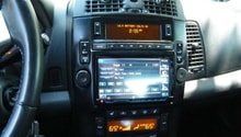
In this article we talk about updating the old electronics in the 4th generation F-body by adding an auxiliary in so you can play music directly from your phone without the need of any kind of adapter.
This article applies to the Camaro and Firebird (1998-2002).
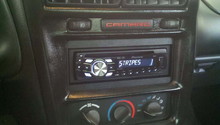
Nothing is worse than having a great car with old technology inside of it. This article explores how to update the factory radio to accept a 3.5mm jack that you can plug into your phone or MP3 player.
Materials Needed
- 7mm, 5mm sockets
- Hand ratchet
- Nylon pry tool
- Wire strippers capable of stripping wire as small as 26 AWG
- Razor knife
- Auxiliary port
- Toggle switch
- T15 Torx screwdriver
- Needle nose pliers (optional)
- Soldering iron (optional)
Step 1 – Remove the radio bezel
1993-1996 Camaro
Remove four screws from the drivers knee bolster. Open the glove box and remove the three screws on the right edge of the radio bezel. Pull the bezel straight back and it will come off.
1998-2002 Camaro
The radio bezel is the piece that houses the center vents, as well as the fog light switch, and ASR switch (if so equipped). It is held in by metal pressure clips. Carefully insert your nylon pry tool between the radio bezel and the dash and gently pry outwards. The clips should release without too much effort.
1993-2002 Firebird
Insert your nylon pry tool between the radio bezel and the dash and gently pry outwards.
Pro Tip
The bezels in these cars is made of ABS plastic. Over time this plastic can become very brittle. Take care when removing to not crack or break them.
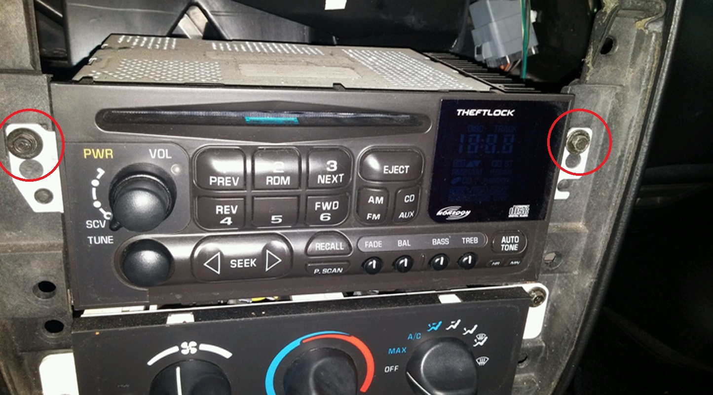
Step 2 – Unbolt the radio and remove
Using a 7mm socket, remove the two bolts (four in the case of the Firebird) and pull the radio out. Disconnect the antenna plug and then the radio harnesses, then remove from the vehicle.
Pro Tip
On some rare occasions, the antenna plug can be in there rather tight. Do not pull by the antenna wire or else you will run the risk of destroying the connector. If you cannot get it out by hand, get a pair of needle nose pliers and gently squeeze the metal portion of the plug and pry it out.
Step 3 – Remove the bottom cover of the radio
Using the T-15 Torx driver, remove the silver screw from the bottom of the radio. Then, with the 5mm socket, remove the two bronze screws from the back. The bottom panel should easily lift off the radio.
Step 4 – Prep the wiring
Notice the white connector with the white and black wires on the main board. This is the connector that leads to the CD player. The wire colors vary by year, but for the most part they will all be white. Locate the wire closest to the back of the radio. This wire carries the positive audio signal for your left speakers. The wire next to it is the negative for both left and right speakers. The third wire on the connector carries the positive signal for the right speakers. The 7th wire on the connector is the power wire for the CD Player.
On your aux cable, locate the left and right wires, as well as the negative (depending upon the cable, this may or may not be shared. If it is separate just twist the wires together). On the switch, strip the ends of both wires and then route them with the auxiliary wiring into the radio.
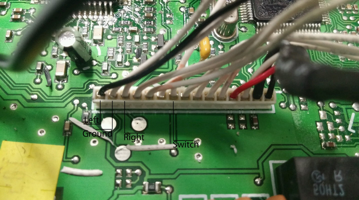
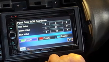
Figure 2. These are the connections you'll need to make. 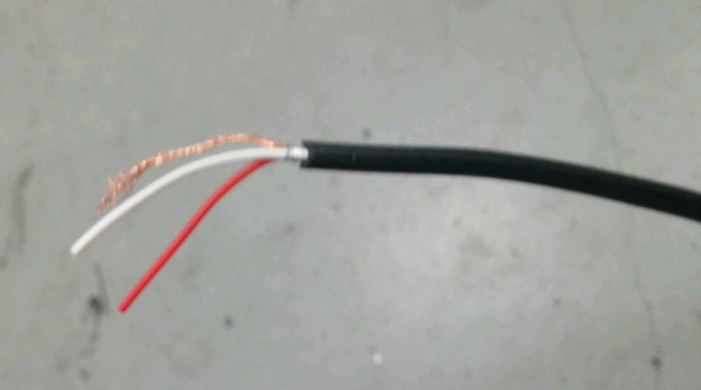
Figure 3. Left is white, Right is red.
Pro Tip
There are multiple holes to route the wires through. One is located just below the radio support, though it is rather small. Another is located on the right hand side, near the disc changer plug.
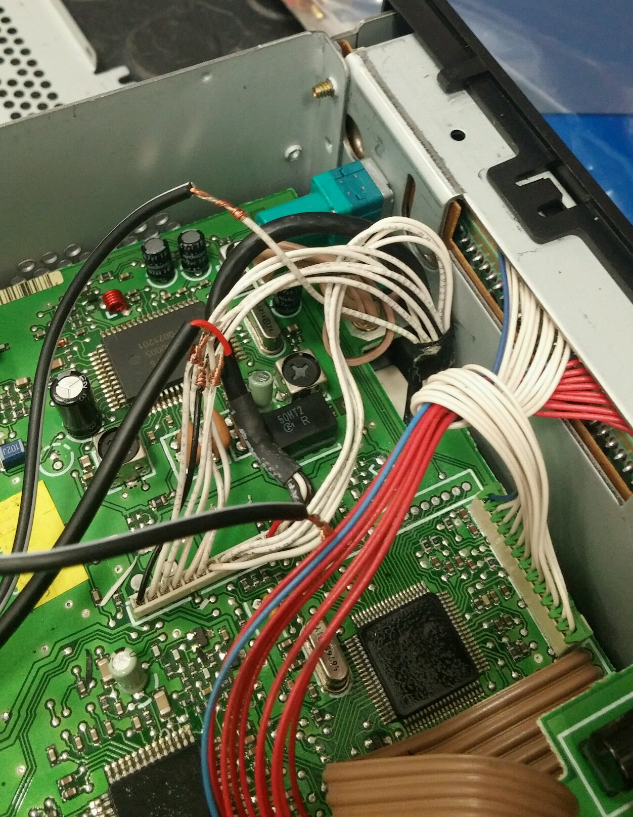
Step 5 – Wire the aux port and switch to the radio
Using your wire strippers and razor knife, carefully strip the insulation off of the wires and wrap the corresponding wire from the aux port around it. On the 7th wire, leaving as much slack as possible on both sides, carefully cut the wire and strip each end. Then, twist the wires coming from the switch onto these ends. Wrap all exposed connections with tape.
Pro Tip
If you have a soldering iron, soldering the connections will guarantee a much stronger bond between the two wires.
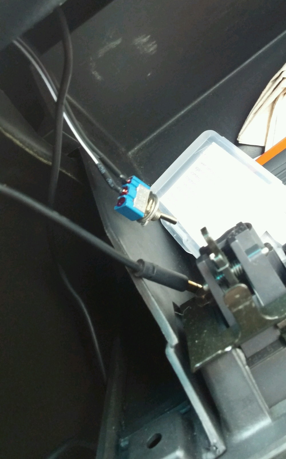
Step 6 – Route the wires inside the vehicle and test the radio
Back inside the car, plug the radio back into the normal connections and route your auxiliary and switch to your preferred location inside the car. The glove box is the most common and most easily reached place. Carefully reinsert the radio and reinstall the mounting screws.
Step 7 – Reassemble the dash
All vehicles: Reassembly is reverse of disassembly, be sure not to forget any screws.
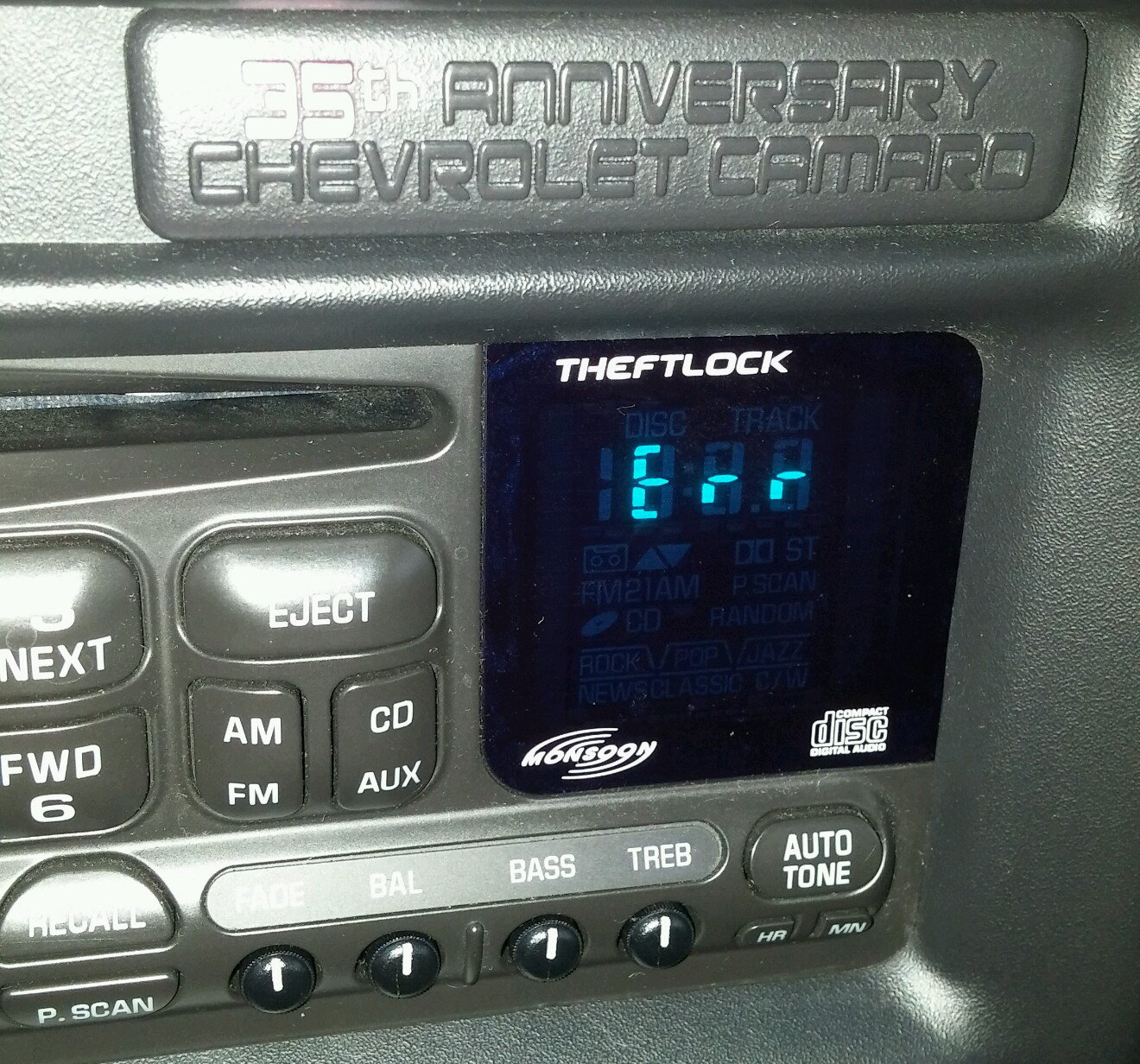
Turn the ignition on and test that the radio still functions (all buttons work, radio, etc.). Insert a CD into the radio, and then flip the switch you installed to the "off" position. The radio will display "Err" and automatically switch to the radio. Plug your phone into the auxiliary, then press the CD button on the radio. It will switch back to the CD, but it should play audio from your phone now.
Related Discussions
- Aux input to factory Delco head, best method - LS1Tech.com
- How you can add add an aux input/mp3 player without an adapter - LS1Tech.com