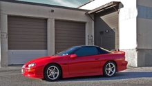
Camaro and Firebird: How to Remove Engine from Bottom
During assembly at the GM production plants, the 4th Gen F-Body received its engine up through the bottom of the car. It only makes sense to remove it the same way.
This article applies to the LS1 Camaro Z28/SS (1998-2002) and Firebird/Trans Am (1998-2002).
The 4th Gen F-Body is built like the other generations of F-Bodies, with a front subframe assembly and K-member. Sitting atop the K-member is the LS1 engine. To get the engine out is a chore no matter how you do it. The way the factory put the engine in is through the bottom, marrying the subframe to the body. There really isn't much holding the the two together, yet the bolts which do hold it in are substantial. This article covers one of the two ways for taking the engine out and that is through the bottom of the car.

Materials Needed
- General tool set to include ratchet, breaker bar, and sockets
- Floor jack and Jack stands
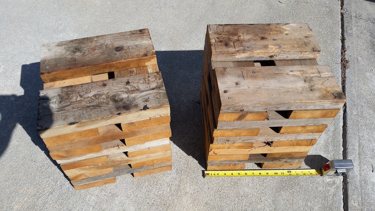
- Wooden jack stand towers
- Cherry picker or vehicle lift
- Fuel line disconnect tool
- Rags
- Long tow or lifting strap
- 10+' piece of rope
This how-to article will cover taking it out using a cherry picker, as most of us do not own vehicle lifts. In order to get the struts/springs to clear, you have to lift the vehicle high enough. With that in mind, you need to create a pair of wooden "towers" to set the jack stands on when supporting the front of the vehicle (seen in Figure 1). The ones enthusiasts created are about 14" square on the base and 15" tall. Use 2x6" boards and screw them together using 3" deck screws. You may need to adjust the base size of the towers to ensure your jack stands sit plainly on them. This article also assumes you'll be leaving the wiring harness attached to the engine as you pull it out.
Step 1 – Drain coolant
Use a clean drain pan. Decide if you are going to reuse the coolant or use new. If going new, dispose of the old properly. While the coolant is draining, remove the hood from its hinges to give you more room to work.
(Related Article: How to Flush Radiator Coolant - LS1Tech.com)
Step 2 – Disconnect or remove wiring/connections
Here is a comprehensive list of wiring and connections which needs to be disconnected or removed:
- Battery's negative, and then positive. It is important that you disconnect in this order.
- Body ground behind battery (10mm stud).
- Two (2) harness connectors inside the cabin, passenger's side, underneath the carpet and behind the plastic kick panel. This wiring goes through to the PCM in the engine bay.
- Remove the shift knob and shift boot (if a manual).
- Intake Air Temperature (IAT) sensor, Mass Airflow (MAF), Throttle Position Sensor (TPS). When you are done here, remove the air lid, MAF, and bellows.
- Disconnect small coolant hose attached to the coolant pipe under the intake manifold.
- Remove throttle cable from throttle body. Disconnect throttle cables from intake and where attached to heater hose lines.
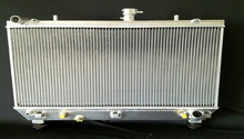
- Detach upper and lower radiator hoses from engine. Fold them over on themselves and press them in somewhere so they are out of the way. Also, detach heater hoses from water pump.
- Disconnect fuel line using the fuel line disconnect tool (3/8"). Also, disconnect fuel evaporator line from the small black canister lying on the intake manifold.
- Remove the steering shaft.
- Remove the brake booster hose at the booster.
- Detach the master cylinder from the brake booster. Once it's off, push it up above the windshield cowl so you will have room to remove the strut tower bolts.
- Remove bolts from the struts at the towers. Loosen the nuts, but leave them in place for now. On the driver's side, there are two T50 Torx bolts and two 15mm nuts. On the passenger's side, there are two 15mm nuts and two 13mm bolts. When done, move the brake master cylinder back into position to relieve strain on the brake lines.
- Disconnect the front brake lines from the Electronic Brake Control Module (Figure 2). Be prepared to wrap the lines in rags so as to not drip brake fluid onto your paint. Follow the lines down the side of the frame area. There is an aluminum heat shield there held on by four 10mm bolts. Two can be removed from the top, the other two you can get from the bottom. When you pull it out, you will see a black/gray bracket that holds the brake lines. Pop the front brake lines from the bracket. Also, remove the nearby black cable from the bracket by undoing the clip.

- Remove the positive cable from the post on the fuse box. It's a 15mm bolt: pull ring terminal off.
- Below the fuse box on the driver’s side, there is a ground strap held on with a 10mm bolt that needs to be removed (Figure 3).

- Remove the fan belt.
- Disconnect the A/C compressor from the engine. Start by unplugging the A/C clutch wiring. Then remove the top two 15mm bolts on the A/C bracket. The bottom two 15mm can be removed from under the vehicle, then swing the compressor and hoses connected to it towards the front of the car.
- Remove the PCM by loosening the captured 7mm bolts in the red and blue connectors. Then remove the black bracket, which is held on with two 10mm bolts. Now you can pull the body harness through the firewall to include the grommet. Remove any clips on the firewall.
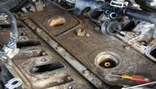
- Disconnect the vacuum line from the heater box (Figure 4).

- Unplug the pressure switch connector from the evaporator tube (A/C line on passenger's side).
- Disconnect the connectors that hold the wiring along the passenger's side fender.
- Disconnect the speed sensor connection at the wheels on both, then disconnect the wire from the K-member.
- Remove the thin rubber dam on the driver's side of the vehicle (Figure 5).

- Remove the other two 10mm bolts from the brake line heat shield if not already done.
- There are two harnesses running on the engine side of the electric fans. One actually has connectors going into the motors; you do not need to disconnect that one. The other is fatter and is attached to the shroud with clips. Pull this harness loose from the clips.
- Following the same harness, track it back and unplug the necessary connector from the AIR pump.
- If you have an automatic transmission, detach the transmission fluid lines from the radiator. Wrap the lines in rags so as to prevent a lot of leakage.
- Also, for an auto, remove the shift selector cable by prying it off with a screwdriver. Then remove the two 13mm bolts that secure it to the transmission pan so that it dangles.
- For a manual car, detach the clutch hydraulic line, which runs into the side of the transmission. There is a white ring that needs to be depressed with two flat tip screwdrivers, then it will pop out.
- Also, for a manual, take the shifter out by removing the four bolts. While not completely necessary, it makes it much easier to get the engine/transmission in and out.
- Detach the sway bar mounts from the front end of the car. The two mounts are attached with 13mm bolts. Let the sway bar hang.
- Disconnect the O2 sensor connectors and wrap the wires up so they won't get caught on anything.
- Disconnect your Y-Pipe. Headers or manifolds can remain on the engine.
- Remove the driveshaft.
- Disconnect the torque arm from the transmission.
- Do a once over to ensure no wires/connection have been missed. Remove as necessary.
Pro Tip
If you have an old driveshaft you no longer need, pull the slip yoke out of it and use it as a transmission plug. This keeps transmission fluid from going everywhere when pulling the engine and/or transmission.
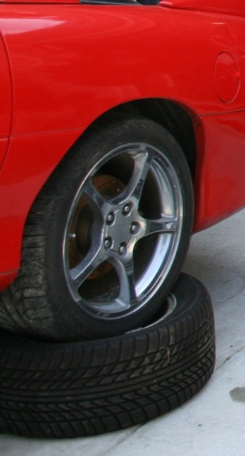
Step 3 – Put rear tires up on spares
Jack the back end of the vehicle up so the wheels are up off of the ground. Put spare tires/rims under the wheels located on the axles. This gives you extra clearance up front when pulling the engine/transmission out from under the car (Figure 6). Set your wooden towers and jack stands next to the vehicle.
Step 4 – Disconnect transmission brace
Place a floor jack under the transmission brace and jack it up to take the weight from it. Remove the four 15mm bolts, which attach the transmission brace to the body. You can leave the transmission brace hanging from the transmission mount. Lower the jack just enough to ensure the transmission brace has come free from the body.
Step 5 – Remove subframe bolts
Attach your cherry picker to the engine so you can lift it and the front end of the vehicle just enough to take the weight off of it. Remove the six 18mm bolts that hold the subframe to the car (Figures 7 and 8). When the bolts are out, slowly lower the cherry picker arm.

Figure 7. Subframe bolts on driver's side. 
Figure 8. Subframe bolts on passenger side.
Step 6 – Lift the front of the car
Re-position the cherry picker back a little bit. Attache the tow strap through the braces in the front of the car left and right (just behind the headlights). There are holes there you can pull your strap through. Secure this through the hook on the cherry picker. Make it so there isn't a lot of slack in the strap, but enough so there isn't a bunch of stress on the front braces. Once you are sure the strap is secure and you are ready, begin lifting the front of the vehicle. You should see the struts start to pull away from the towers. Remove the four 15mm nuts holding the struts in place. Continue jacking the front of the vehicle, looking all the time for anything which may be hanging up (brake lines are notorious since they are hook shaped). Take your time and continue to lift. A spare set of eyes during this phase is a great help. When the body is clear of the engine, continue to lift the front of the car so you can put the wooden towers and jack stands under it. It should look something like Figure 9 and 10 when you're done. When the jack stands are in position, lower the front of the vehicle down and disconnect the cherry picker. Roll the cherry picker back some, as you'll use it to pick up the engine in the next step.
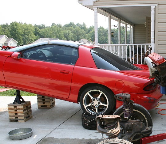
Figure 9. Car on blocks side view. 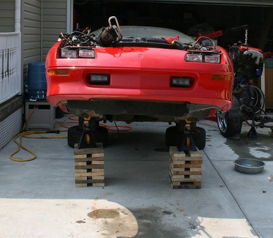
Figure 10. Car on blocks front view.
Step 7 – Roll engine out
Using a piece of rope, tie the two struts together over the top of the engine. Arrange all the wiring and anything dangling on top of the engine as well. When ready, carefully roll the engine out from under the vehicle. The rolling floor jack should still be under the transmission and the tires should still be in place. Rolling the tires should bring the engine out from under the vehicle. After the engine is completely out, use the cherry picker to lift the assembly for easier maneuvering.
Related Discussions
- How to Remove Engine From the Bottom LS1 F-Body - LS1Tech.com
- How to Remove Engine From the Bottom - LS1Tech.com
- How to Drop the Engine from Bottom with K-member - LS1Tech.com
- Engine Removal Out the Bottom ... How to Support the Engine and Remove Bolts at the Same Time - LS1Tech.com