Camaro and Firebird: Steering Column Disassembly
The steering column doesn't just hold the steering wheel, it contains switches for many vehicle accessories. Lots of parts make up the steering column, but careful disassembly along with our pictures and guide will help you fix it.
This article applies to the Camaro and Firebird (1993-2002), as well as C5 Corvette (1997-2004).
The steering column holds the large shaft between the steering wheel and steering rack, but that's not all. It is also a convenient place to put the controls for all sorts of other driver functions, like the high beam dimmer and the blinkers. If you need to disassemble the entire column, to fix one of these electric issues, or to replace the bearings and bushings that hold the actual steering shaft inside, organizing the parts into separate labeled zip lock bags will make re-installation much easier. Along with the brakes, the steering column is one of the most important safety systems in your car, so great care should be taken in putting it all back together properly, so as to keep the steering wheel turning free and accurately.
Materials Needed
- Steering wheel puller
- Steering pivot pin remover
- Lock ring remover
- Ratchet
- 8mm, 10mm, 11mm, 13mm, and 21mm sockets
- Phillips and flat head screwdrivers
- Various sized torx and Allen drivers
- Hook/pick tool
- External snap ring pliers
Step 1 – Disconnect battery and airbag
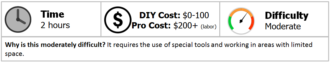
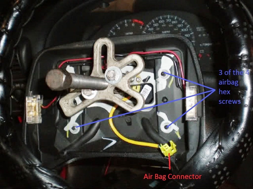
Disconnect the negative (black) battery terminal under the hood. Wait five minutes, then unplug the yellow electrical connector underneath the steering column which powers the airbag.
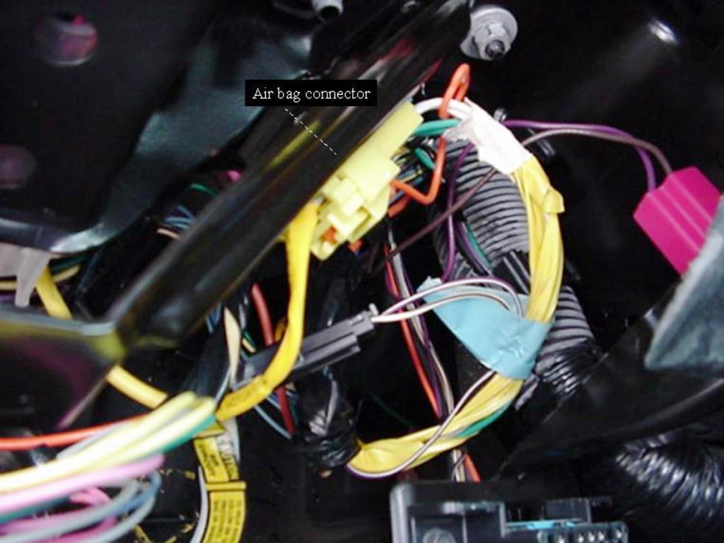
Step 2 – Remove the plastic steering column covers
Separate the top and bottom sections by removing the 8mm bolts and/or Phillips head screws.
Position your wheels and tires straight ahead, then lock the steering column by removing the key from the ignition.
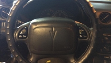
Step 3 – Remove the airbag and steering wheel
Remove the four screws from behind the steering wheel. Carefully lay the airbag face up away from the work area.
Remove the central 21mm nut before installing your steering wheel puller. Determine which bolts fit the wheel and puller, then remove the wheel. It takes a considerable amount of force, so you may even need an impact gun to break it free.
Remove the retaining snap ring from the SIR coil assembly and remove the coil.
Step 4 – Remove shaft lock shield assembly and turn signal cancelling cam
Using a lock ring removal tool, push down the lock ring until the spring bearing retainer becomes accessible. Use a small flat head screwdriver, pick, or snap ring pliers to pry the retainer from the groove.
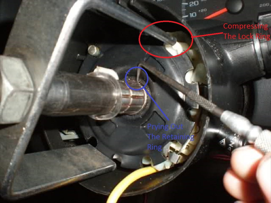
Figure 4. Compressing the lock shield to remove the spring bearing retainer. 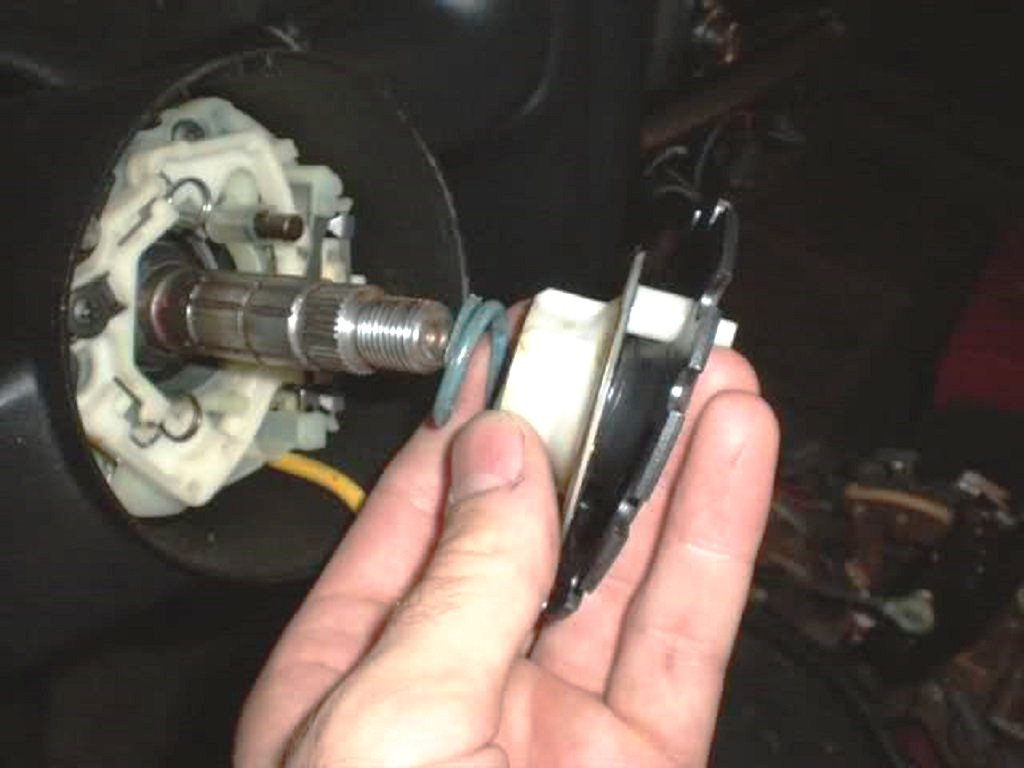
Figure 5. Lock plate shield and spring removal.
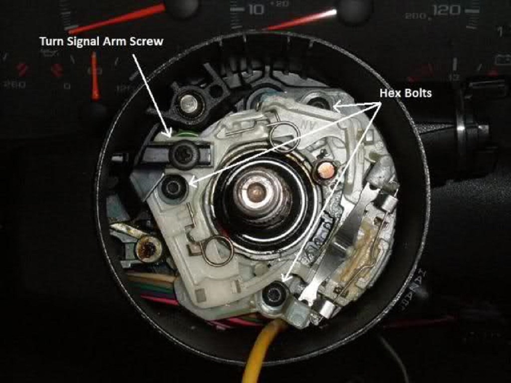
Step 5 – Remove the turn signal arm
Remove the turn signal arm screw and the three Allen bolts for the turn signal arm. Note the notch in the arm and how it fits into the blinker switch.
Step 6 – Disconnect turn signal assembly and remove hazard switch
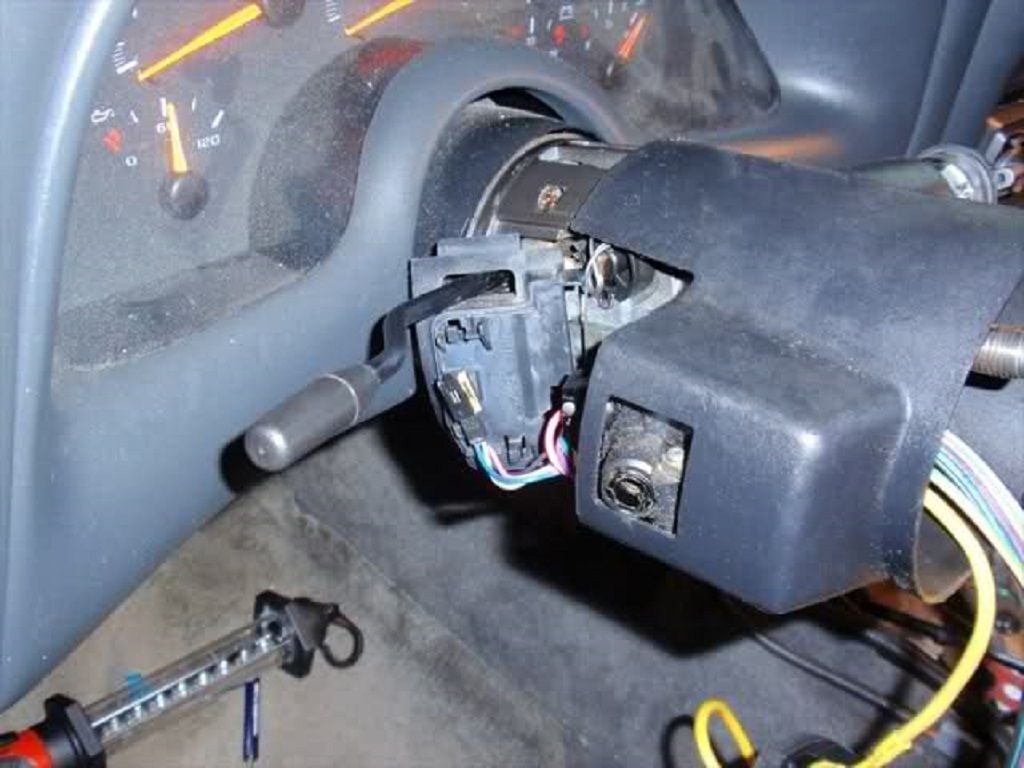
Move to under the steering column. Disconnect the turn signal switch assembly. Remove the hazard switch, but be careful of the spring inside that can be easily lost.
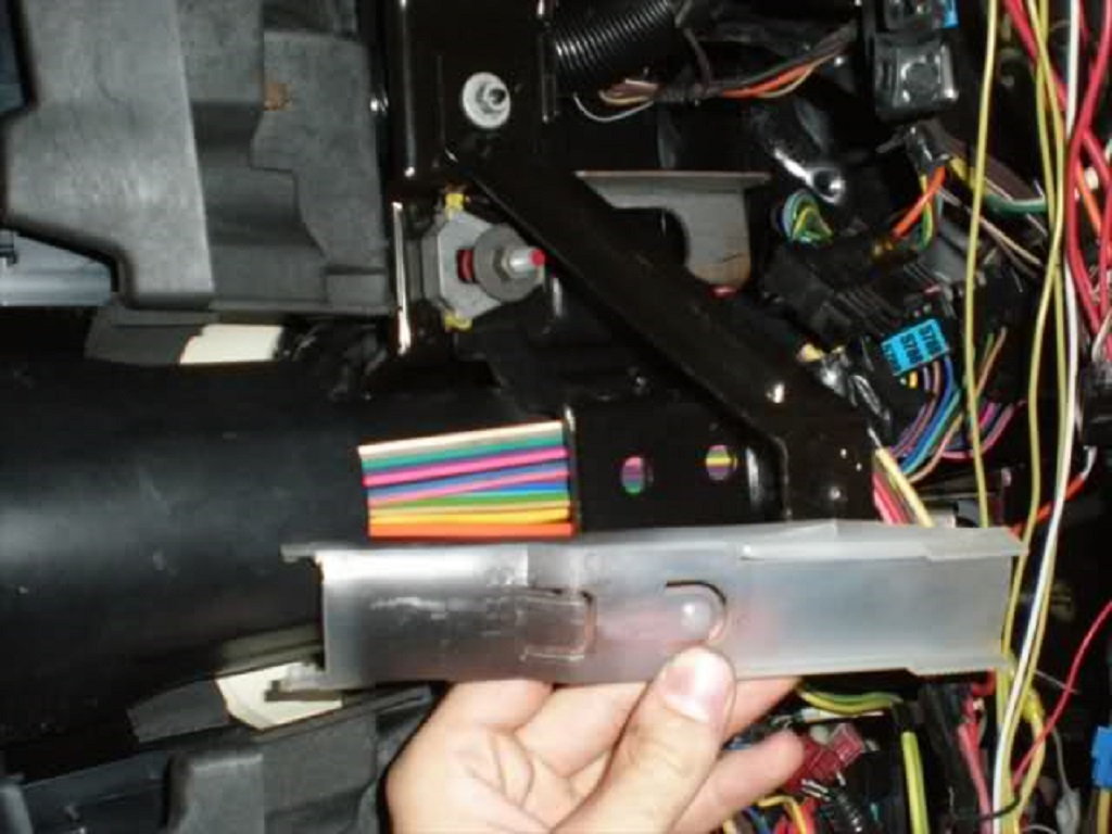
Remove the plastic shielding under the steering column. Slide it out towards the back of the column.
Step 7 – Remove tilt pivot, pulse assembly, and lock cylinder
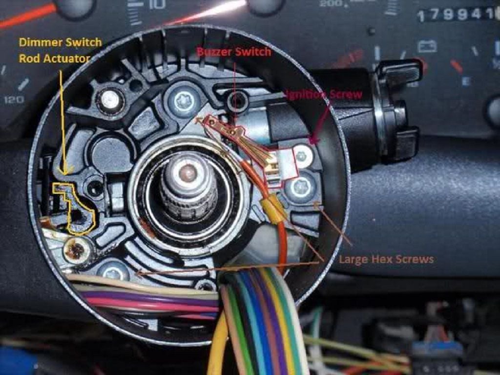
Remove the three large Torx screws holding the pivot and pulse assembly. Remove the ignition switch Allen screw. During removal, the white buzzer switch will push out. Remove the buzzer switch completely and pull the hex screw from the steering column.
Step 8 – Remove tilt lever, lock housing cover, and sleeve assembly
Unscrew the tilt lever counterclockwise. Use vice grips or pliers for added grip if need be, but place a rag between the pliers and tilt lever to reduce damage. Once the lever is removed, the dimmer switch rod actuator (refer to Figure 7) may fall from behind the column housing cover end base plate, but be careful not to lose it. Remove the lock housing cover and sleeve assembly with the disconnected wires. Slide the wiring past the steering column housing.
Step 9 – Remove the steering column housing
Begin by removing the pivot pins using a steering pivot pin remover. Screw the remover into the center of the pins to pop them out. Now remove the "upper bearing inner race seat" by pulling it from the steering shaft with a hook or similar tool.
To remove the steering column housing, re-attach your tilt lever and pull it back to fully disengage the steering wheel lock shoes. Tilt up on the housing and wiggle it free.
Begin pulling the steering column housing off. Watch for the "wheel tilt spring" and the "switch actuator rack."
Replace your steering column housing support assembly if needed by removing the four screws holding it in place.
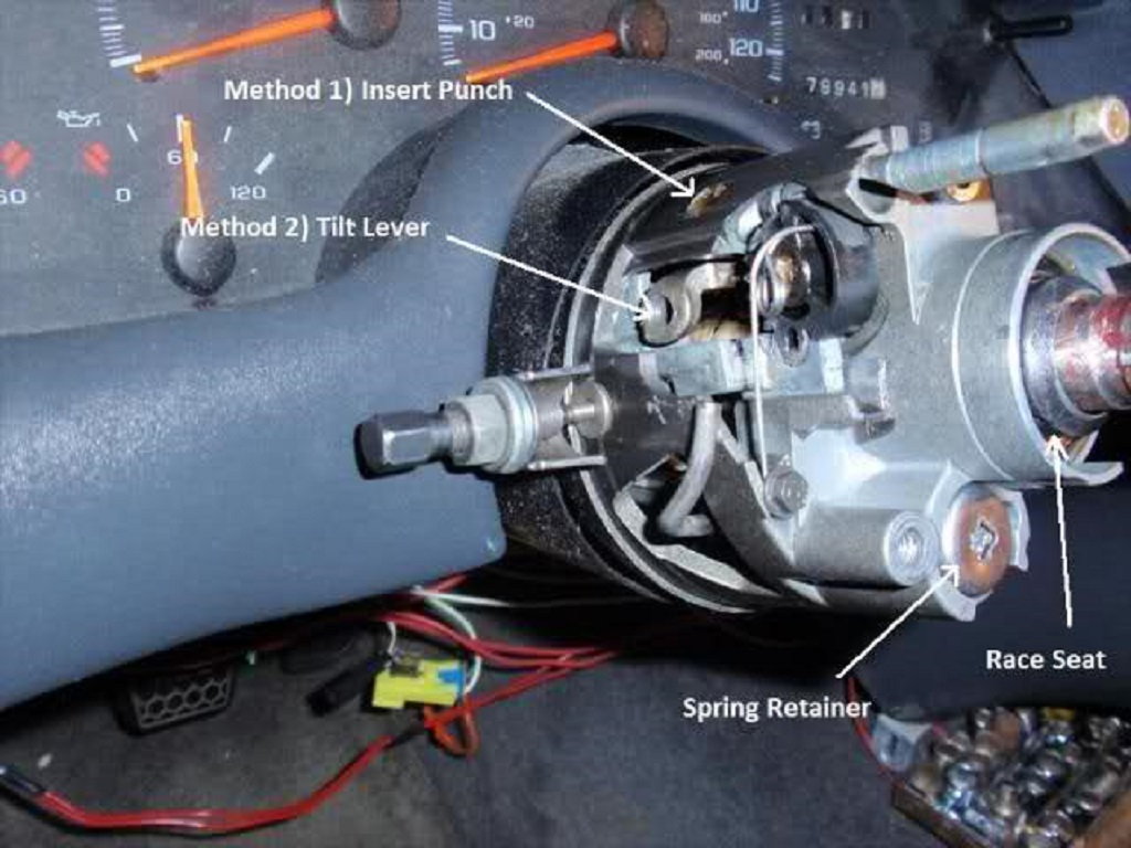
Figure 10. Removing the pivot pins. 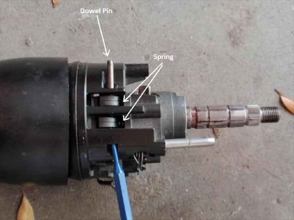
Figure 11. The steering shaft dowel pin.
Step 10 – Remove steering shaft from the steering column
Remove the 11mm bolt connecting the steering shaft to the intermediate steering shaft. Remove the "lower bearing adapter," which is located at the bottom of the steering column in the engine bay. Remove the clip, bearing cover, and the beige plastic cover using a flat head screwdriver or pry bar.
To remove the steering column from the car, remove the three 10mm bolts at the base of the steering column that hold it to the floor. Also, remove the two 13mm bolts further up. Removing the metal cross brace (two 10mm bolts) will provide easier access to the 13mm bolts. With the steering column loose, you can easily undo the electrical connectors for the dimmer and ignition switches, but be careful not to let the weight of the column hang on the wiring or you may damage it.
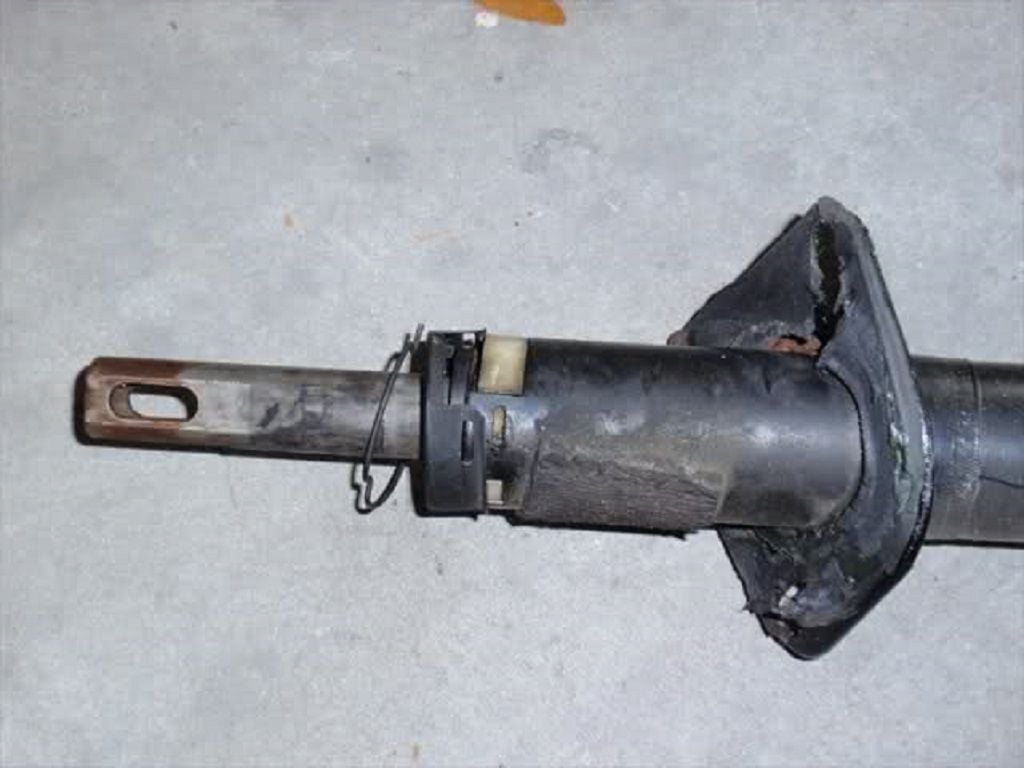
Figure 12. The lower steering column shaft. 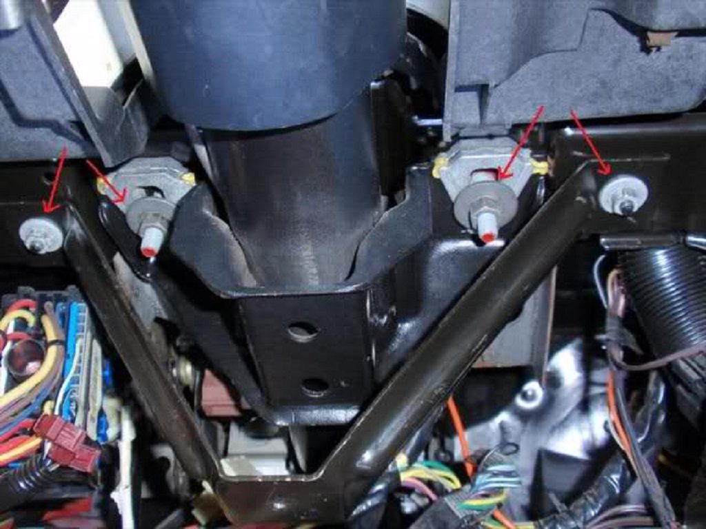
Figure 13. The steering column mounting bolts.
Step 11 – Re-assemble
Install and secure the steering column into the car. If you removed the ignition and/or dimmer switches, properly position the ignition switch actuator rack. Attach the dimmer switch as well.
Apply grease (lithium or wheel bearing) to any and all load bearing joints. Put the steering shaft back into the steering column. Re-install the lower bearing adapter and the retainer. Align the ignition switch actuator rack with the ignition switch actuator assembly while re-installing the steering column housing. The end of the actuator rack should fit in a notch on the actuator assembly.
Install the pivot pins by aligning the steering column housing and locking the steering wheel lock shoes. Tap the pivot pins into the installed position with a hammer. Re-install the tilt spring and retainer. Turn the retainer clockwise while applying downward pressure to connect it to the spring.
Slide the inner race seat back onto the steering shaft. Route all of the electrical connectors back through the opening and re-install the plastic wire shield.
Slide the steering column housing back on and align the dimmer switch rod actuator with the dimmer switch rod. Secure the steering column housing with three Torx screws. Install the end base plate cover. It keeps the dimmer switch rod aligned with the actuator. Moving the rod without the base plate installed may damage the rod.
Re-install the turn signal switch assembly with three Allen screws and secure the signal switch arm with the Phillips head screw. Re-install the upper bearing spring, and turn signal canceling cam.
Install the lock plate and wave washer by aligning them with the notch at the top of the upper shaft. Install the retaining ring using the lock pin removal tool. Re-install the inflatable restraint coil assembly and retaining ring. Align the notch in the steering wheel with the notch on the steering shaft, then tighten the steering wheel with the 21mm nut. Re-install the airbag with the four screws.
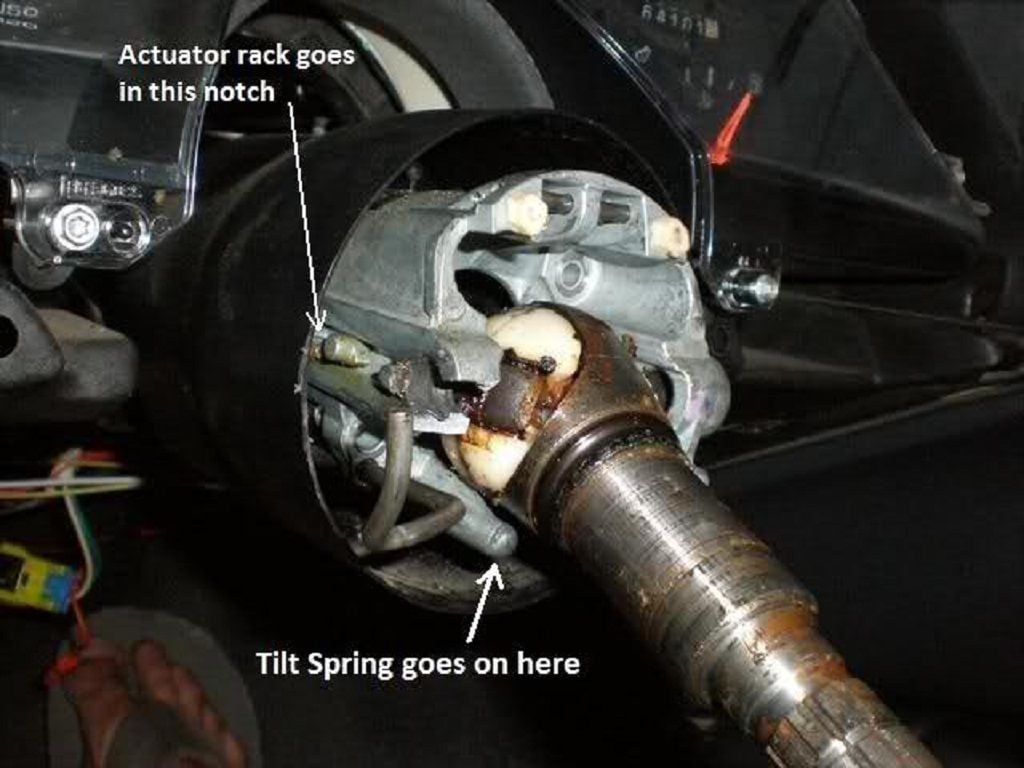
Figure 14. Aligning the actuator rod and installing the tilt spring. 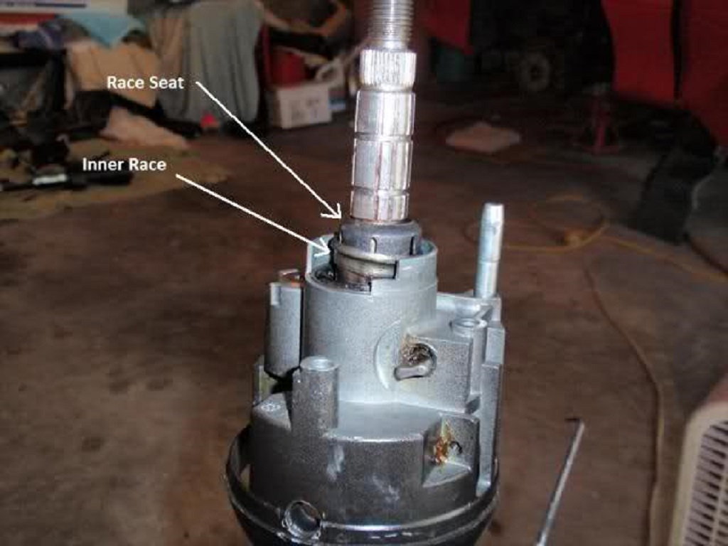
Figure 15. Installing the inner race onto the race seat. 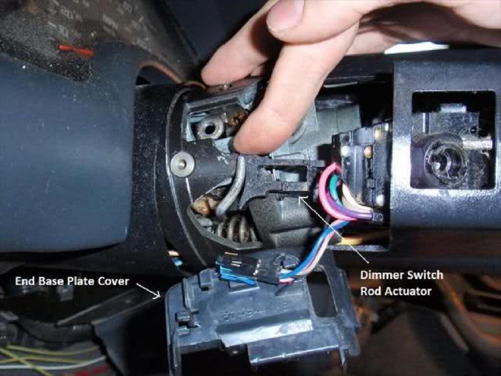
Figure 16. Locating and installing the base plate cover. 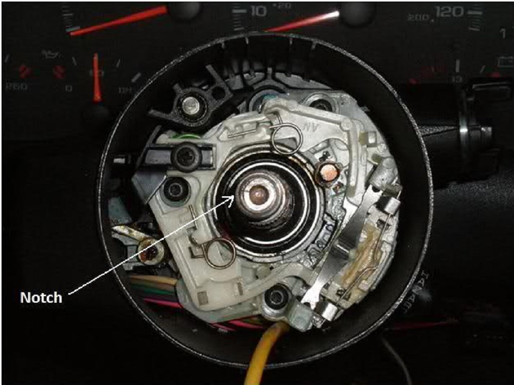
Figure 17. The notch at the top of the steering shaft.
Related Discussions
- Steering Column Removal and Disassemble with pics - LS1Tech.com
- How To Steering Coulumn Repair - LS1Tech.com
- Intermediate Steering Shaft Replacement - LS1Tech.com