

Rebuilding a 4L80 tips? tricks?
 04-10-2018, 04:15 PM
#61


Just got off the phone with Green Sales. They don't have the bearing in stock anymore and will likely not be stocking it again.
The next question is, what about using a different torrington bearing. I have several from a busted 4L60.... Looks like one could be made to work but it's going to be more involved machining wise.
Maroon, don't know if this helps but it's a good read on that topic.
http://www.gearsmagazine.com/magazin...4l80-rebuilds/
 04-25-2018, 02:56 PM
#62
Still slowly working on this 4L80 project. I made it up to the 4th clutch last night. Even managed to bypass the purchase of the $400 lip seal tools to do the 4th clutch!!!
Going to keep pushing on this 4L80 and will post pics etc soon. I've got a lot of em lol.
I gave up on finding the correct Torrington bearing to rollerize the forward hub. Don't think it will matter behind a 400-500 HP application anyways.
Going to keep pushing on this 4L80 and will post pics etc soon. I've got a lot of em lol.
I gave up on finding the correct Torrington bearing to rollerize the forward hub. Don't think it will matter behind a 400-500 HP application anyways.
05-09-2018, 12:01 AM
#64
You changed your mind because of my thread  ??
??
I've been busy so I haven't been able to breeze through this as fast as I'd like. And, I have purchased ZERO special tools for this job. Instead, I've been fabricating every special tool needed to do a 4L80 as I go which makes it take a little longer still. Overall it's been pretty easy, lots of big beefy parts that are easy to manipulate, not a whole lot of **** you off little parts that are hard to deal with...
All that I lack on finishing this project is the valve body and it will be a done deal. I started on it a couple nights ago and I'm roughly 1/3 of the way done with that so the finish line is in sight!!!
I will post back with the rest of the pictures and descriptions once I'm finished, hopefully it will be a resource to help anyone else who wants to DIY this job.
??I've been busy so I haven't been able to breeze through this as fast as I'd like. And, I have purchased ZERO special tools for this job. Instead, I've been fabricating every special tool needed to do a 4L80 as I go which makes it take a little longer still. Overall it's been pretty easy, lots of big beefy parts that are easy to manipulate, not a whole lot of **** you off little parts that are hard to deal with...
All that I lack on finishing this project is the valve body and it will be a done deal. I started on it a couple nights ago and I'm roughly 1/3 of the way done with that so the finish line is in sight!!!
I will post back with the rest of the pictures and descriptions once I'm finished, hopefully it will be a resource to help anyone else who wants to DIY this job.
 07-02-2018, 12:48 PM
#66

Next we will be working on the intermediate clutch apply piston which is seen here in the center cupport. There is a big snap ring that is removed then you can pull out the piston and the spring retainer which sits on top of the piston.
Here is a pic showing the lip seals on the intermediate piston. You want the lip seals to face DOWN into the bore of the center support.

New lip seals on intermediate piston and lubed with ATF ready to go into the center support bore. Use a gentle twisting motion with even pressure to install most lip seals. You DO NOT want to roll or cute the seals. They are pretty tough from my experience and with a little lube you should be fine but just pay attention to what you're doing.

intermediate piston going in.

Closeup of the snap ring that retains the spring retainer AND intermediate apply piston in the center support.

Pay attention to the orientation of the lube holes in the center support bushing. Make note of that way it was before removing the old bushing and replicate this on the install of the new one.
I used vise grips to clamp down the spring retainer to get the intermediate piston snap ring installed. You can do this by hand as the springs are fairly weak but if you use vise grips be careful not to bend the spring retainer as it is fairly flimsy steel.

Starting to get some things together on the bench.

Here are the shims and the Torrington bearing to rollerize the output.

Shown are the shims in the bag, and the new Torrington bearing and rear case bushing. Also seen on the left are the 3 tang washer from the rear of the case as well as the thrust washer. These are replaced by the bearing and shims in the rollerizing process.

Here is the new rear case bushing and the Torrington bearing for rollerizing the output.

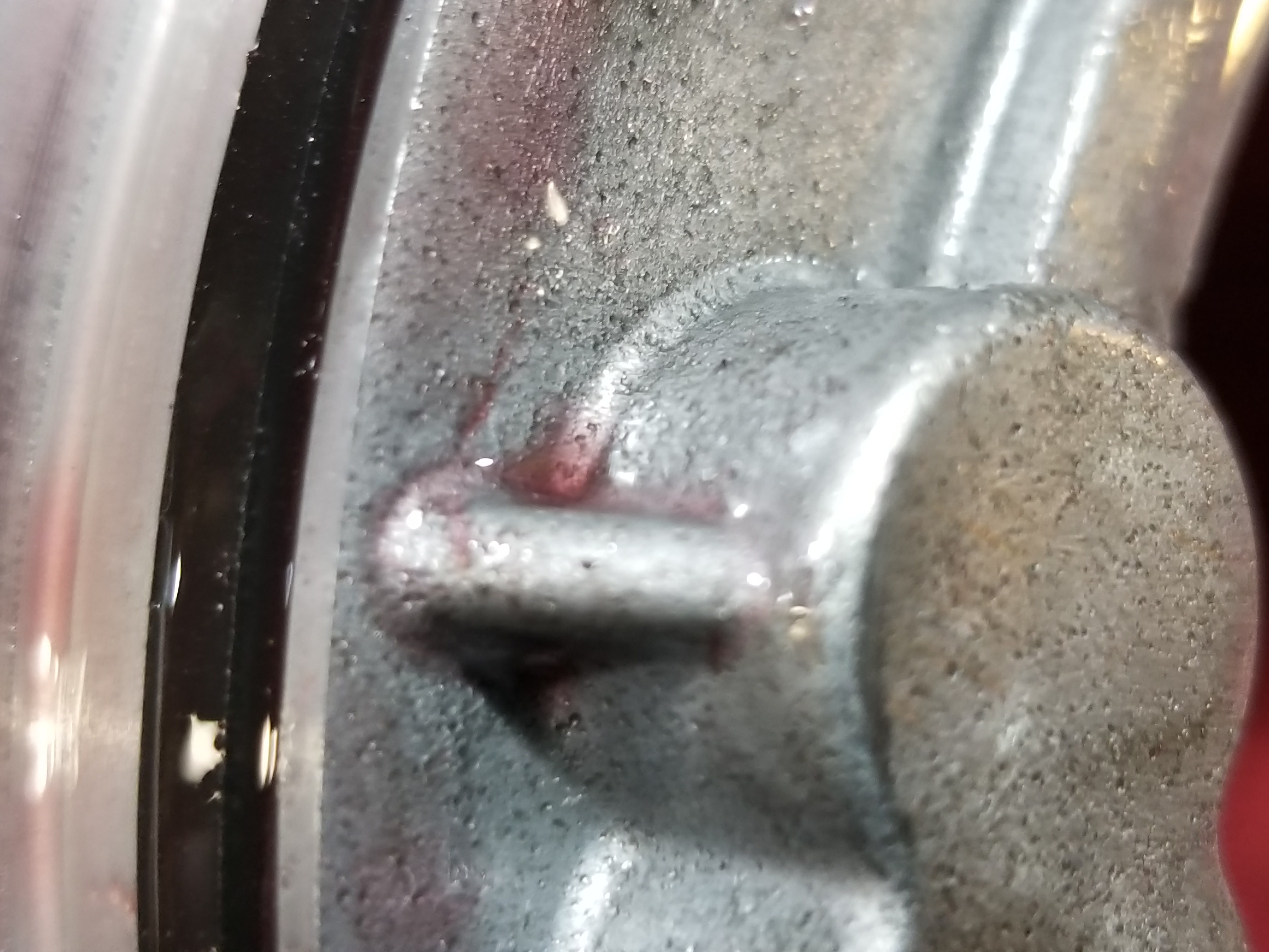
Shown is the factory rear case bushing which will be replaced with the one shown above. We will install this bushing so that it portrudes into the inside of the case so as to provide a register for the shims and Torrington bearing

Another shot of the OEM rear case bushing.

This is something I had laying around that I repurposed into a driver for various seals and bushings. In this pic I'm installing the new rear case bushing. Remember, we want it to portrude into the case to provide a register for the shims and bearing going in here. You can knock the bushing back and forth a bit till you get it correct.

Here I am measuring for the correct amount of "stick out" of the new rear case bushing.

Shown here is the bushing. You can see that it portrudes into the case a ways.

Here is the new Torrington bearing to rollerize the output. Black side faces DOWN or AGAINST the aluminum of the case.

This silver side faces UP. It should face you once you lay it down into the case and are looking down into the case.

It goes in just like this.

Here it is installed.

Soak all frictions in ATF then let them dry somewhere for a bit.

This includes the bands.
With the center support upside down, lay the thrust washer into place and retain with petroleum jelly

Clamp some visegrips on the shaft and get ready to lower the rear geartrain into the case to measure rear unit endplay. You can leave the reaction carrier off for this.
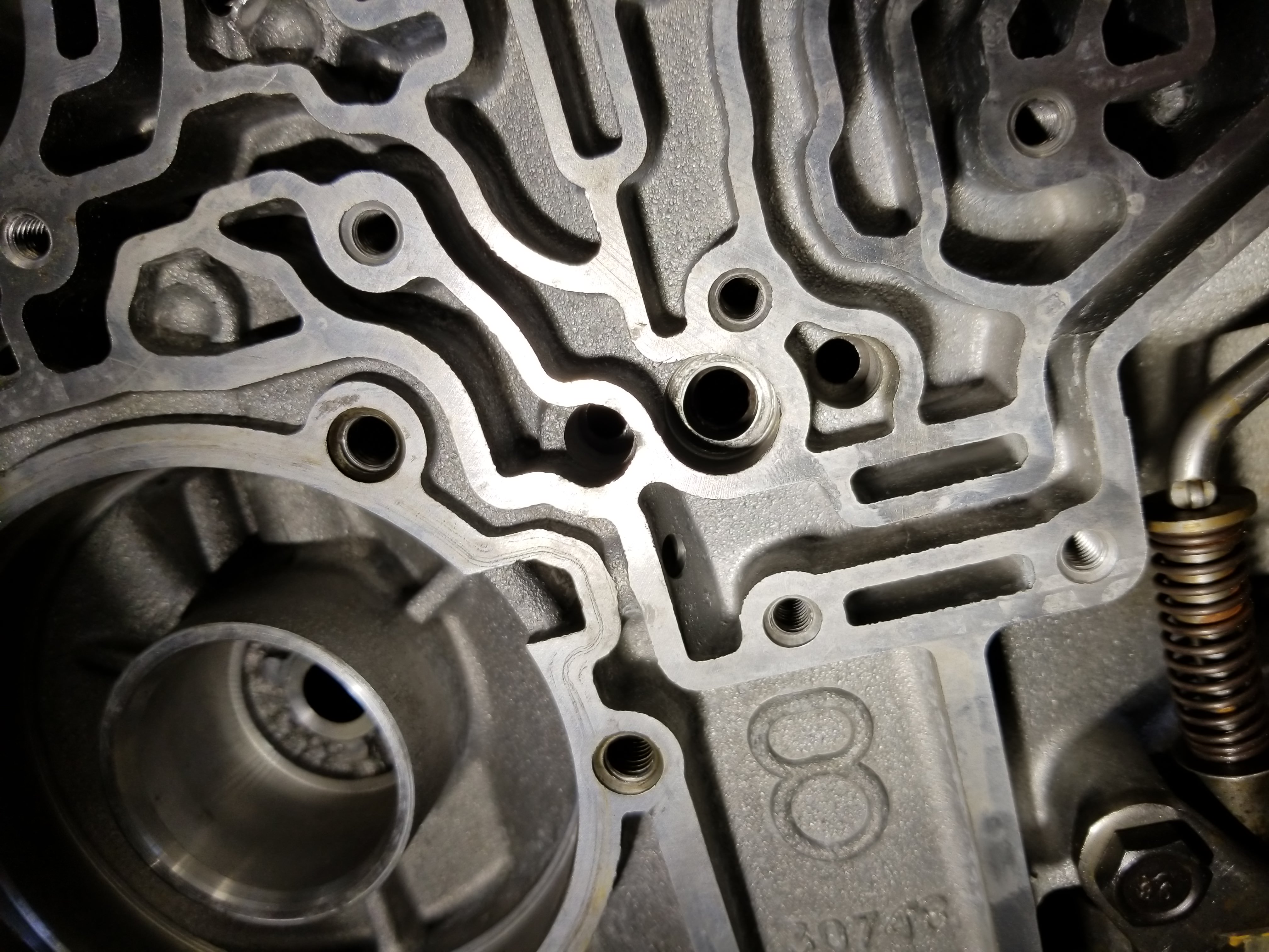
You should see the center support bolt hole line up with the corresponding hole in the case once the rear geartrain is in all the way. It is the bolt hole directly above the number 8 cast into the case. Not the threaded hole but the one right above that.

The rear geartrain is in place minus the reaction carrier which we have left off to do some measuring.

Install the center support snapring with the opening facing the 9 o'clock position.
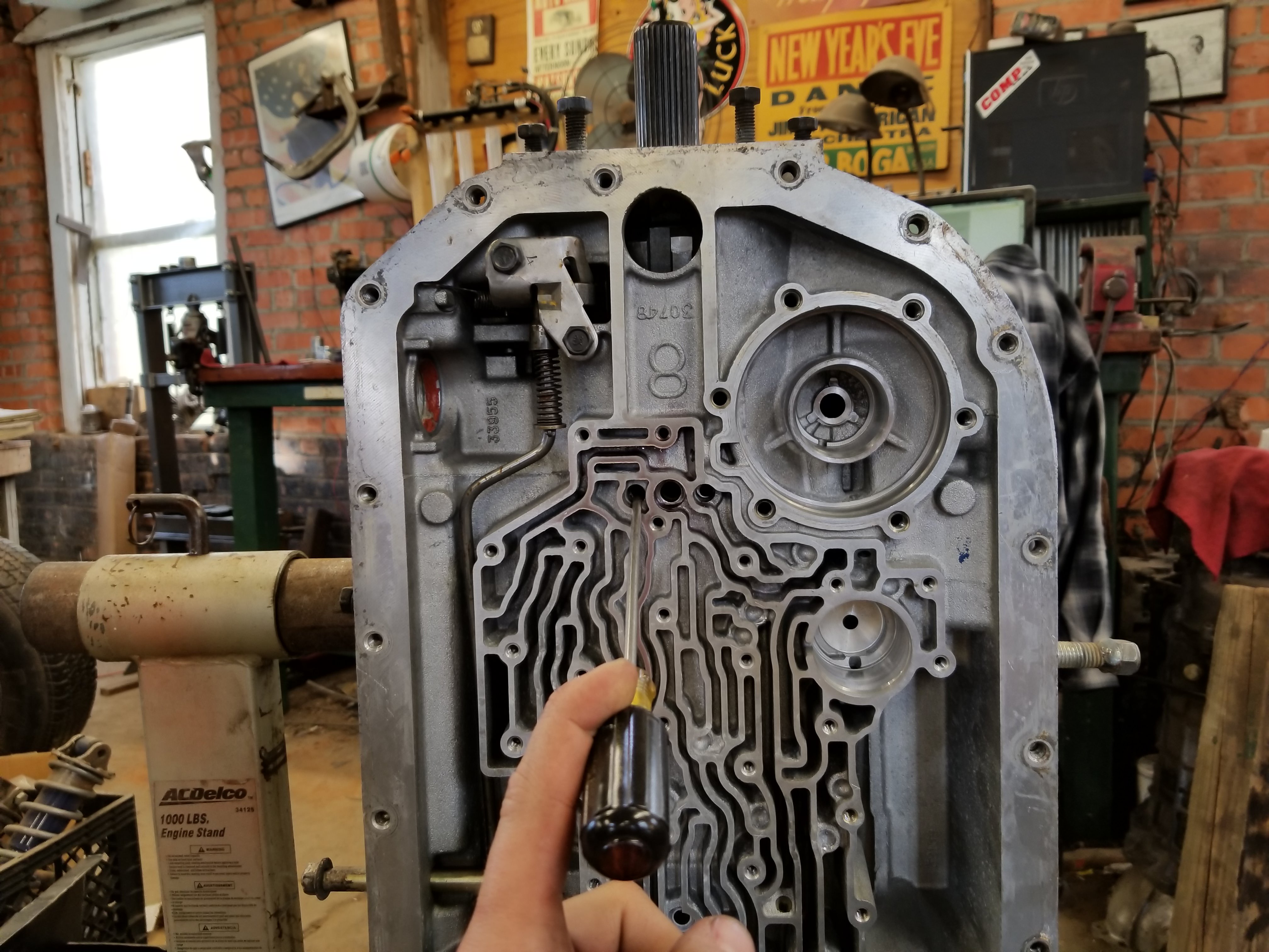
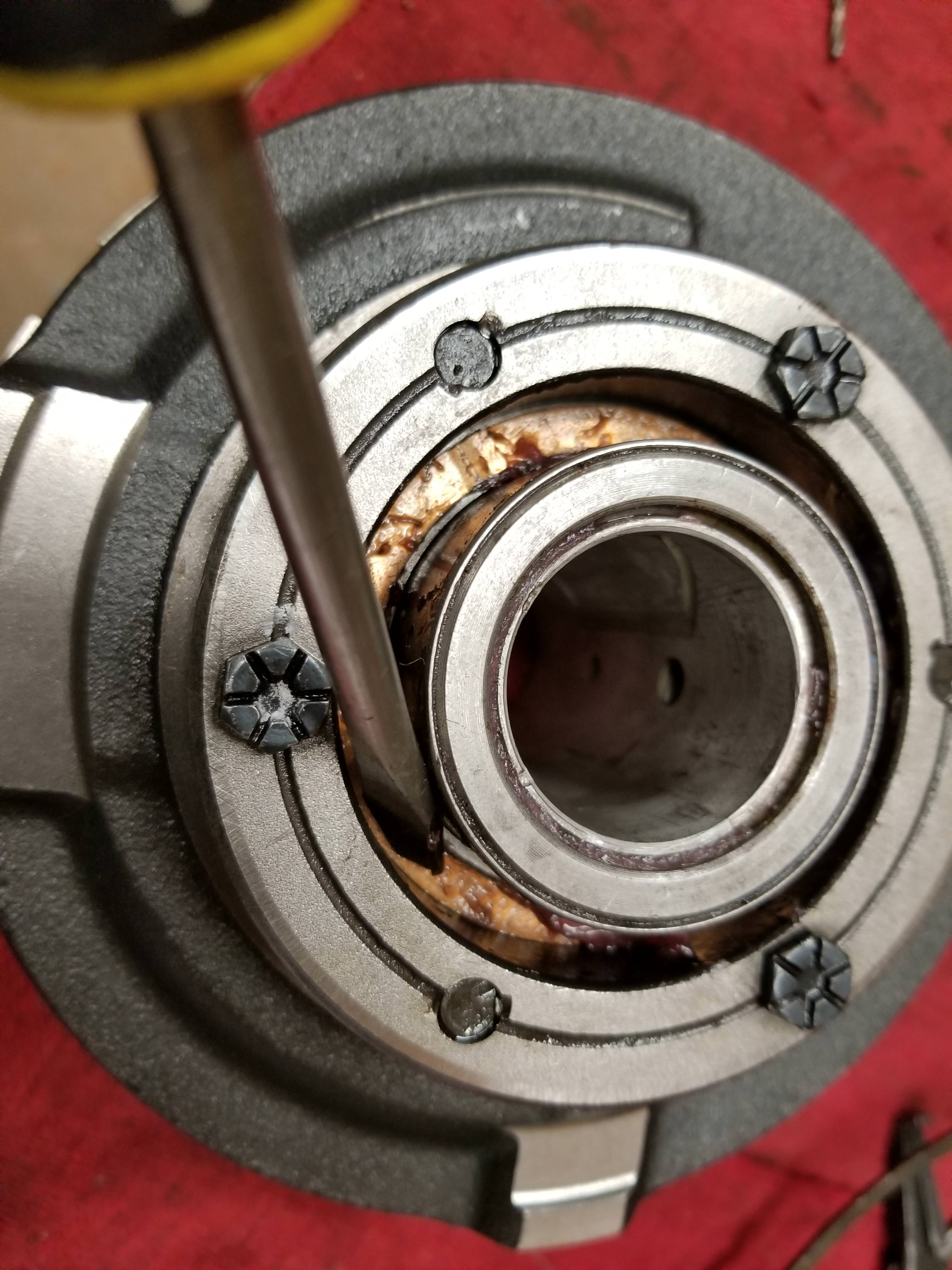
Using a screwdriver you can pry the rear geartrain up and down to measure the rear unit endplay. Select a combination of shims that came with the rollerizing kit to obtain the correct endplay.

Here is one way to mount the dial indicator to measure endplay

Try to get the dial indicator even and square when placing the tip on the output shaft.
Once you get your unit rear endplay established remove the rear geartrain and set it aside.

Now install the rear seal

Followed by the rear snapring
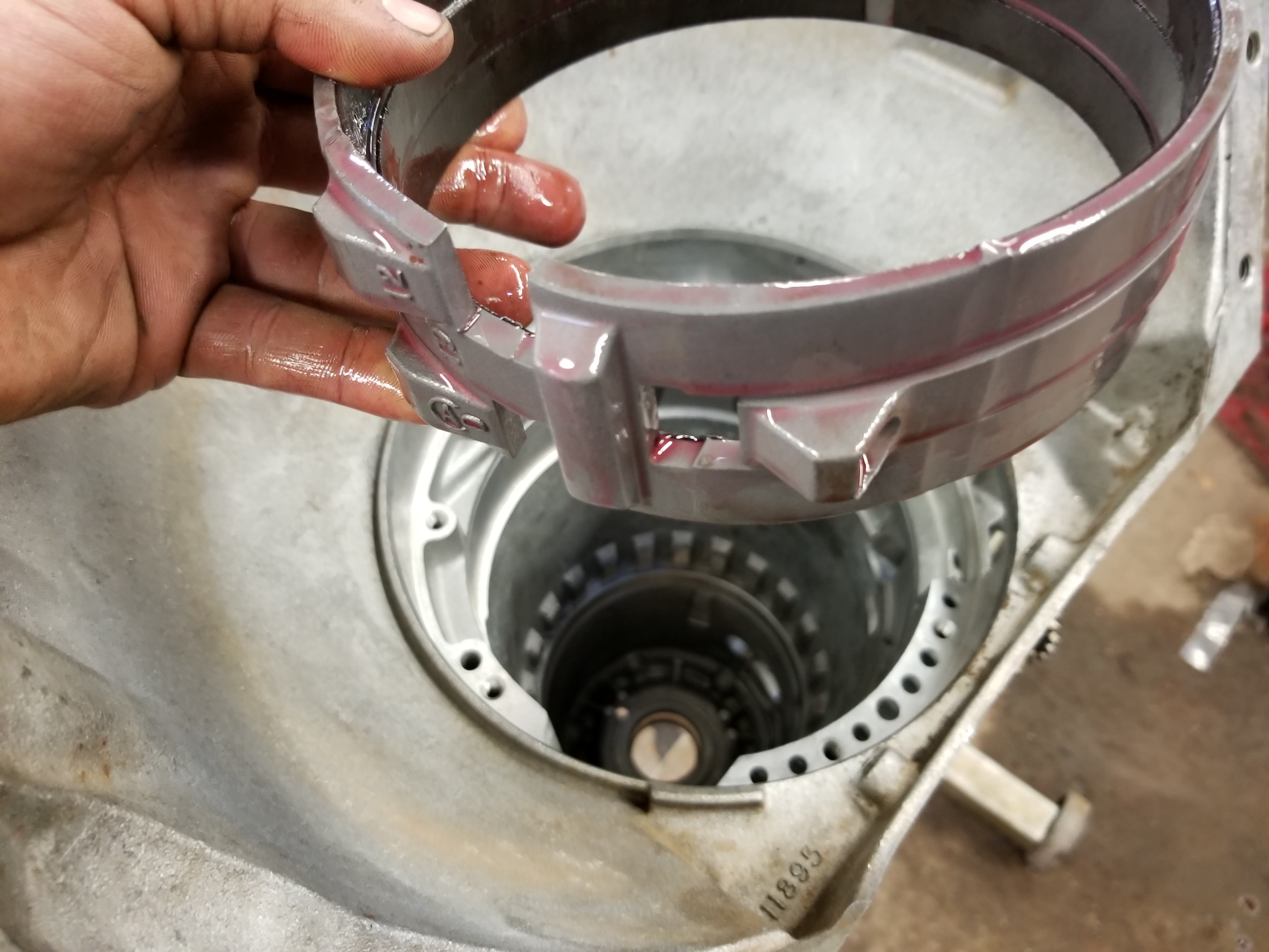
Install the Low/Revers band into the case paying attention to the "pocket" on the band which is actuated by the servo pin portruding through the valve body side of the case. The other two "pockets" are engaged by case lugs.

Install the center support spacer snap rings into the case above the band, making sure the opening of the snap ring faces the 9 o'clocl position as you peer into the case.

Here is the improved intermediate return spring assembly from C/K which replaces the stock one shown previously.

Install a new seal in the center support. This is where the cooler fitting goes.

This is another shot showing the correct orientation of the lip seals on the intermediate piston. They face DOWN into the bore on the center support.

Installing the new springs into the intermediate piston

The stronger intermediate piston return spring assembly shown left is much beefier than the flimsy stock piece on the right.

Another shot showing the difference in the "beefiness".
Last edited by ElQueF�r; 07-02-2018 at 02:56 PM.
 12-22-2018, 12:48 PM
#70
Yes it is in and working great.... On reverse it acts kind of funny but my reading has lead me to believe that I need to check and possibly adjust the length of the reverse servo pin to correct that problem.
I quit posting in this thread because it seemed like no one cared.
I quit posting in this thread because it seemed like no one cared.

 01-09-2019, 10:53 AM
#74
Teching In

Join Date: Jul 2018
Posts: 24
Likes: 0
Received 0 Likes
on
0 Posts
I appreciate the write up! I�m doing a Jake�s stage 3 rebuild in the garage, without special tools. Thank you for the detailed write up. I�m hung up due to a missing thrust bearing. Also due to the purchased transmission was rebuilt but has been sitting outside getting rained on, and now it taking it apart surface rust on most all the �hard parts�.
