
About ACE Racing Transmissions Converters
 01-12-2008, 01:10 AM
#1
FormerVendor
Thread Starter
I thought this would be a good time and place to introduce in fairly good detail what goes into the construction of our High Performance Torque Converters. Recently I took a trip over to our Converter shop and photographed several different styles and types of converters for review and discussion here. I'll talk about the different components as I go through. I can't get all the photos up tonight, so bear with me... I'll get them all up soon enough!
I'll start with the units that will be of the most interest to the enthusiasts here. These are our 9-1/2" Street Strip Converters.
Note: The Transmission side of the Converter is called the Bowl Side and the Engine side of the Converter is called the Front Cover.
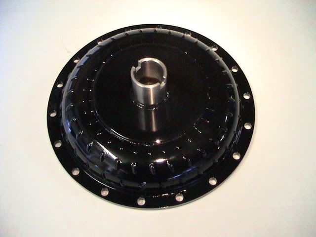
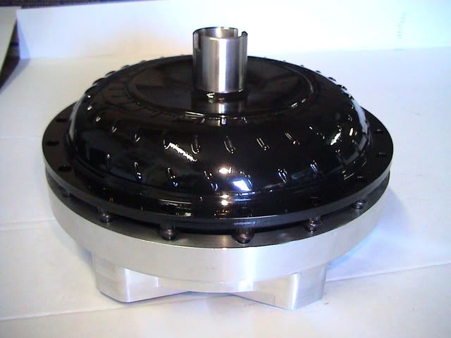
ACE Racing Transmissions 9-1/2" Street / Strip Torque Converter. This particular unit is a 3,000 RPM stall version. P/N - SS300060E
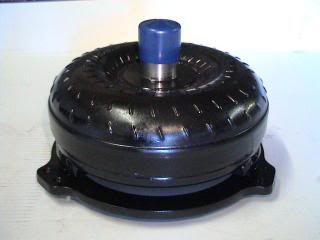
Inertia Ring and LSx Crankshaft Pilot Hub shown. Look closely, the Ring Bolts are torqued down and then welded into place. At that point, the Ring is then welded to the Pads it is sitting on. This is now one solid piece, not just two parts that have been bolted together!
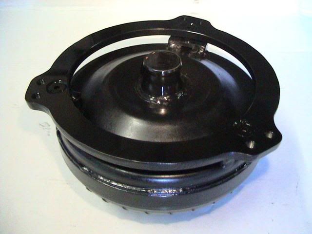
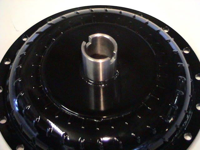
SS3000 with 4L60E Front Pump Hub.

If that is what the finished product looks like... here are some pics of a unit I pulled out of production in order to snap some pics for you guys. I'll start with the Front cover and work my way to the Bowl showing all of the internal components along the way.
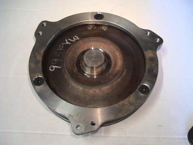
This particular unit is an SS4000350 being built for a customer with a TH350. The 1st thing to notice is the difference in the Crankshaft Pilot Hub in this unit compares to the LSX version. Then, notice how the Inertia Ring mounts differently to the Cover itself. Those are some of the subtle differences in these two Torque Converters.
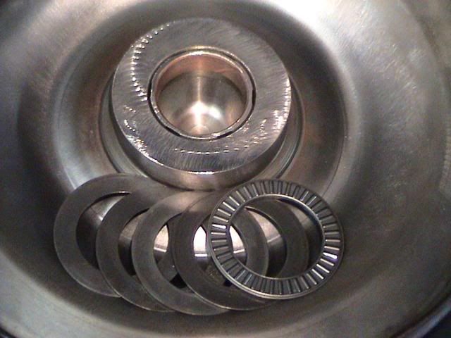
Front Cover with new Bushing, Hardened Shims and new Torrington Roller bearing... those parts support the Turbine. Notice the flat surface around the outside circumference. That is the area that the Converter Cutch engages when the TCC is commaned on by the PCM.

Close shot of the hardware.
TCC Piston assy.
This is a representative Piston and not the exact piece that would fit this converter... the correct part was in the Clutch Bonding Process when I was there. (Basically it was in a really friggin hot oven and I wasn't gonna touch it, so i grabbed another one!)
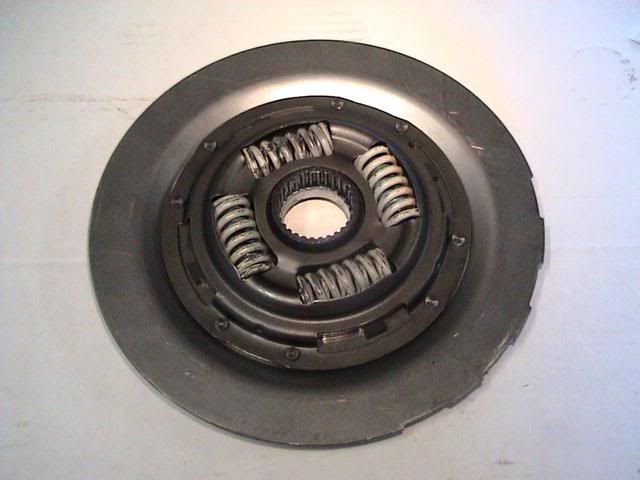
This is the Bowl side of the TCC Apply Piston. Notice the dampening springs. Some manufacturers build their units without these springs. Pistons without Dampening Springs can cause the Piston Hub or Input Shaft of the transmission to break when the TCC is applied in high torque loading situations.
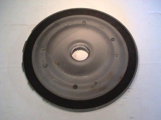
This is what the TCC Apply Piston looks like. This is the Disc side, it interacts with the Front Cover to provide Lock Up. So, imagine the front cover being bolted to the engine crankshaft, then the piston being applied compressing the single clutch disc. The piston is splined to the input shaft of the transmission. Think about it... the weakest link between the engines crankshaft and the trannys inputshaft is this one single clutch disc.
In simpler terms.... the energy flows from the crankshaft to the front cover to the clutch disc to the input shaft when the TCC is commanded to be locked up. (By comparisson, we use an 8 clutch set up in the 3/4 clutches on our 4L60E's.) You sure you want to make dyno pulls on your Single Disc Torque Converter while it's locked up?
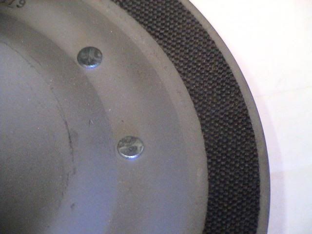
Factory woven clutch material on TCC piston.
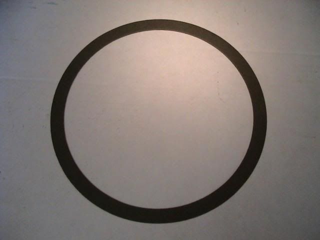
Pretty crappy pic of a different type of TCC material. This one is actually a Borg Warner High Energy type material.
The Turbine
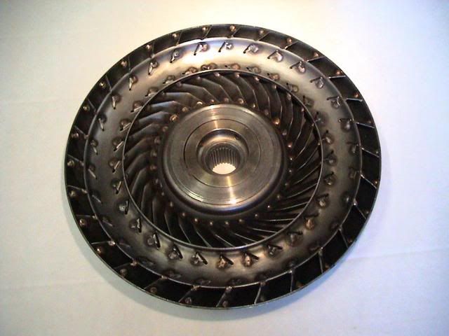
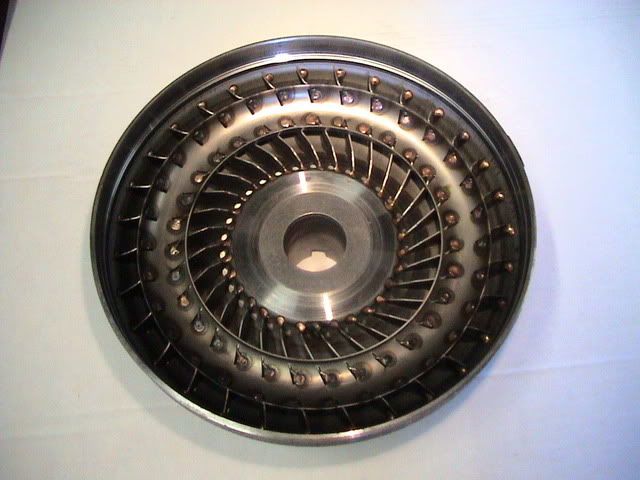
This is the Front Cover side of the Turbine. Look closely and you can see that all of the Fins are Tig Welded into place at each location.
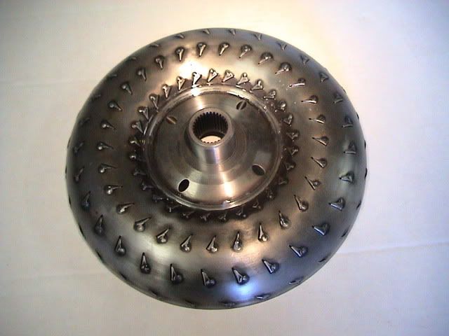
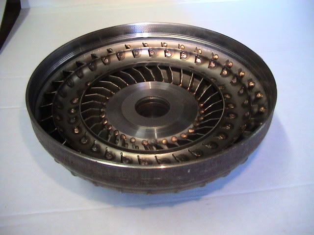
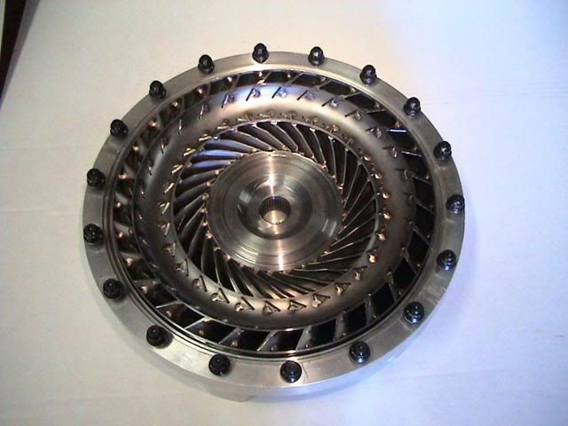
This is the Back Side or Bowl Side of the Turbine. Notice how each and every Fin is Tig Welded into place at multiple locations for added strength.
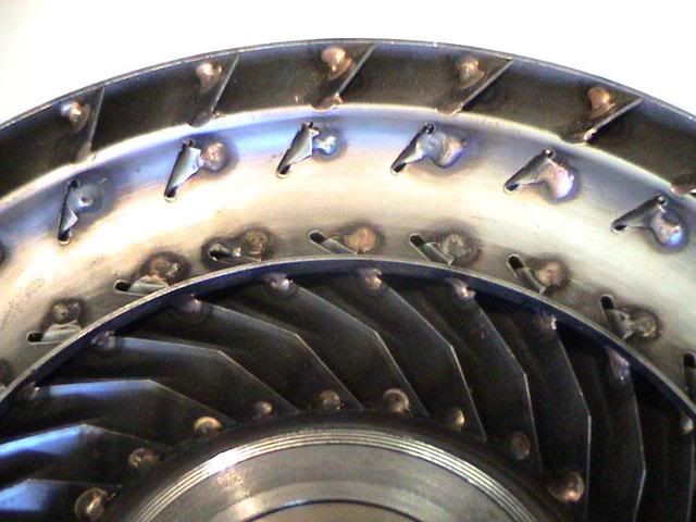
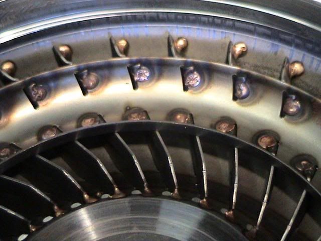
This close up photo shows in detail how each and every Fin is Tig Welded into place at multiple locations on the Turbine. (For those who are counting... that's a total of 10 locations per fin.)
The Stator
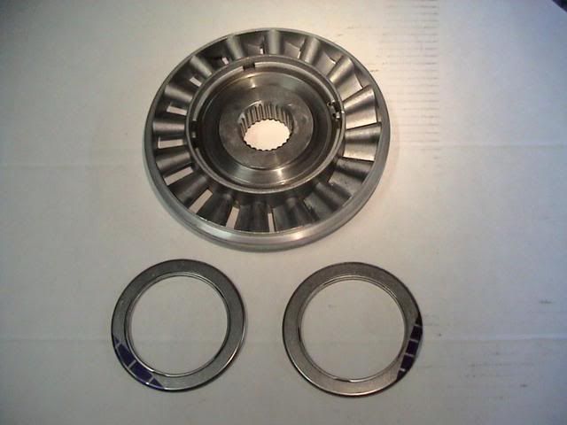
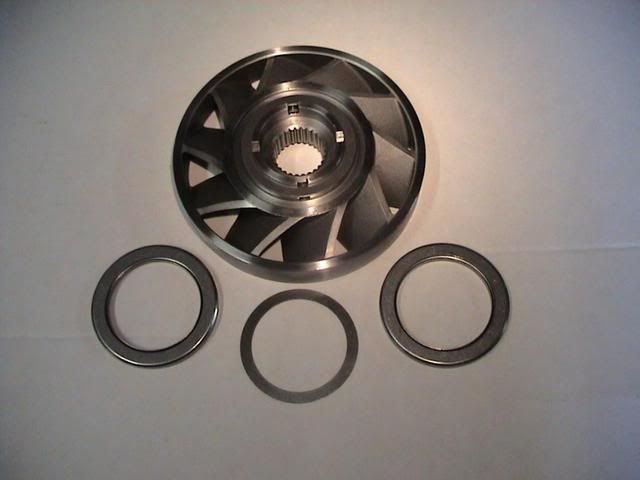
This is a photo of the Aluminum Stator that comes in all of our SS units. It utilizes a sprag. We can build Spragless Steel Stator units for max effort applications as well! Notice the 2 new Torrington Roller bearings that support the Stator.
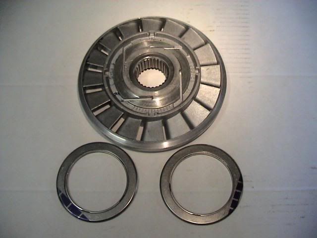
Opposite view of Stator.
The Bowl
Notice how each and every Fin is Tig Welded into place at multiple locations. Some of our units are Furnace Brazed as well as being Tigged. This simply adds an added level of insurance against fatigue.
A little better view of the bowl and its fins.
This is a close up photo showing how each and every Fin is Tig Welded into place in the Bowl, same as we do the Turbine.
More very soon! And the hardware gets better too!
It is my most sincere wish that this information helps to dispell misinformation, sparks discussion and takes some of the mystery out of "Stalls" for you guys!
g
I'll start with the units that will be of the most interest to the enthusiasts here. These are our 9-1/2" Street Strip Converters.
Note: The Transmission side of the Converter is called the Bowl Side and the Engine side of the Converter is called the Front Cover.
ACE Racing Transmissions 9-1/2" Street / Strip Torque Converter. This particular unit is a 3,000 RPM stall version. P/N - SS300060E
Inertia Ring and LSx Crankshaft Pilot Hub shown. Look closely, the Ring Bolts are torqued down and then welded into place. At that point, the Ring is then welded to the Pads it is sitting on. This is now one solid piece, not just two parts that have been bolted together!
SS3000 with 4L60E Front Pump Hub.
If that is what the finished product looks like... here are some pics of a unit I pulled out of production in order to snap some pics for you guys. I'll start with the Front cover and work my way to the Bowl showing all of the internal components along the way.
This particular unit is an SS4000350 being built for a customer with a TH350. The 1st thing to notice is the difference in the Crankshaft Pilot Hub in this unit compares to the LSX version. Then, notice how the Inertia Ring mounts differently to the Cover itself. Those are some of the subtle differences in these two Torque Converters.
Front Cover with new Bushing, Hardened Shims and new Torrington Roller bearing... those parts support the Turbine. Notice the flat surface around the outside circumference. That is the area that the Converter Cutch engages when the TCC is commaned on by the PCM.
Close shot of the hardware.
TCC Piston assy.
This is a representative Piston and not the exact piece that would fit this converter... the correct part was in the Clutch Bonding Process when I was there. (Basically it was in a really friggin hot oven and I wasn't gonna touch it, so i grabbed another one!)
This is the Bowl side of the TCC Apply Piston. Notice the dampening springs. Some manufacturers build their units without these springs. Pistons without Dampening Springs can cause the Piston Hub or Input Shaft of the transmission to break when the TCC is applied in high torque loading situations.
This is what the TCC Apply Piston looks like. This is the Disc side, it interacts with the Front Cover to provide Lock Up. So, imagine the front cover being bolted to the engine crankshaft, then the piston being applied compressing the single clutch disc. The piston is splined to the input shaft of the transmission. Think about it... the weakest link between the engines crankshaft and the trannys inputshaft is this one single clutch disc.
In simpler terms.... the energy flows from the crankshaft to the front cover to the clutch disc to the input shaft when the TCC is commanded to be locked up. (By comparisson, we use an 8 clutch set up in the 3/4 clutches on our 4L60E's.) You sure you want to make dyno pulls on your Single Disc Torque Converter while it's locked up?
Factory woven clutch material on TCC piston.
Pretty crappy pic of a different type of TCC material. This one is actually a Borg Warner High Energy type material.
The Turbine
This is the Front Cover side of the Turbine. Look closely and you can see that all of the Fins are Tig Welded into place at each location.
This is the Back Side or Bowl Side of the Turbine. Notice how each and every Fin is Tig Welded into place at multiple locations for added strength.
This close up photo shows in detail how each and every Fin is Tig Welded into place at multiple locations on the Turbine. (For those who are counting... that's a total of 10 locations per fin.)
The Stator
This is a photo of the Aluminum Stator that comes in all of our SS units. It utilizes a sprag. We can build Spragless Steel Stator units for max effort applications as well! Notice the 2 new Torrington Roller bearings that support the Stator.
Opposite view of Stator.
The Bowl
Notice how each and every Fin is Tig Welded into place at multiple locations. Some of our units are Furnace Brazed as well as being Tigged. This simply adds an added level of insurance against fatigue.
A little better view of the bowl and its fins.
This is a close up photo showing how each and every Fin is Tig Welded into place in the Bowl, same as we do the Turbine.
More very soon! And the hardware gets better too!
It is my most sincere wish that this information helps to dispell misinformation, sparks discussion and takes some of the mystery out of "Stalls" for you guys!
g
Last edited by Gilbert@Ace Racing; 01-12-2008 at 08:25 AM.
 01-15-2008, 08:50 PM
#2
FormerVendor
Thread Starter
Here is an example of a very high H/P unit that was recently built.
2,500 H/P Billet Front Cover Torque Converter
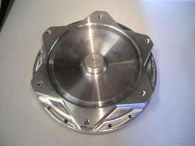
This is the front side (engine side) of the Front Cover.
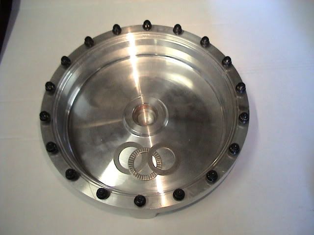
This is the inside of the Billet Aluminum Front Cover. Notice the ARP studs as this unit is a bolt together model. Note the 2 hardened selective shims and the new Torrington roller bearing. There is also a new Turbine Support bushing.
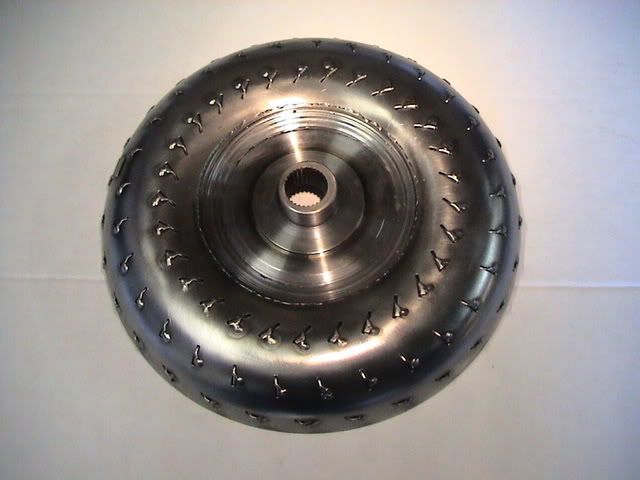
This is the Front Cover side of the Turbine. Look closely and you can see that all of the Fins are Tig Welded into place at each location.
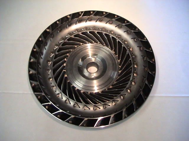
This is the Stator side of the Turbine. Notice how each and every fin is Tig Welded into place at multiple locations. It is very tedious and time consuming, but that's what it takes to build a Racing unit! Some units get Furnace Brazed too.
This photo shows the Turbine as it sits inside the Front Cover.
This is one trick piece! This is a Spragless Steel Stator. One way to make coarse changes in the stall speed of these and other units is to change the Stator to a part that has less or more Fins. Another way to accomplish this is to "cut" the Stator whereby more space is added between the Turbine and Stator by milling material from it. Note also the Stator support Bearings and selectable shim.
This is what the Steel Stator looks like as it sits inside the Turbine.

This is the inside of the Bowl 1/2 of the unit. Notice how all of the fins are Tigged at all every spot they can be welded. That keeps them from movng around under high loads at high RPM.

Bowl or Back cover. The Bowl, Billet Hub, Anti-Ballooning Plate and Mounting Ring are all assembled individually. Each piece is carefully inspected, the Stall speed is set and then final assembly begins. This is what the finished product looks like.
This gives you an idea of what the finished product looks like. This particular unit will go into an Outlaw 10.5 car very soon.
And that's one way to build a 2,500 H/P Racing Converter. Lot's of companies around the country are building Racing converters... some companies are building them by purchasing Kits from Industry Manufactures... not unlike an Engine shop buys a rotating assy and pistons for example... and then other converter companies own CNC mills and are cutting their own Front Covers. This unit was spec'd out far a particular combination.
g
2,500 H/P Billet Front Cover Torque Converter
This is the front side (engine side) of the Front Cover.
This is the inside of the Billet Aluminum Front Cover. Notice the ARP studs as this unit is a bolt together model. Note the 2 hardened selective shims and the new Torrington roller bearing. There is also a new Turbine Support bushing.
This is the Front Cover side of the Turbine. Look closely and you can see that all of the Fins are Tig Welded into place at each location.
This is the Stator side of the Turbine. Notice how each and every fin is Tig Welded into place at multiple locations. It is very tedious and time consuming, but that's what it takes to build a Racing unit! Some units get Furnace Brazed too.
This photo shows the Turbine as it sits inside the Front Cover.
This is one trick piece! This is a Spragless Steel Stator. One way to make coarse changes in the stall speed of these and other units is to change the Stator to a part that has less or more Fins. Another way to accomplish this is to "cut" the Stator whereby more space is added between the Turbine and Stator by milling material from it. Note also the Stator support Bearings and selectable shim.
This is what the Steel Stator looks like as it sits inside the Turbine.
This is the inside of the Bowl 1/2 of the unit. Notice how all of the fins are Tigged at all every spot they can be welded. That keeps them from movng around under high loads at high RPM.
Bowl or Back cover. The Bowl, Billet Hub, Anti-Ballooning Plate and Mounting Ring are all assembled individually. Each piece is carefully inspected, the Stall speed is set and then final assembly begins. This is what the finished product looks like.
This gives you an idea of what the finished product looks like. This particular unit will go into an Outlaw 10.5 car very soon.
And that's one way to build a 2,500 H/P Racing Converter. Lot's of companies around the country are building Racing converters... some companies are building them by purchasing Kits from Industry Manufactures... not unlike an Engine shop buys a rotating assy and pistons for example... and then other converter companies own CNC mills and are cutting their own Front Covers. This unit was spec'd out far a particular combination.
g
03-17-2008, 05:33 PM
#3
FormerVendor
Thread Starter
I brought this thread back today because of all the questions we have had about our converters in the last week and today!
If you have any questions feel free to post up or call me!
g
If you have any questions feel free to post up or call me!
g
06-24-2008, 09:48 PM
#4
FormerVendor
Thread Starter
Tonight I received an inquiry regarding our Torque Converters. I am very frequently referring potential clients to this thread that I had generated several months ago for that very purpose.
One thing I forgot to add to the original write up is that we can build a unit very, very similar to the billet aluminum front cover unit. It would utilize the spragless steel stator and all the goodies, however it would utilize a traditional steel front cover. And it would come in much, much less expensive.
Also, notice how the very same craftsmanship applies to the 9-1/2" unit that applies to the High End Racing unit! No corners are cut, regardless of the unit, ever.
If you have any questions about our Torque Converters and the Personalized Craftsmanship that goes into them, just give me a shout.
g
Last edited by Gilbert@Ace Racing; 06-24-2008 at 10:57 PM.