Folks with Luk LS7 clutch issue, pls chime in
 04-22-2017, 04:48 PM
#1
TECH Regular
Thread Starter
Here are so many threads now about peoples having issues with their Luk 04-216 clutch kit, so i think it´s on time to put them all together to one thread, what did you all think about?
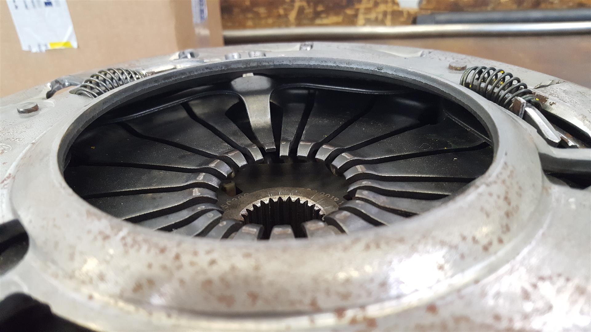
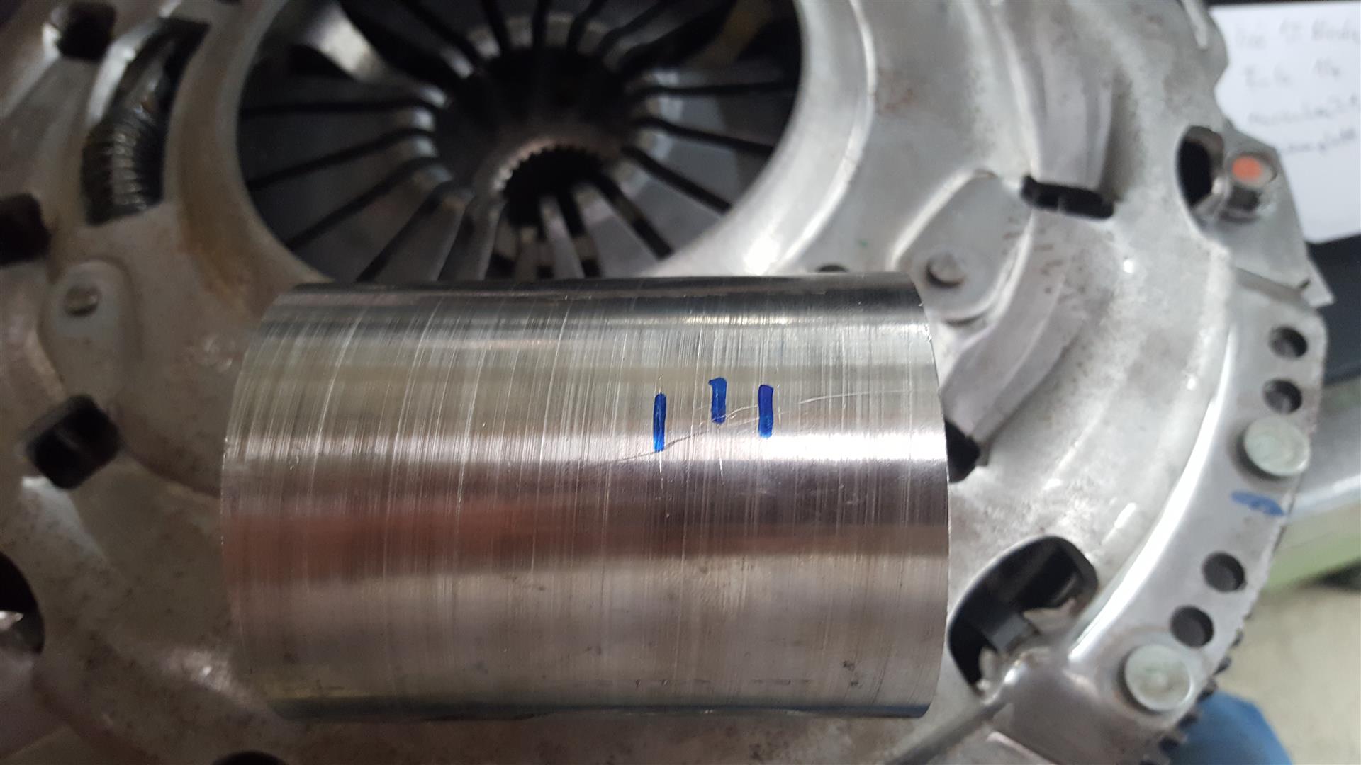
I have had no vibs in the past, but the concave surface on flywheel and pressure plate gives me some food for thoughts and i also controlled the run out on my lathe and found some other irregularities like sidestroke...
I turned both surfaces flat and that creates a theoretical gap of 1,5mm between pp and flywheel in the disc area, so i wanted to compensate this by turning the contact surface from pp to flywheel by another 1,5mm and then, after mounting all parts together, the springloaded fingers goes down to the deepest point they can go, short before they get in contact with the disc, a correct engagement from the clutch wasn´t possible, so what was wrong here?
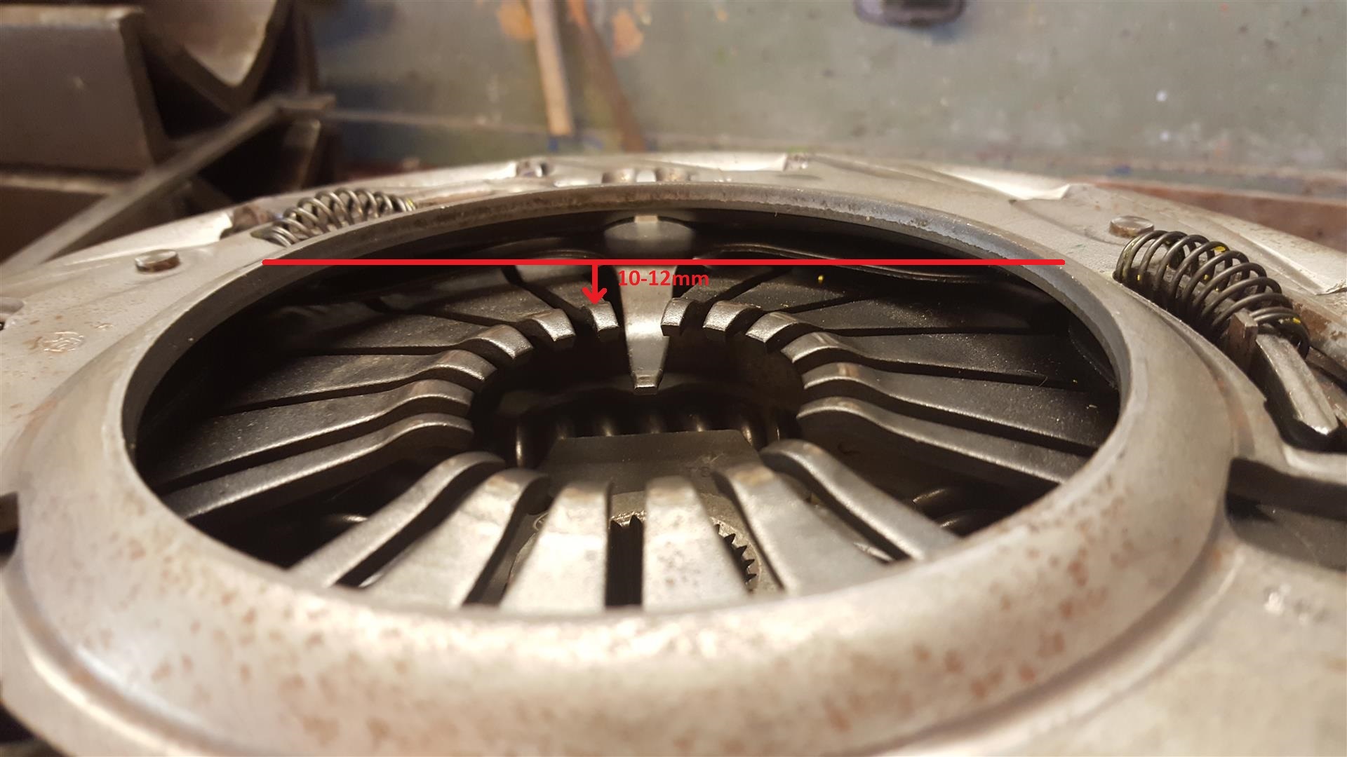
Here are 2 pics, 1.as it was after turning to the supposed right specs, 2.with 1,5mm washers between pp and flywheel, like it was before without machining on the contact surface and i filled in the measurement of it now:
This all tells me, that the culprit must be the SAC system, which is a variable to adapt new or other circumstances, here to read in english:
http://www.schaeffler.com/remotemedi...ase_system.pdf
So i phoned to an engineer here in Luk headquarter Bühl/BW/Germany, but he told me, that the LS7 clutch system was developed and produced in USA or Mexico, so he has no data sheets by hand and can not help me with my issue to find the right specs i need for fully functional clutch system!
I should write a letter perhaps a E-Mail with pics and videos, they will send it to the right location in the US, but maybe have also to send in my complete set for troubleshooting, this is to much stress, time and money for me, shipping a 50pound package to the manufacturer, but this can help us in the future to get rid of (all) our issues with the kit, someone here must do the first step in this way or better more peoples does this...
Another reason for vibs can be loosen the bolts from pp in the wrong sequence, bec of stronger loaded spring fingers then in normal pp w/o the SAC system, so the pp can be distorted if not loosened in the star pattern way, like we have tightened them, maybe only a half rotation on every bolt, not loosen one of them completly outside or use their special tool, so that the preloaded pp stays during the swap in the right position, that is also highly recommended, he told me!
Here is another tutorial from Luk and explaining about the special tool in english:
http://www.schaeffler.com/remotemedi...ech_sac_en.pdf
So it might be possible, that some of us created their issue by themselves, idk...
With this information, i hope i can bring some light in the darkness about the specialty from Luk LS7 SAC clutch systems, will try to keep mine in the right direction and report back, about the results of it!
Greetz,
Ron
I have had no vibs in the past, but the concave surface on flywheel and pressure plate gives me some food for thoughts and i also controlled the run out on my lathe and found some other irregularities like sidestroke...
I turned both surfaces flat and that creates a theoretical gap of 1,5mm between pp and flywheel in the disc area, so i wanted to compensate this by turning the contact surface from pp to flywheel by another 1,5mm and then, after mounting all parts together, the springloaded fingers goes down to the deepest point they can go, short before they get in contact with the disc, a correct engagement from the clutch wasn´t possible, so what was wrong here?
Here are 2 pics, 1.as it was after turning to the supposed right specs, 2.with 1,5mm washers between pp and flywheel, like it was before without machining on the contact surface and i filled in the measurement of it now:
This all tells me, that the culprit must be the SAC system, which is a variable to adapt new or other circumstances, here to read in english:
http://www.schaeffler.com/remotemedi...ase_system.pdf
So i phoned to an engineer here in Luk headquarter Bühl/BW/Germany, but he told me, that the LS7 clutch system was developed and produced in USA or Mexico, so he has no data sheets by hand and can not help me with my issue to find the right specs i need for fully functional clutch system!
I should write a letter perhaps a E-Mail with pics and videos, they will send it to the right location in the US, but maybe have also to send in my complete set for troubleshooting, this is to much stress, time and money for me, shipping a 50pound package to the manufacturer, but this can help us in the future to get rid of (all) our issues with the kit, someone here must do the first step in this way or better more peoples does this...
Another reason for vibs can be loosen the bolts from pp in the wrong sequence, bec of stronger loaded spring fingers then in normal pp w/o the SAC system, so the pp can be distorted if not loosened in the star pattern way, like we have tightened them, maybe only a half rotation on every bolt, not loosen one of them completly outside or use their special tool, so that the preloaded pp stays during the swap in the right position, that is also highly recommended, he told me!
Here is another tutorial from Luk and explaining about the special tool in english:
http://www.schaeffler.com/remotemedi...ech_sac_en.pdf
So it might be possible, that some of us created their issue by themselves, idk...
With this information, i hope i can bring some light in the darkness about the specialty from Luk LS7 SAC clutch systems, will try to keep mine in the right direction and report back, about the results of it!
Greetz,
Ron
Last edited by Choppy_Idle; 04-22-2017 at 04:58 PM.
 04-26-2017, 02:24 PM
#2
TECH Regular
Thread Starter
It looks like all users here are pleased with their Luk set up, so i put in some numbers to compare, maybe it´s easier to chime in and reply?!
First of all some pics, so explaining might be a little bit easier for me and we are all talking about the same measurement and a how to get it:
Now i tried different settings in regards to the self adjusting mechanism, so on the dead stop between pp and disc, i can put the indicator with a screwdriver in direction against the small spring or away from her, in the opposite direction!
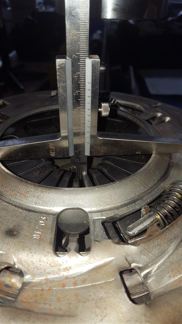
When i put the indicator against the spring, hold him in place and open the valve from hydraulic press to a fully disengage in start position, the fingers will come up to 8mm like shown in pic 1 with the deepth gauge and the preload from indicator will also still stay in this position, where i put him before with the screwdriver!
So when i start again a release of the clutchdisc and pump the hydraulic press down, before it will come to engage, the indicator is slowly going away from his position and would rest nearly the oem position when clutch was new!
I tried this a few times, ever the same result, but if you press down to the dead stop, he will go under the oem markings from me on the pp!
If i go the opposite way and put the indicator away from the spring all the way to the stop, he will leave in this position, what ever i try to do and spring fingers are so deep down now at fully disengage, that a release of the clutchdisc isn´t possible, you are short before dead end between pp and disc with the fingers!
So this might be, what they want to tell us about the function of SAC and why it is strongly recommended, to use their "position holding tool", that there is no chance for the SAC system to come up from the dead end position, the springs does her work too, so you must have a preload and what´s the right position, the SAC will determine by herself!
In numbers i have now with 1.5mm shims between pp and mounting area on flywheel, to come back to the origin specs from before, bec i might be wrong, turning this surface down to 1.5mm to get in balance to the others:
Fingers distance to case like shown in pic 1 is 14mm, the clutch release begins at 21mm and is fully engaged with a gap from around 2-3mm on the disc at 28mm, so i think, there isn´t more travel then 14mm needed from the slave to a fully engage from clutch, oem new is between 10-12mm at the starting point on pp spring fingers!
Who has also numbers to share with?
Btw: Hope my theory about function of SAC System is right?!
Regards
Ron
First of all some pics, so explaining might be a little bit easier for me and we are all talking about the same measurement and a how to get it:
Now i tried different settings in regards to the self adjusting mechanism, so on the dead stop between pp and disc, i can put the indicator with a screwdriver in direction against the small spring or away from her, in the opposite direction!
When i put the indicator against the spring, hold him in place and open the valve from hydraulic press to a fully disengage in start position, the fingers will come up to 8mm like shown in pic 1 with the deepth gauge and the preload from indicator will also still stay in this position, where i put him before with the screwdriver!
So when i start again a release of the clutchdisc and pump the hydraulic press down, before it will come to engage, the indicator is slowly going away from his position and would rest nearly the oem position when clutch was new!
I tried this a few times, ever the same result, but if you press down to the dead stop, he will go under the oem markings from me on the pp!
If i go the opposite way and put the indicator away from the spring all the way to the stop, he will leave in this position, what ever i try to do and spring fingers are so deep down now at fully disengage, that a release of the clutchdisc isn´t possible, you are short before dead end between pp and disc with the fingers!
So this might be, what they want to tell us about the function of SAC and why it is strongly recommended, to use their "position holding tool", that there is no chance for the SAC system to come up from the dead end position, the springs does her work too, so you must have a preload and what´s the right position, the SAC will determine by herself!
In numbers i have now with 1.5mm shims between pp and mounting area on flywheel, to come back to the origin specs from before, bec i might be wrong, turning this surface down to 1.5mm to get in balance to the others:
Fingers distance to case like shown in pic 1 is 14mm, the clutch release begins at 21mm and is fully engaged with a gap from around 2-3mm on the disc at 28mm, so i think, there isn´t more travel then 14mm needed from the slave to a fully engage from clutch, oem new is between 10-12mm at the starting point on pp spring fingers!
Who has also numbers to share with?
Btw: Hope my theory about function of SAC System is right?!
Regards
Ron
04-26-2017, 06:12 PM
#3
GM spec is 0.550" (13.97mm) to clutch release, which basically all LS compatible clutches are designed to with few exceptions; some double or triple disc aftermarket designs have the release point at 0.450". Maximum travel in most cases is the same as GM spec, which is 0.750". I appreciate all the time and effort you put into experimentation, but these dimensions are standardized and are just one email or phone call (to the right person) away.
04-26-2017, 07:35 PM
#4

I too appreciate the work, still waiting to resolve my driveshaft issues before I can dig back into this one. I still am struggling to see how this would cause the vibration many seem to get in the 2-3k range, especially when the SAC mechanism "should" be the same across the LS platform. Maybe I am thick on this topic? My stock LS1 and cammed LS3 were all pretty buttery in front of my T56...but this LS6 seems to need that dual mass flywheel moreso than others.
04-26-2017, 08:04 PM
#5
Looking at old C5Z posts, I did notice that a significant number of people that reported vibration had actually bent their T-56 input shafts trying to do clutch swaps, and when they replaced the input shaft, the vibration went away. So that's a possibility here.

Trending Topics
04-27-2017, 07:05 AM
#8
TECH Apprentice

Join Date: Jun 2016
Location: GA
Posts: 350
Likes: 0
Received 0 Likes
on
0 Posts
It actually happens a lot. Lot of us jack stand workers dont have a transmission or motorcycle jack. So most people muscle it in a out without any real support, relying on the input shaft to hold it in place. The only savior is the dowels pins in our bell housings, but they are only a half inch long or so. I think this was the argument I was making with Ajoos? His video to me show way to much play imo. Mine after being rebuilt had nothing like that and my vibes up to 105 is almost non existent compared to before.
04-27-2017, 09:40 AM
#9
Yeah, but the shop I used has lifts, tranny jack, etc. and lots of experience with German cars so I will reasonably assume (from experience watching him) a fair level of care. That said, anyone can make a mistake, and bending that pressure plate also has a ring to it...I can see how that would be pretty easy to do.
04-28-2017, 02:34 AM
#11
TECH Regular
Thread Starter
Thanks Fuzzy, that you put in some numbers here, hope some folks will follow your good example!
But how much travel the slave does with the pmc willwood or tilton master, someone checked this?
Greetz
Ron
But how much travel the slave does with the pmc willwood or tilton master, someone checked this?
Greetz
Ron
Last edited by Choppy_Idle; 04-28-2017 at 02:42 AM.
04-28-2017, 09:50 AM
#12
If you want to calculate how much linear travel an arbitrary master cylinder diameter will provide, solve using the volume ratio of the master and the slave. GM, Wilwood, Tilton, and McLeod master cylinders all travel 1.100". If a slave is designed to travel 0.550" when driven by the amount of fluid in a 0.750" diameter, 1.100" long cylinder, a 0.875" (7/8") bore master will provide 0.749" travel. Note that this is a theoretical maximum and does not account for seal blow-by, leakage, compressible bubbles in the fluid, or hose expansion. By contrast, a 0.812" (13/16") master will provide 0.645" maximum travel.
Although McLeod and other companies recommend a 0.750" master because it theoretically provides sufficient travel to completely actuate the pressure plate and minimizes pedal effort, I disagree because 0.750" does not provide enough margin to account for non-optimal real world conditions. However, the 0.875" master in the PMC is excessive and requires 36.1% more force to actuate. Therefore I have found that the best compromise is a 0.812" master, which provides plenty of margin and only requires 17.2% more pedal effort.
17.2% and 36.1% may not sound like a lot, but it's very noticeable. If the pedal with 0.750" master required 65 lbs force, installing a 0.812" master will increase required force to 76 lbs. Likewise, a 0.875" master will increase required pedal effort to 88 lbs. Although most of you can leg press 125 lbs (per leg) or more, remember that during hard acceleration you may have 0.7G or more straight back resisting your leg. So that pedal effort requirement increases.
Last edited by FuzzyLog1c; 04-28-2017 at 10:34 AM.
05-04-2017, 03:38 PM
#13
Launching!
Join Date: Aug 2004
Location: Crowley, Texas
Posts: 271
Likes: 0
Received 0 Likes
on
0 Posts

I bought the LUK LS7 clutch kit for my 06 V and I have had issues with my setup. I replaced the shifter (Hurst from Brian) at the same time that I did the clutch. I have noticed that the clutch releases very close to the floor and there is a catch point (hard to explain) on the shifter between shifts... Meaning, you aren't going to power shift this thing even if you tried. It is probably a good thing I can't power shift it, but getting this in gear just feels very hard and requires quite a bit of leverage to get past the catch point. It does not go into gear like butter. I've seen other people say the same thing so I've just lived with it as I haven't felt like pulling the trans back out to really look at it. Anyways, no vibrations on my end. I pulled the transmission apart because of a vibration. Turns out the dual mass flywheel was coming apart. All is well in the vibration department now.
05-04-2017, 03:47 PM
#14
TECH Regular
Thread Starter
They told, you have try to get in every Gear without pushing the clutch pedal and without engine running, then you will know, its the clutch or the trans...
Btw, i was not a fan of the ultrashort version from Brians shifter and send it back, made my own version between oem and Hurst in the middle way of them!
Greetz
Ron
Btw, i was not a fan of the ultrashort version from Brians shifter and send it back, made my own version between oem and Hurst in the middle way of them!
Greetz
Ron
05-04-2017, 03:57 PM
#15
I bought the LUK LS7 clutch kit for my 06 V and I have had issues with my setup. I replaced the shifter (Hurst from Brian) at the same time that I did the clutch. I have noticed that the clutch releases very close to the floor and there is a catch point (hard to explain) on the shifter between shifts... Meaning, you aren't going to power shift this thing even if you tried. It is probably a good thing I can't power shift it, but getting this in gear just feels very hard and requires quite a bit of leverage to get past the catch point. It does not go into gear like butter. I've seen other people say the same thing so I've just lived with it as I haven't felt like pulling the trans back out to really look at it. Anyways, no vibrations on my end. I pulled the transmission apart because of a vibration. Turns out the dual mass flywheel was coming apart. All is well in the vibration department now.
The shifter probably doesn't have anything to do with the grab you're feeling. It sounds more like a fluid/synchro issue.
1. Make sure your clutch is thoroughly bled and that no air was hiding when you did the initial bleed.
2. What trans fluid are you running? Subbing a quart of gear oil in the ATF sometimes helps to "slow the synchros down" allowing you to slide into gear more smoothly. Redline advocates this pretty directly (https://www.redlineoil.com/Products.aspx?pcid=7). I used Amsoil 75w90 when I did it years ago.
My 2nd gear currently has a little catch in it too. The fluid probably has 70k on it and the clutch hasn't been bled in 60k. I'm probably due for both. The trans could definitely use a refresher though.
05-05-2017, 07:39 AM
#16
TECH Apprentice
Join Date: Jun 2016
Location: GA
Posts: 350
Likes: 0
Received 0 Likes
on
0 Posts
05-06-2017, 05:12 PM
#17
TECH Regular
Thread Starter
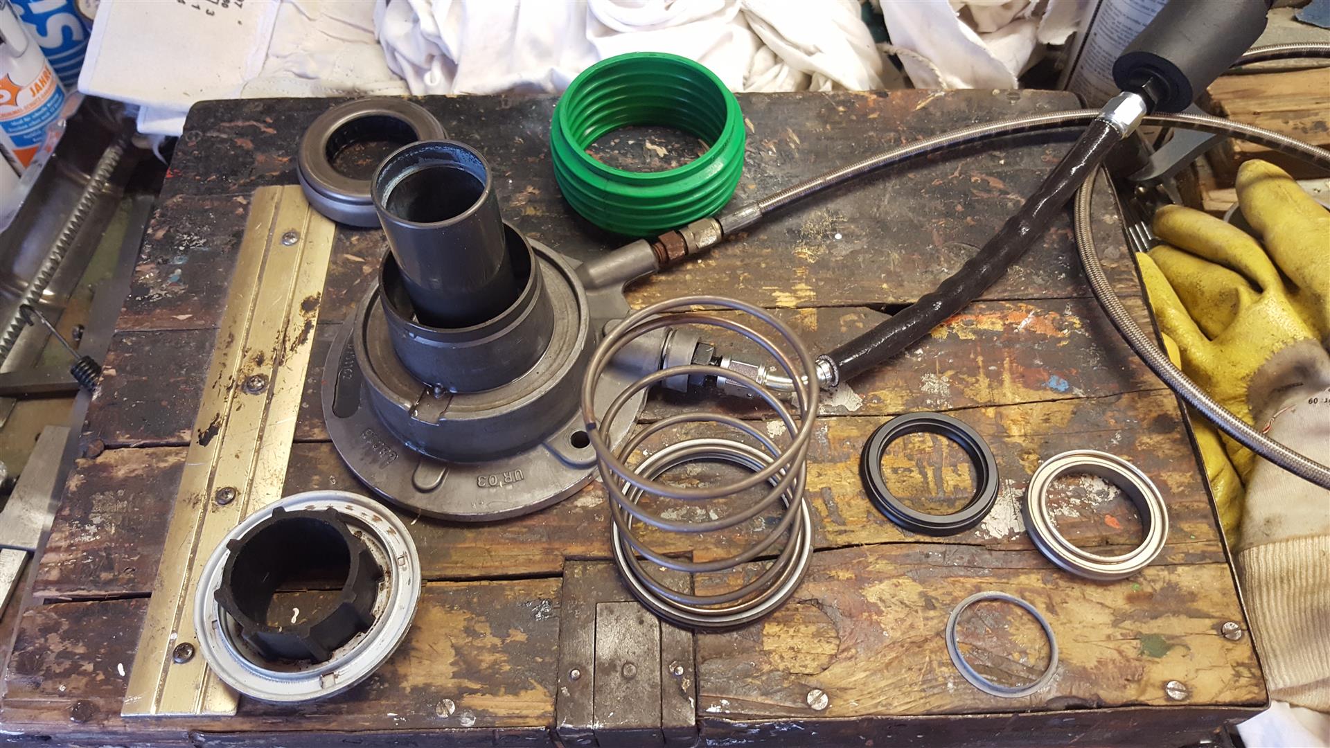
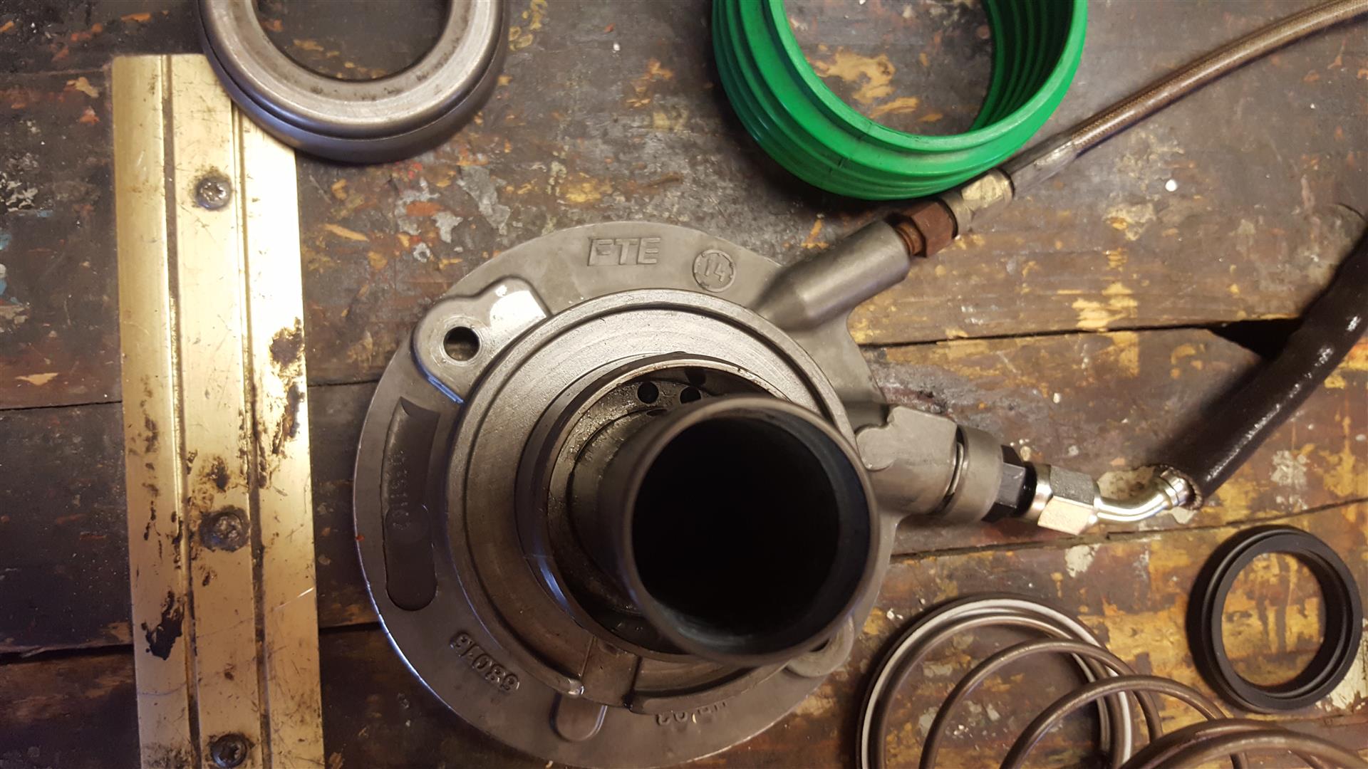
Next disaster here, looks like i´m overstroked the slave and the piston comes out...
Want to verify Fuzzy´s measurements like the stroke of .750" with the .875" Tilton made by pmc and simulated the spring loaded fingers from the pp with my special tool, to put the slave in his rear dead end, but won`t work as expected, after pushing the clutch pedal smoothly by hand the brake fluid comes out of the green boot, bec everything was closed and the lines overfilled with fluid, then i see that here:
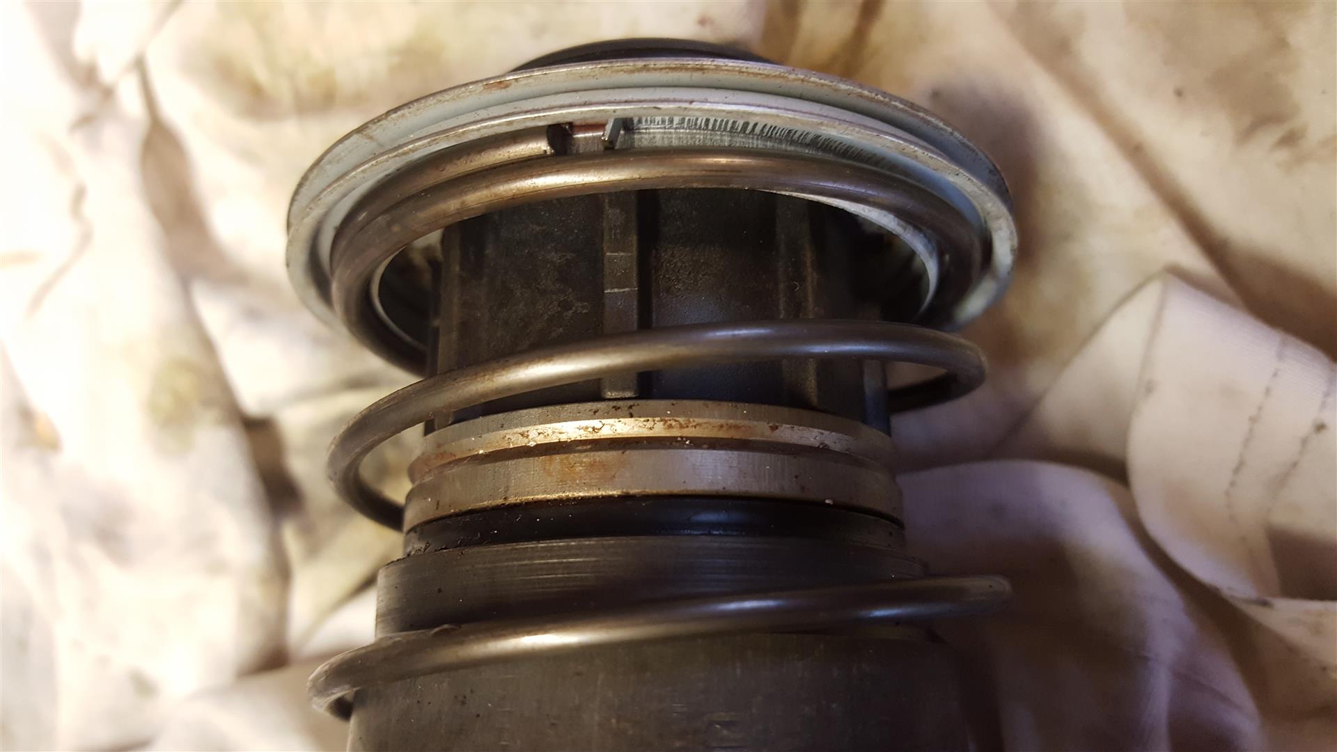
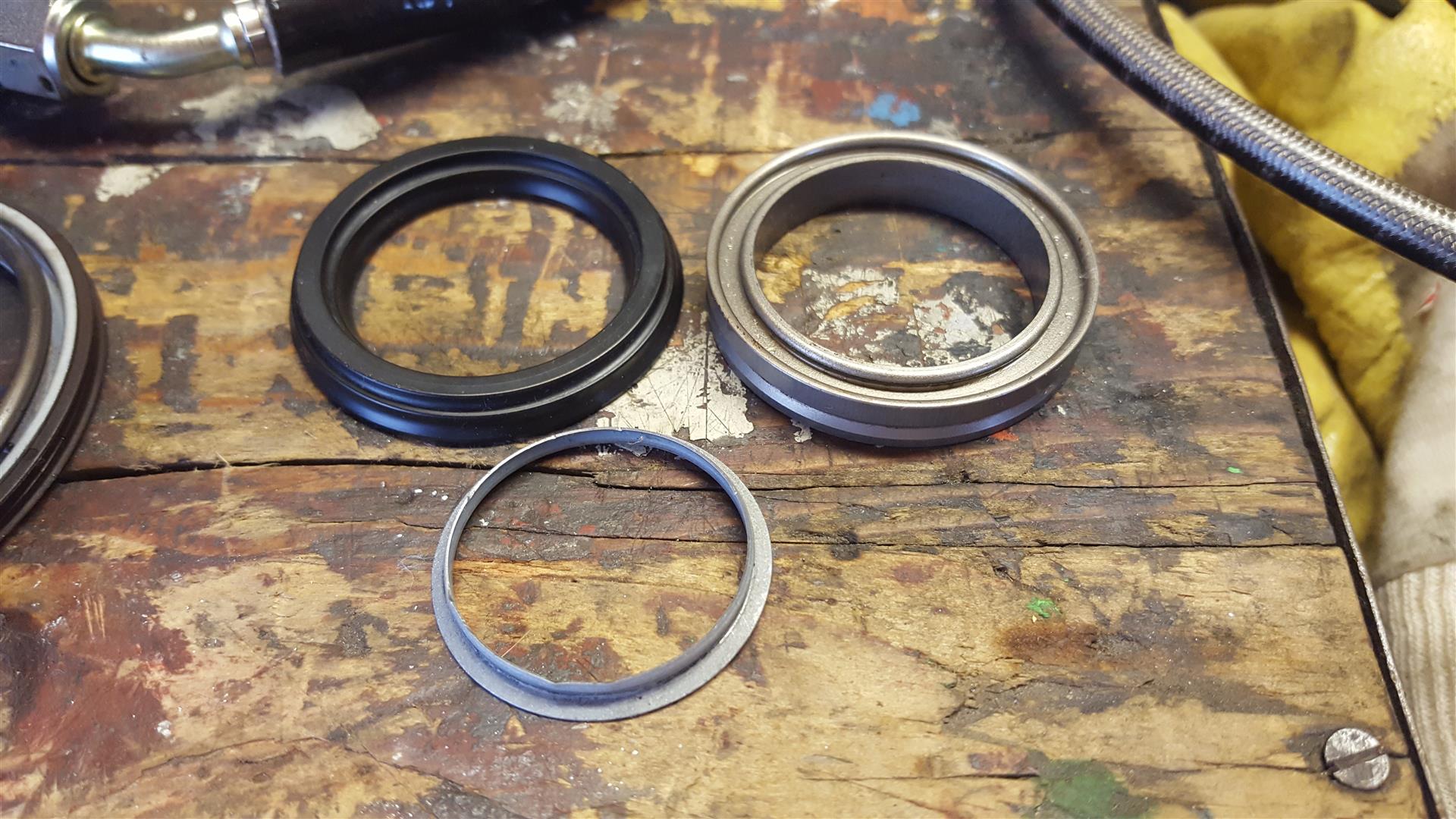
Can someone here confirm, that the metalring with the v-groove is the piston from the slave and he is thrown out?
Greetz
Ron
Want to verify Fuzzy´s measurements like the stroke of .750" with the .875" Tilton made by pmc and simulated the spring loaded fingers from the pp with my special tool, to put the slave in his rear dead end, but won`t work as expected, after pushing the clutch pedal smoothly by hand the brake fluid comes out of the green boot, bec everything was closed and the lines overfilled with fluid, then i see that here:
Can someone here confirm, that the metalring with the v-groove is the piston from the slave and he is thrown out?
Greetz
Ron
05-15-2017, 12:51 PM
#20
TECH Regular
Thread Starter
Thanks for the link Vroom, now put the slave together:
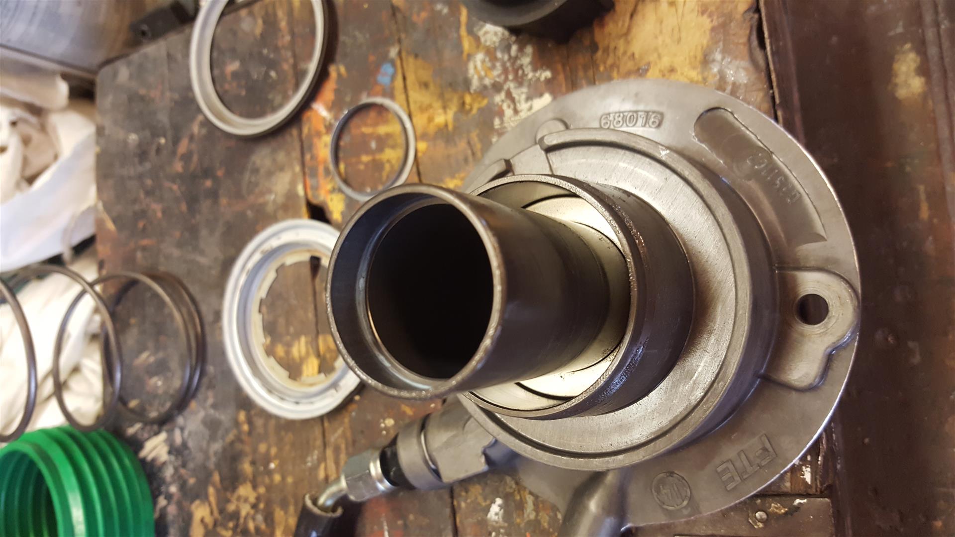
Now hope this issue is solved and i get no leaking on it...
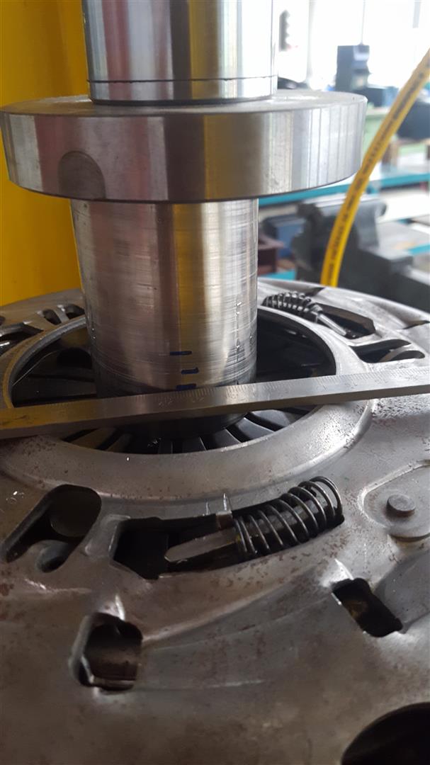
Next step, measuring distance from mounting area trans to clutch fingers:
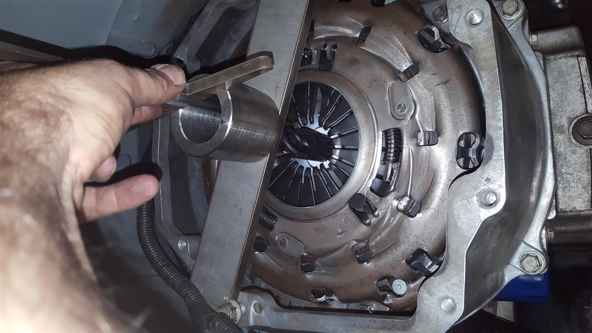
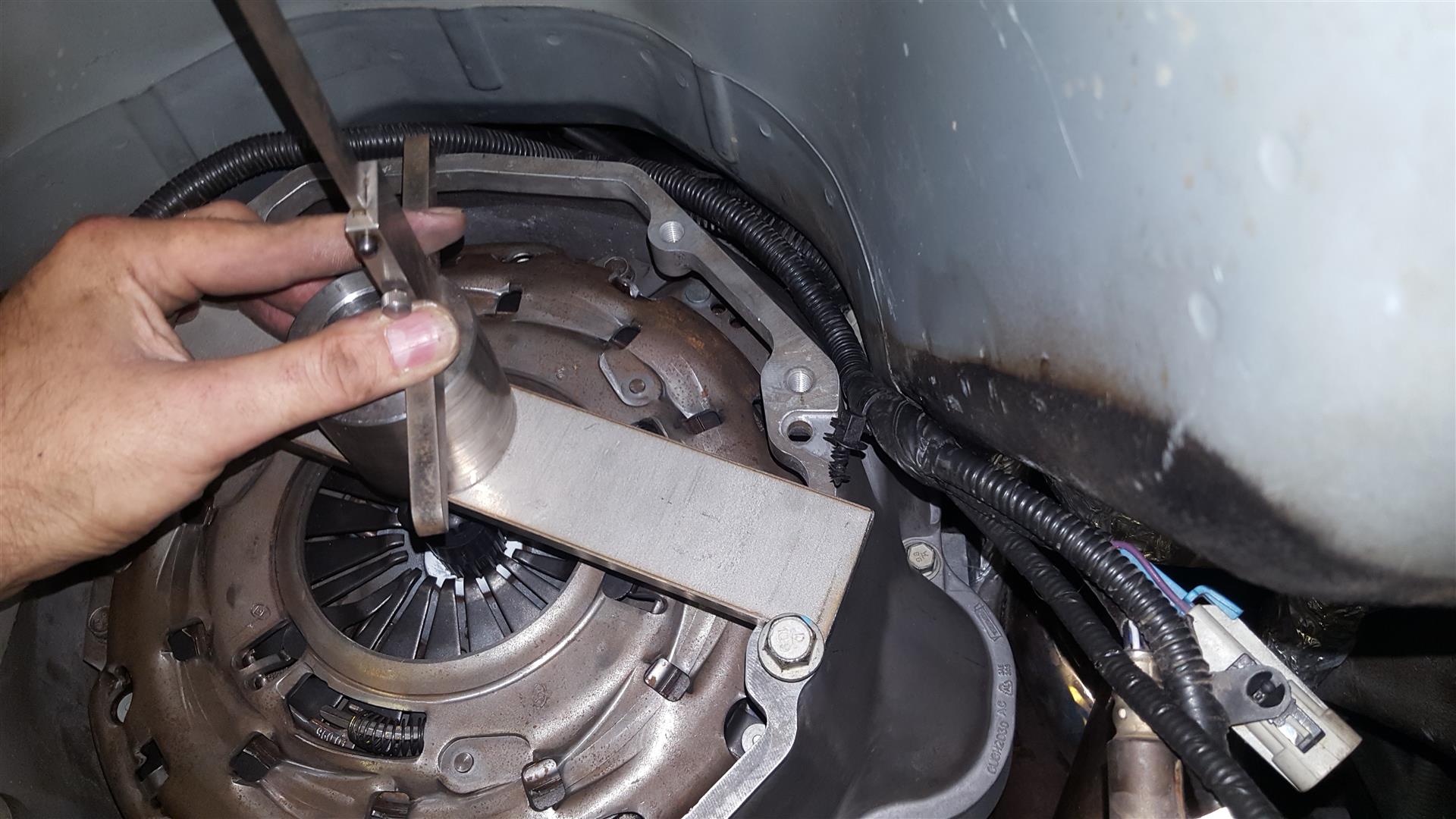
And at the end of the day, clutch is back on it´s place:
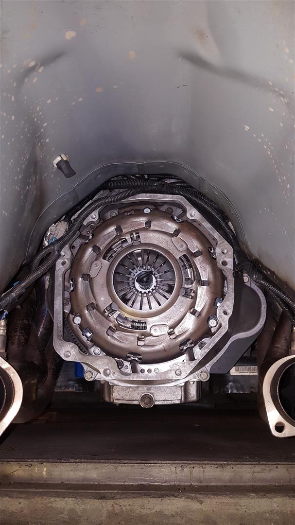
Greetz
Ron
Now hope this issue is solved and i get no leaking on it...
Next step, measuring distance from mounting area trans to clutch fingers:
And at the end of the day, clutch is back on it´s place:
Greetz
Ron