
Wiring and Fuses for Radiator Fans
 03-03-2009, 01:52 PM
#1
TECH Resident
Thread Starter

I'm going to wire my dual fans like the Fbody diagram. I see they use a 40 amp and a 10 amp fuse, but it seems difficult to find fuses and fuse holders rated higher than about 30 amps short of going to another style of fuse (Like cartridge fuses). Any suggestions?
Thanks,
Andy1
Thanks,
Andy1
 03-04-2009, 12:14 AM
#4
Depends on what you are looking to do. If you still need to get a fusebox/center for your conversion I would hit the junkyards. The mid 90`s and newer GM`s have fuse boxes with standard and maxi fuses. I don`t think they make a standard ATO fuse in a 40A rating, but the maxi fuses are available in 30A, 40A, 60A, and ????
If you already have the rest of the fuses figured out you can use a standard ATO fuse by running 2 20A fuses in parallel.
If you already have the rest of the fuses figured out you can use a standard ATO fuse by running 2 20A fuses in parallel.
03-04-2009, 06:29 AM
#5
Wal Mart carries maxi fuse holders that go up to 80 amps or more. They have them in the car stereo aisle
i got a 4 fuse holder from the place below that I use as a junction box between my alternater, battery and the chassis buss. That left me a separate circuit at the front of the car just for the fans.
http://www.hifisoundconnection.com/S...8049/SFV/30046
i got a 4 fuse holder from the place below that I use as a junction box between my alternater, battery and the chassis buss. That left me a separate circuit at the front of the car just for the fans.
http://www.hifisoundconnection.com/S...8049/SFV/30046
03-04-2009, 11:34 AM
#6
TECH Apprentice
iTrader: (3)
Join Date: Jan 2008
Location: San Diego
Posts: 394
Likes: 0
Received 0 Likes
on
0 Posts
If you have a curcuit that you aren't using that allows higher ratings try that. I'm using a painless harness for my car, that has a 30 amp fan curcuit that I used (fans were rated for 30 anyways). Also have a power window curcuit I I won't be using that was good for 30 amps also.
Trending Topics
03-04-2009, 01:20 PM
#8
TECH Resident
Thread Starter
Rodder,
That's an interesting and clever alternative. Can't quite read the orange wire source; "Not to run or start?" Can you please clarify? The oragne only powers the relay coils, so those would be low current, right? What size fuse would it require?
I'm using two Zirgo fans. They recommend one 20 amp fuse for each fan. They also claim I can run them in either series or parallel (hope that's not just sales talk!).
Thanks,
Andy1
03-04-2009, 10:10 PM
#10
I only have one Fuse with my Fan Wiring, I have it wired like a 1995 Factory setup, High/Low speeds, 3 Relays..the one Fuse is on the IGN Hot Wire that powers the Relays.
I don't have anything on the Fan power Circuits..power is from the Battery and it's grounded to the Chassis.
I don't have anything on the Fan power Circuits..power is from the Battery and it's grounded to the Chassis.
03-05-2009, 12:29 PM
#11
TECH Resident
Thread Starter
Anyone that has wired up the Fbody three relay array (and not using the Fbody BCM), could you post a photo of what you did? I'm trying to decide if I should buy one of these:
http://haywireinc.com/catalog/produc...a5p00c9oh035s4
I need the fourth relay for my fuel pump anyway.
Any other suggestions?
Thanks,
Andy1
http://haywireinc.com/catalog/produc...a5p00c9oh035s4
I need the fourth relay for my fuel pump anyway.
Any other suggestions?
Thanks,
Andy1
03-05-2009, 03:49 PM
#13
TECH Resident
Thread Starter
I don't have a stock fuse box, hence my question. In another thread, some people mentioned that they simply took three individual relays, and wired them according the the Fbody diagram. I just wanted to see a photo of their work, how they routed and jumpered the the relays, and so on.
As I mentioned, I need the fourth relay for my fuel pump which is why I posted the link to heywireinc showing their 4 gang setup. Do you think it would be easier to use the stock BCM? I'm thniking it has a lot of stuff I don't need. Not long ago I searched for one (used) without success.
Thanks,
Andy1
03-06-2009, 09:17 AM
#15
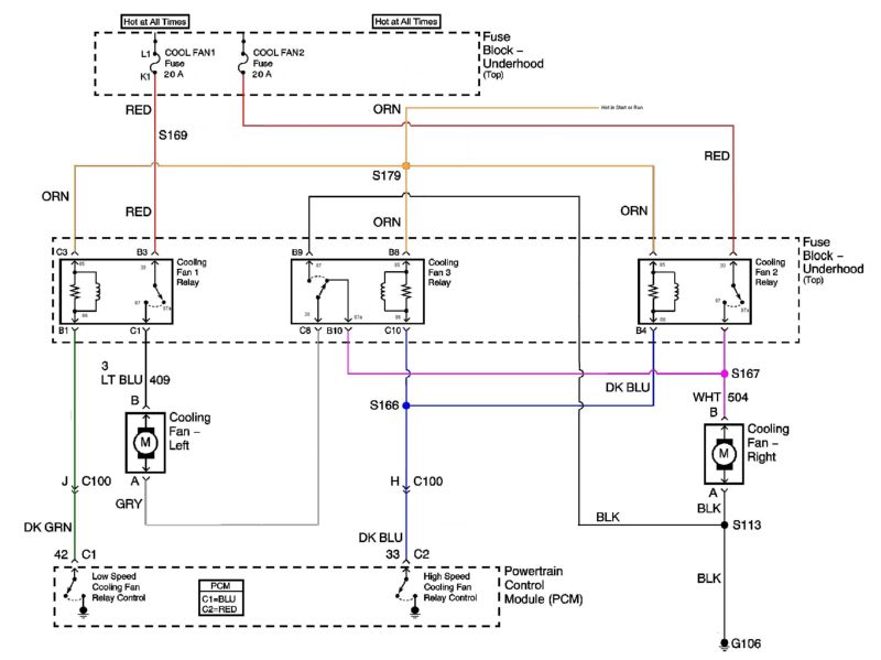
We did ours just like the diagram above, with three relays, hot and switched power with control by the PCM. Works great, and not hard to do. Get standard-size relay sockets that slide together. Use (2) 4-prong relays (R1 and R2), and (1) 5-prong (R3). Arrange them in the sockets just like the diagram.
Note that the low power, control-side pins of the relays are 85-86, which are the ones used by the PCM. Pins 30 and 87 (4-prong) and 30, 87, 87a (5-prong) are used on the power side for the fans. The pin numbering is an SAE standard, and is used world-wide.
Note that the low power, control-side pins of the relays are 85-86, which are the ones used by the PCM. Pins 30 and 87 (4-prong) and 30, 87, 87a (5-prong) are used on the power side for the fans. The pin numbering is an SAE standard, and is used world-wide.
Last edited by Steve VanS; 03-06-2009 at 09:23 AM.
03-06-2009, 11:40 AM
#16
TECH Resident
Thread Starter
SteveVanS,
I've seen the schematics and pin assignments for the relays somewhere; do you have a link to both 4 and 5 pin schematics? Also, I see there's a resistor on the relay coil shown in the Fbody diagram. Do the standard relays include the resistor? I don't see any info on the 4 gang relay (this one): http://haywireinc.com/catalog/produc...a5p00c9oh035s4
to indicate whether it'll accept or is pre-wired for 4 pin or 5 pin relays; is there a way to tell? Where do you get the sockets that slide together?
This is really geat information, and I'm learning a lot. Very much appreciate the feedback and advice!
Andy1
03-06-2009, 12:03 PM
#17
TECH Resident
iTrader: (2)
Join Date: Jun 2006
Location: Roswell, GA
Posts: 802
Likes: 0
Received 0 Likes
on
0 Posts
Pin-by-pin wiring instructions for the relays when using a 99-02 LS1 harness:
http://www.blown.net/cars/camaro68/l...1t56wiring.doc
Here's a pictures of my relays and fuses mounted to my firewall:
http://www.blown.net/cars/camaro68/ac/DSCF6551.html
Not pictured: the fan relay that switches between series and parallel, AC relays
Eventually I'm going to redo my wiring (and that document), combining all of the IGN relays into one bigger relay, and hiding the fuses, relays, and PCM behind the dash.
03-06-2009, 02:15 PM
#18
SteveVanS,
I've seen the schematics and pin assignments for the relays somewhere; do you have a link to both 4 and 5 pin schematics? Also, I see there's a resistor on the relay coil shown in the Fbody diagram. Do the standard relays include the resistor? I don't see any info on the 4 gang relay (this one): http://haywireinc.com/catalog/produc...a5p00c9oh035s4
to indicate whether it'll accept or is pre-wired for 4 pin or 5 pin relays; is there a way to tell? Where do you get the sockets that slide together?
This is really geat information, and I'm learning a lot. Very much appreciate the feedback and advice!
Andy1
I've seen the schematics and pin assignments for the relays somewhere; do you have a link to both 4 and 5 pin schematics? Also, I see there's a resistor on the relay coil shown in the Fbody diagram. Do the standard relays include the resistor? I don't see any info on the 4 gang relay (this one): http://haywireinc.com/catalog/produc...a5p00c9oh035s4
to indicate whether it'll accept or is pre-wired for 4 pin or 5 pin relays; is there a way to tell? Where do you get the sockets that slide together?
This is really geat information, and I'm learning a lot. Very much appreciate the feedback and advice!
Andy1
Relay1 pin 30: hot power
Relay1 pin 87: to LH fan (power)
Relay1 pin 85: switched power
Relay1 pin 86: to PCM by pin J of C100
Relay2 pin 30: hot power
Relay2 pin 87: to RH fan
Relay2 pin 85: switched power
Relay2 pin 86: to PCM by pin H of C100
Relay3 pin 30: to LH fan (or simply ground - no need to splice at S113) ~ this gets to ground thru R3 and RH fan
Relay3 pin 87: to ground
Relay3 pin 87a: to RH fan (power)
Relay3 pin 85: switched power
Relay3 pin 86: to PCM by pin H of C100
So, for example, run a wire from switched power (a run/start source), splice two additional wires to it at S179 in the diagram above, and connect to the 85 terminal of R1, R2 and R3. Then run a jumper from R2-87 to R3-87a .......... and so on.
This word description is the same as the diagram above. Relay1 runs both fans in series at low speed; each fan shares 1 12v source. The PCM energizes R2 and R3 at the same time to run the fans at high speed; each fan then gets its own 12v source.
Last edited by Steve VanS; 03-06-2009 at 02:26 PM.
03-08-2009, 12:15 PM
#19
Teching In

Join Date: Jun 2007
Posts: 48
Likes: 0
Received 0 Likes
on
0 Posts

I'm in the throws of my LS1 wiring and I need some clarification. From online sources Connector 101 pin A:
C101 Plug - grey 10 pin connector
A (remove) YEL/BLK - Low Coolant Sensor
I have the Alldata information on the 2002 and it says that pin A on C101 is yel/blk and it's function is "Starter Enable Relay Control" not Low Coolant Sensor - what is the correct function? For most folks, they don't use the underhood fuse blocks that came with the Camaro and build or buy their own, but I am in my conversion. I have already removed all the unwanted electronics (wires,fuses and relays) about 10lbs worth. But I need this yel/blk wire for my wiring setup as it ties together the clutch pedal start switch and the starter relay. Again, this is the relay in the fuse box NOT the starter relay on the starter. (That big purple wire attaches to this relay in the fuse box). Does anybody have thoughts on this?
Thank you