
Mark VIII fan not coming on
 11-07-2010, 08:24 PM
#1
TECH Resident
Thread Starter
iTrader: (19)
Join Date: Jun 2005
Location: Los Angeles, CA (Burbank)
Posts: 755
Likes: 0
Received 0 Likes
on
0 Posts

Just about ready to drive, getting really close...
For some reason my electric fan isn't coming on when I wire in a fan switch. If I wire one wire from the fan directly to the battery's negative terminal, and the other wire from the fan directly to the battery's positive terminal, the fan turns on.
When I wire the fan switch, fan doesn't do anything. I know I need to use a relay. I'm stripping everything out to see if I have a faulty fan switch.
Here's how I've wired it:

I put a lighter underneath but away from the probe. The fan should come on under something that hot, correct??
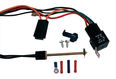
I'm using a Derale switch, a probe style, part number 16738:
I've never done this before so I don't know if I'm missing something. To me it sounds like I have a faulty switch.
Anyone have any advice/suggestions on what I should do next? Thanks again guys
For some reason my electric fan isn't coming on when I wire in a fan switch. If I wire one wire from the fan directly to the battery's negative terminal, and the other wire from the fan directly to the battery's positive terminal, the fan turns on.
When I wire the fan switch, fan doesn't do anything. I know I need to use a relay. I'm stripping everything out to see if I have a faulty fan switch.
Here's how I've wired it:
I put a lighter underneath but away from the probe. The fan should come on under something that hot, correct??
I'm using a Derale switch, a probe style, part number 16738:
I've never done this before so I don't know if I'm missing something. To me it sounds like I have a faulty switch.
Anyone have any advice/suggestions on what I should do next? Thanks again guys
 11-07-2010, 08:44 PM
#2
TECH Resident
iTrader: (55)
Join Date: Oct 2005
Location: Cleveland, Oh
Posts: 847
Likes: 0
Received 0 Likes
on
0 Posts
maybe you're not getting it hot enough. remember the probe itself needs to get 180+ to trigger. I'd suggest getting the flame closer or a hotter substance like boiled water in a glass
11-08-2010, 12:13 AM
#3
TECH Resident
Thread Starter
iTrader: (19)
Join Date: Jun 2005
Location: Los Angeles, CA (Burbank)
Posts: 755
Likes: 0
Received 0 Likes
on
0 Posts
I'm thinkin about getting another probe to find out if that's what it is.
11-08-2010, 08:50 AM
#4
TECH Enthusiast

Those fans will not work with a 40 amp relay you need a 60. I tried to hook on up with a factory harness and it blew the 40 amp fuses like they were nothing. Those are great fans and they outflow any aftermarket fan out there.
11-08-2010, 08:59 AM
#5
TECH Resident
Thread Starter
iTrader: (19)
Join Date: Jun 2005
Location: Los Angeles, CA (Burbank)
Posts: 755
Likes: 0
Received 0 Likes
on
0 Posts
Right now though I'm just trying to get the fan to turn on with some heat on the probe switch! So I took the relay out of the equation. Still not working. I'm thinking I should get another one and see if that's the problem.
When I use a jumper cable at the ends of the switch (basically completing the circuit), the fan turns on, so that makes me feel like I've got a bad switch.
I've never wired one of these before though so I wanted to get a second opinion. Or third. Or fourth... haha
11-08-2010, 10:17 AM
#6
That switch isn't rated to carry that much current. It probably won't stand being heated up with a lighter either. It might have quit working when you tried to test it.
Use a test lamp or ohm meter and a pot of boiling water to check the new switch that you buy.
Bythe way, try and grab the relays from the donor vehicle. New 60 amp relays are pretty pricey.
Use a test lamp or ohm meter and a pot of boiling water to check the new switch that you buy.
Bythe way, try and grab the relays from the donor vehicle. New 60 amp relays are pretty pricey.
Trending Topics
11-08-2010, 11:20 AM
#8
On The Tree
iTrader: (3)
Join Date: Feb 2008
Location: Rochester, Ny
Posts: 137
Likes: 0
Received 0 Likes
on
0 Posts
I bought my fan relay set up from The Hollister Road Company and it works pretty damn good.
http://www.hollisterroad.com/proddet...?prod=MarkVIII
http://www.hollisterroad.com/proddet...?prod=MarkVIII
11-08-2010, 11:56 AM
#9
TECH Resident
Thread Starter
iTrader: (19)
Join Date: Jun 2005
Location: Los Angeles, CA (Burbank)
Posts: 755
Likes: 0
Received 0 Likes
on
0 Posts
I then removed the relay and ran a cheapo flip switch in between the ground circuit. When it was off, the fan was off. When it was on, the fan was on.
So I replaced that switch with the probe switch and put the probe end in boiling water. The fan did not turn on.
I understand that switch is not meant for that much current. I was merely trying to make a simple circuit to narrow down why this wasn't working. For a few seconds of current, I don't think the probe switch would burn out. For an extended period of time, sure.

 11-08-2010, 12:48 PM
#13
TECH Enthusiast
Try an older fan switch setup like the Gran Nationals. I believe most guys use those because they are 180 degrees unless you want something higher. All you need to do is put the relay to the ground on those. Otherwise the 3rd gen F-bodies are another good choice for the fan switch.
11-08-2010, 01:11 PM
#14
TECH Resident
Thread Starter
iTrader: (19)
Join Date: Jun 2005
Location: Los Angeles, CA (Burbank)
Posts: 755
Likes: 0
Received 0 Likes
on
0 Posts
Thanks for all the responses guys. I ordered a new temp switch and a 70 amp relay. I'll post back my results when they get here.
11-08-2010, 01:12 PM
#15

EDIT I just noticed the wiring in the picture is wrong. In short the way to fix your problem is one of the wires from the thermoswitch should be going to the relay, the other wire out of the thermoswitch should be going to a ground source, the fan should have its own ground wire to the battery or frame.
in more detail, the thermoswitch is a ground trigger for the relay, so one wire out of the thermoswitch goes to a ground source and the other wire out of the thermoswitch goes to the relay to trigger it. The fan should have its own dedicated ground, like a wire off the fan ground to the battery or to the frame, the relay setup should only be operating the hot wire if its a basic thermoswitch and relay setup.
You should have a hot wire to the battery that is large and goes to the 30 pin, then 87 should go to the fan + pin and also be a large wire, these are the wires that carry the amperage. You will then have your trigger wires that are small, you will have a hot wire going into the relay that is constant or a ground that is constant. Whichever one is not constant the other is switched and that is what activates the realay and turns the fan on, so if you have a small red wire to the battery out of the relay and a small black wire to the thermoswitch then the thermoswitch is your relay trigger since the small red goes directly to the battery, and means it is constant, not switched. I saw there were two black wires coming out of the thermoswitch so I assume this is the deal, run one wire to the ground on the battery or to the radiator support, the other black wire should already be going into the relay.
Then run a dedicated ground for your fan - wire to the battery or radiator support/frame. If the thermoswitch is you negative trigger then the a/c wire will also be a negative trigger. Most of the setups I have used were adjustable and worked a little different than this. They used positive relay triggers. Anyway try that and report!!!
If you want to test your thermoswitch and you know with no doubt what so ever that everything is wired correctly, then tap into the wire from the thermoswitch where it goes into the relay, since this is the wire that triggers the relay, and touch that to a ground if the fan runs that means the relay is good but you are not getting a trigger to the relay which will show you the thermoswitch is bad.
A 40 AMP is generally good enough for a single fan, most electric fans pull 15-20 amps. If a fan is blowing 40 amp fuses as someone else stated above its either a really really big fan or it is on its way out, I seen many blown radiator fan fuses in bone stock applications because the fan motors were wearing out causing higher amperage draw. They would blow the stock 30 amp fuse because they were pulling more amperage than that, when I would put in a new electric motor or entire assembly my average amp draw reading would be right at 15, I saw this with aftermarket fan assemblies as well
11-08-2010, 01:16 PM
#16
FYI The only way a 70 amp relay will do you any good is if you have the relay socket and wiring that is also rated to carry that many amps to go with it, wiring will get hot and burn up if you run too much amperage through it. The 30-40 amp you have should be just fine.
11-08-2010, 02:55 PM
#17
Sounds like you are doing it right. Must be a bad part.
I am running an adjustable derale controller to trigger the low speed setting of a Taurus fan. My car doesn't need the high speed. I use the relay on the derale set up to trigger the stock relay I pulled from the Taurus.
I have read that the Mark VIII fans are more efficient and don't have the current draw the Taurus fans do. You may not need a 70 amp relay, but it can't hurt either. On high speed the Taurus fans do draw some mondo current.
11-08-2010, 02:57 PM
#18
TECH Resident
Thread Starter
iTrader: (19)
Join Date: Jun 2005
Location: Los Angeles, CA (Burbank)
Posts: 755
Likes: 0
Received 0 Likes
on
0 Posts
That would make sense, and also seems like the way they've wired it in the instructions here: http://static.summitracing.com/globa.../der-16738.pdf Please look at page 2, it will have the relay wiring diagram and it sounds very similar to the way you're describing, pooter.
HOWEVER, man i thought a switch is just a switch. It closes and opens a circuit. So in a simple circuit, a switch on the ground side wouldn't act any different than the switch on a power side, as far as completing the circuit to the load. Right?? Am I missing something here?
11-08-2010, 03:18 PM
#19
Ok, thanks!! Now when you say "one of the wires from the thermoswitch should be going to the relay" THAT wire should be going to power, if the "other wire out of the thermoswitch should be going to a ground source." Is that correct???
That would make sense, and also seems like the way they've wired it in the instructions here: http://static.summitracing.com/globa.../der-16738.pdf Please look at page 2, it will have the relay wiring diagram and it sounds very similar to the way you're describing, pooter.
HOWEVER, man i thought a switch is just a switch. It closes and opens a circuit. So in a simple circuit, a switch on the ground side wouldn't act any different than the switch on a power side, as far as completing the circuit to the load. Right?? Am I missing something here?
On your second question, you are correct, a switch is a switch. Now start looking at your thermoswitch as just a switch "switched" by temperature, the relay has everything it needs except the trigger to activate it, thats where the thermoswitch comes in. Wire it all up as I have written below, turn the car on, and without even starting it you can touch the green wire to a positive wire and the fan will run, same thing happens once the thermoswitch is wired properly and it gets to temperature, it lets positive power go through and activates the relay. Both the green wire and the Brown wire are on the exact same terminal, which ever one sends positive power will activate the relay.
On to wiring, I now see how they are doing it, they are using a hot trigger. Run Pin 30/Red wire to the battery +. Run Pin 87/Blue or Orange wire to the positive terminal on the fan. Run a dedicated ground wire from the fan negative terminal to a ground. Run pin 86/Black wire to a ground. Pin 85/Green wire goes to the positive wire on your A/C compressor to manually trigger the fan when the A/C is turned on.
NOW ON you thermostatic switch, it is a positive trigger, once a certain temp is reached the thermostatic switch will close internally completing a circuit that runs positive power THROUGH it and back out to the relay, triggering it, and running the fan, which is the same thing as if you put positive power to the green wire. Your 86 Pin or black wire could be a trigger but it is ran directly to ground so it is not, the 85 Pin Brown and Green wires are your trigger, and they are ran to positive sources. So run the yellow wire out of the thermostatic switch to a wire that becomes hot/positive when the key is turned on, that way the fan will only run if the key is on, not when the car has been shut off.
A relay just opens and closes a circuit, and a switch is just a switch yes, and all it does is open and close a circuit, a relay is just a switch that is able to be controlled by inputs. The thermostatic switch is a switched input to the relay that once the 86/Black wire (ground) and the 85/Green or Brown (positive) wire become energized it activates and electromagnet in the relay that closes the circuit between pins 87 and 30, so basically is just a switch for pins 87 and 30. Then power is allowed to flow through those two pins and the fan runs. And your brown wire gets the positive signal by way of a positive wire being ran into the yellow wire and then once it hits "said" temperature it closes and sends the power on through to the brown wire.
Last edited by 00pooterSS; 11-08-2010 at 03:27 PM.
11-08-2010, 03:39 PM
#20
TECH Resident
Thread Starter
iTrader: (19)
Join Date: Jun 2005
Location: Los Angeles, CA (Burbank)
Posts: 755
Likes: 0
Received 0 Likes
on
0 Posts
Read through your post, everything makes sense!! When I get home I will wire it like that, just to make sure. I'm 99% positive I wired it correctly through the relay the first time, but maybe I missed something.
I'll try it again wired correctly, and then I'll put the probe in some boiling water and see if that ****** turns on.
I'll try it again wired correctly, and then I'll put the probe in some boiling water and see if that ****** turns on.