
71 Pontiac Lemans

 10-21-2012, 11:01 AM
#42
Staging Lane
Thread Starter

Next step was to put the body back on the frame.
I just reversed the procedure when I removed the body - we rolled the rolltisserie back to horizontal and supported the body again with the concrete blocks and 2x4s as before. At this point the rolltisserie was removed from the body. The frame was rolled back under the body and I lowed the body back onto the frame, doing it gradually removing a 2x4 spacer at each corner at a time so the body wouldn't get twisted. As I got closer I lined up the frame under the body so the body bolt holes would line up.
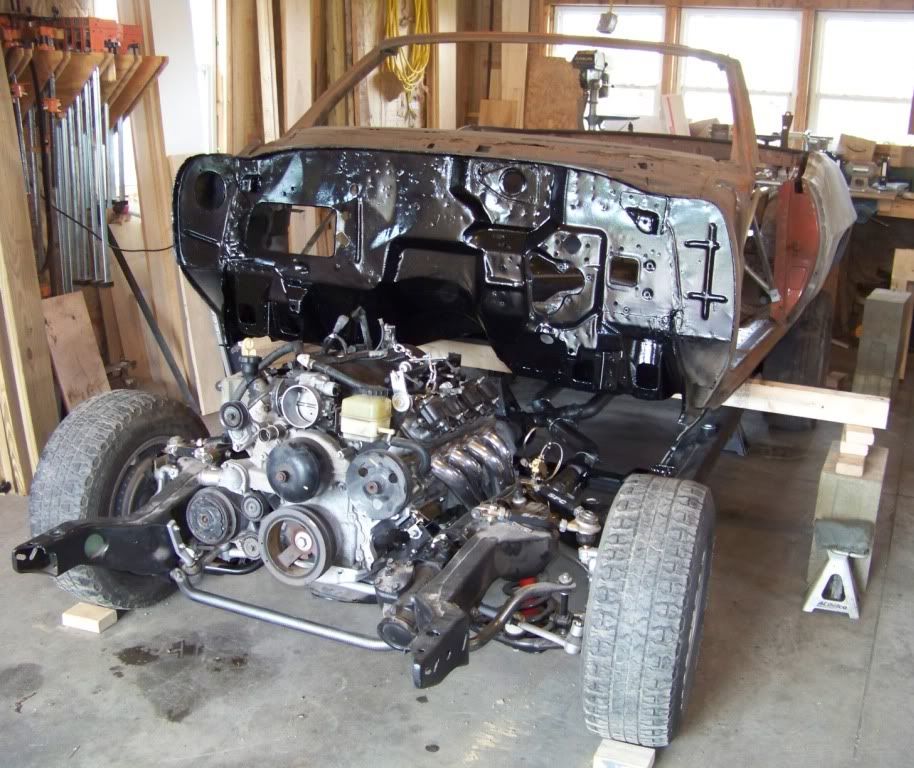
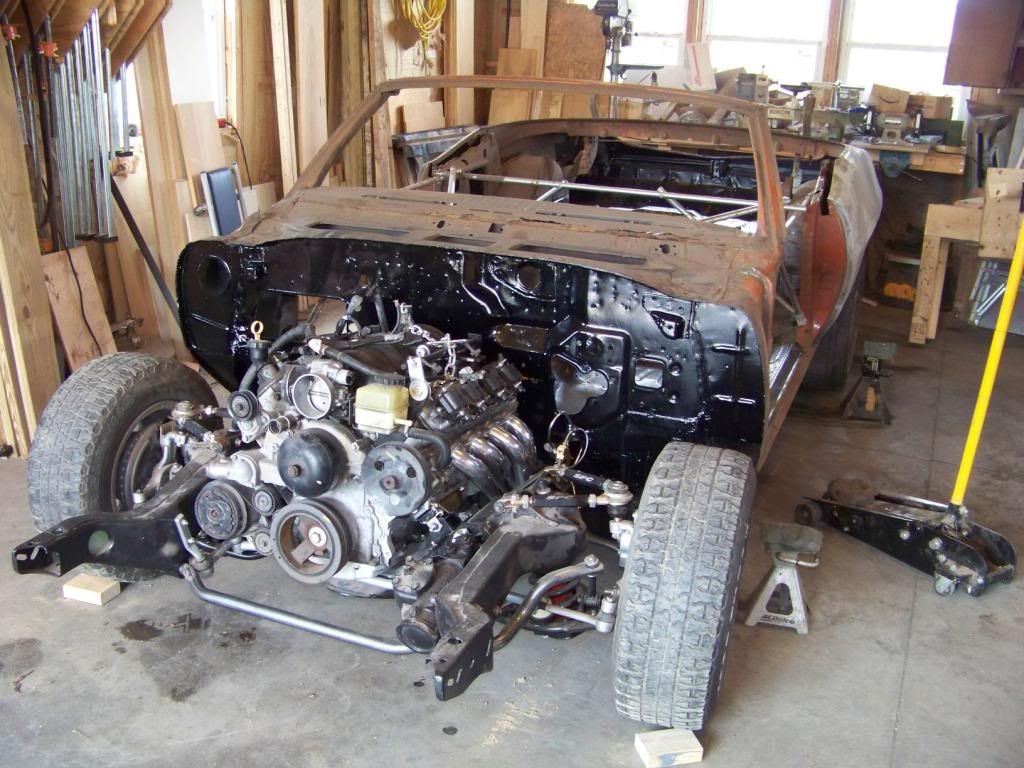
When I removed the body from the frame most of the cage nuts were rusted to the point where they either broke or I had to cut through the bolt. I don't particular care for this GM design where the nuts were hidden in body cavities the way they were, if the body were ever to be removed again I wanted the process to be easier. I also wanted to use stainless fasteners as much as possible and cage nuts don't come in stainless. Here is what I came up with.
In most locations I drilled 1 1/2" holes through the sheet metal floor directly above the bolt locations. I did this by first drilling a small pilot hole through the sheet metal floor from the bottom through the larger body hole in the floor brace while the body was rotated on the rolltisserie. I then drilled the 1 1/2" hole from the top through the floor using a bi-metal hole saw. I bought 7/16" stainless bolts of varying lengths along with stainless nylon lock nuts and large stainless fender washers. I also used new rubber body mount bushings I bought from OPGI, and used the cone washers that came with the kit but not the bolts.
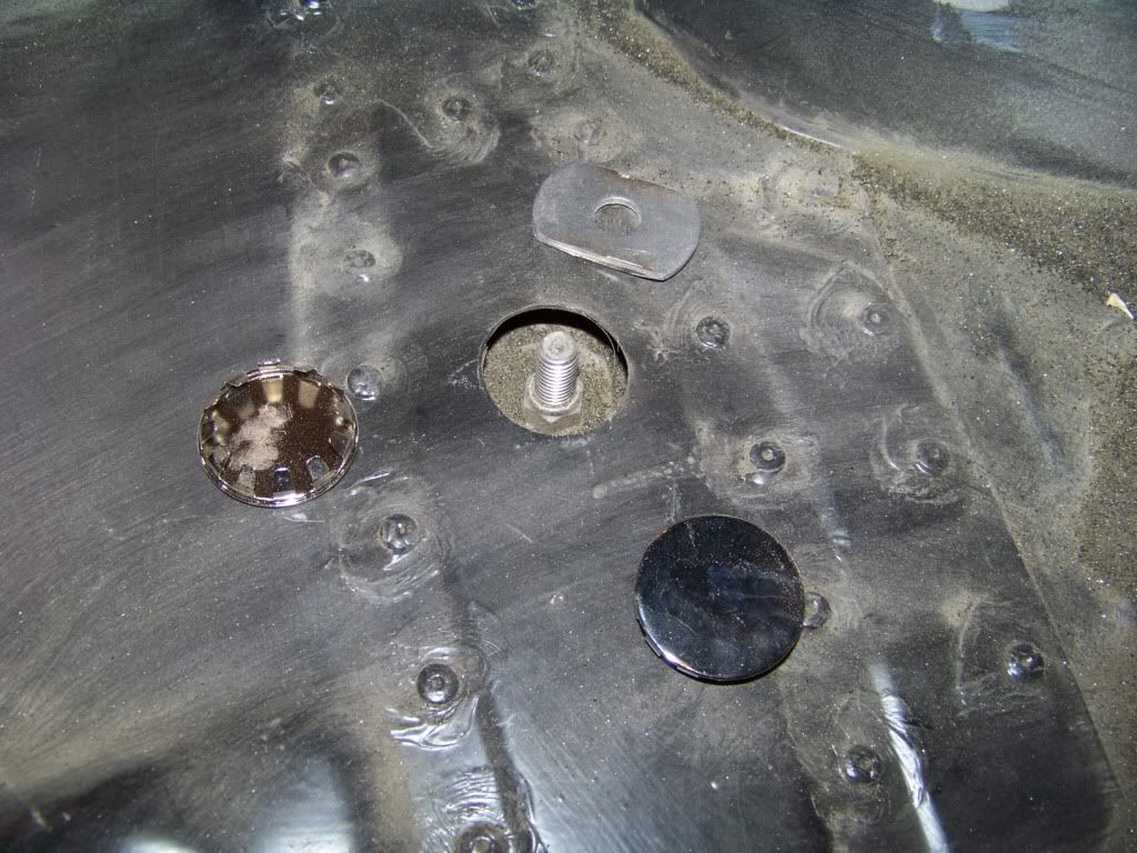
I had to trim the upper washer as shown so it would fit through the 1 1/2" hole in the floor. I was able to reach all of the bolts and nuts to tighten them by myself except the ones under the trunk hinges, those need two people to do. The hole in the floor will be covered up with the 1 1/2" diameter chrome cap, which is a standard item in the blue hardware drawers at Lowes. I will just run the Dynamat over these covers.
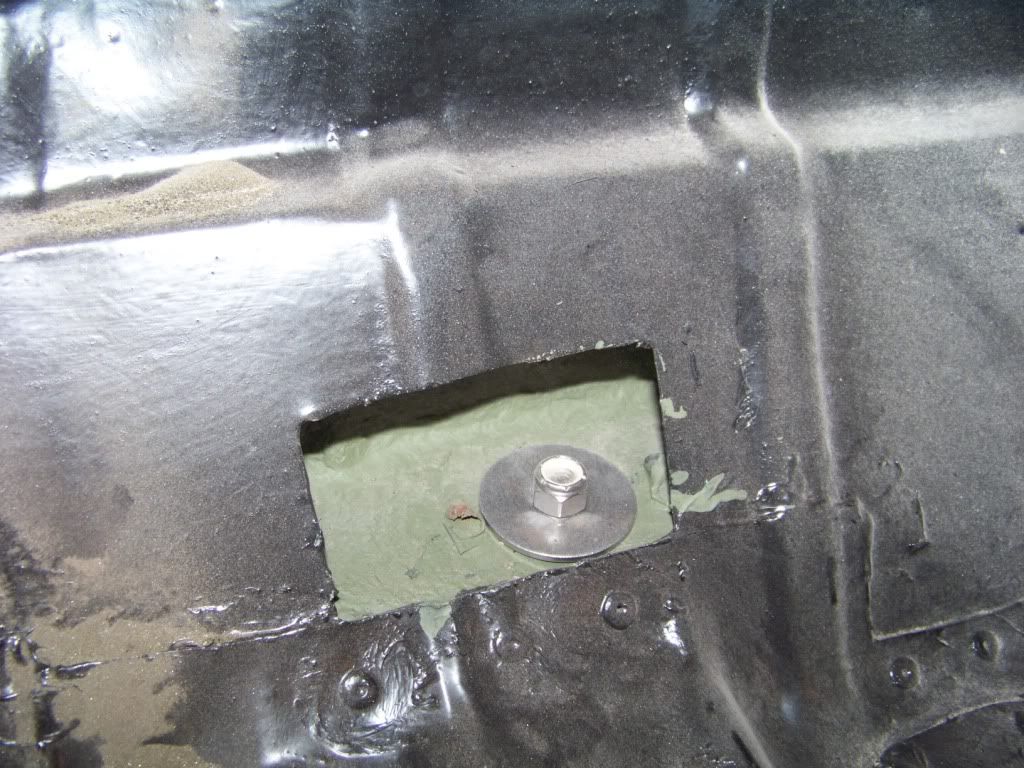
The most rear mounts were a little different situation due to where they were located. I cut a square hole in the area in the trunk to access the cavity to install the washer and nut. I will make a overlapping cover panel which will be painted and installed with stainless screws and sealant. Cutting these holes also allowed access to spray the cavity with internal frame coating.
I just reversed the procedure when I removed the body - we rolled the rolltisserie back to horizontal and supported the body again with the concrete blocks and 2x4s as before. At this point the rolltisserie was removed from the body. The frame was rolled back under the body and I lowed the body back onto the frame, doing it gradually removing a 2x4 spacer at each corner at a time so the body wouldn't get twisted. As I got closer I lined up the frame under the body so the body bolt holes would line up.
When I removed the body from the frame most of the cage nuts were rusted to the point where they either broke or I had to cut through the bolt. I don't particular care for this GM design where the nuts were hidden in body cavities the way they were, if the body were ever to be removed again I wanted the process to be easier. I also wanted to use stainless fasteners as much as possible and cage nuts don't come in stainless. Here is what I came up with.
In most locations I drilled 1 1/2" holes through the sheet metal floor directly above the bolt locations. I did this by first drilling a small pilot hole through the sheet metal floor from the bottom through the larger body hole in the floor brace while the body was rotated on the rolltisserie. I then drilled the 1 1/2" hole from the top through the floor using a bi-metal hole saw. I bought 7/16" stainless bolts of varying lengths along with stainless nylon lock nuts and large stainless fender washers. I also used new rubber body mount bushings I bought from OPGI, and used the cone washers that came with the kit but not the bolts.
I had to trim the upper washer as shown so it would fit through the 1 1/2" hole in the floor. I was able to reach all of the bolts and nuts to tighten them by myself except the ones under the trunk hinges, those need two people to do. The hole in the floor will be covered up with the 1 1/2" diameter chrome cap, which is a standard item in the blue hardware drawers at Lowes. I will just run the Dynamat over these covers.
The most rear mounts were a little different situation due to where they were located. I cut a square hole in the area in the trunk to access the cavity to install the washer and nut. I will make a overlapping cover panel which will be painted and installed with stainless screws and sealant. Cutting these holes also allowed access to spray the cavity with internal frame coating.
10-22-2012, 06:28 AM
#43
TECH Fanatic
Looks good, I used a similar method in a couple of past projects. It really makes reassembly much easier. When I jack the body off the 69 I am not even going to try to remove some of the bolts, just start cutting access holes on top first, save the grief.
10-23-2012, 09:46 AM
#44
Staging Lane
Thread Starter
Thanks for all the comments, it is appreciated.
I don't know what I am doing for wheels yet, that's obviously a ways down the road so to speak. I do like the Boss 338s with the grey centers, 18x8 for the fronts and 18x10 for the rear.
Once the body was back on the frame I was eager to get the engine started as most of you would. So that meant I needed to get a lot of things installed in the engine bay.
I noticed on the new GTO a lot of components were mounted on the inner fenders. I wanted to move things over as simply as possible so I figured I would reinstall these components in similar locations on the Lemans. I didn't want to rework the harness and possibly create a lot of headaches so that's why I was compelled to use the existing component locations as much as possible. I had previously blasted, primed and painted the inner fenders in preparation for this time so I went ahead and installed them. I also installed the radiator core support and passenger fender to help support it. I am going for a factory look here, as if GM would have built a 71 Lemans with 2004 technology.
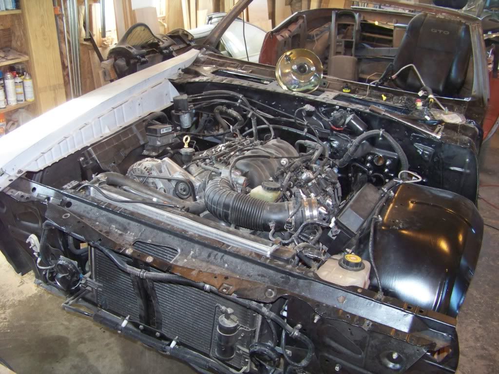
On the new GTO the underhood fuse panel and cruise/throttle cable components are mounted on the passenger inner fender. These pictures shows how I mounted these. I made brackets as required and attached everything through existing or new holes in the inner fender with stainless bolts. When placing components I kept in mind that the associated connectors on the wiring harness had to reach the components so I laid the wiring harness over the engine bay as I did this process.
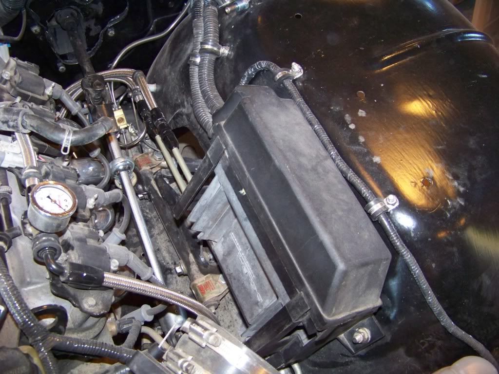
This picture shows the mounting of the underhood fuse panel.
The fuse panel attaches directly to the inner fender on the back side, the forward side needed a bracket I made to support it:
This picture shows the mounting of the cruise and throttle cable components.
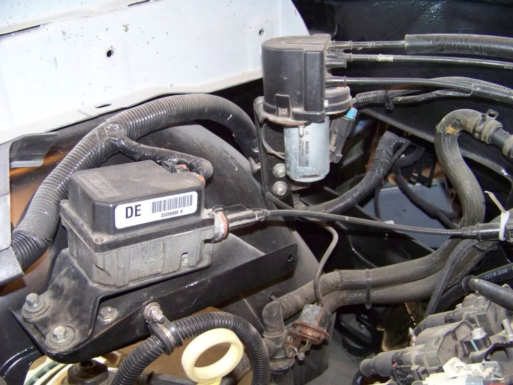
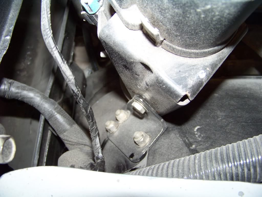
I am not sure exactly what these components are, I assume the forward box shaped item is the cruise servo, the rear cylindrical thing is where all the cruise and throttle cables come together. For the cruise servo I cut the supporting bracket from the GTO donor and mounted it with a supporting bracket underneath that I made.
For the cable component I made a bracket from some angle to support it on the inner fender, this is a view looking down, forward is to the right:
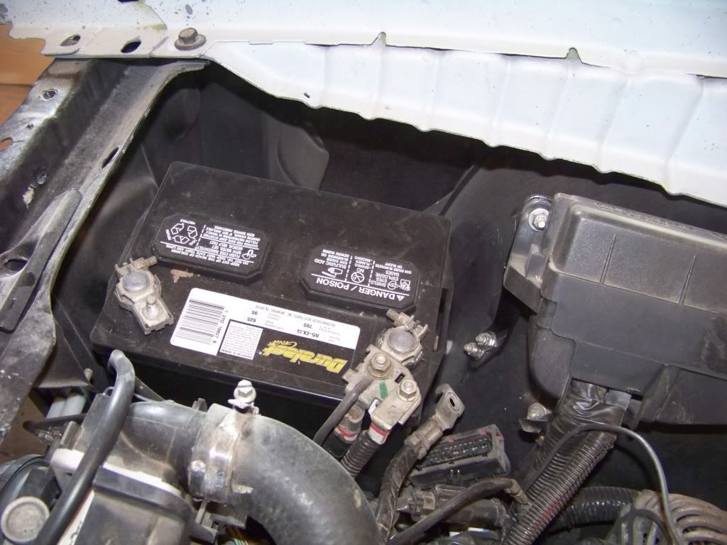
On the new GTO the battery is located on the passenger side just behind the headlight. I was at a car show a few months ago and noticed on Pontiac A-bodies the battery is on the driver�s side and on Chevelles the battery is on the passenger side. To keep things the same as the new GTO I mounted the battery on the Chevelle or passenger side. Since my GTO donor didn�t come with a battery I got a new one from Autozone. I got the correct battery for the new GTO, it fits in the a-body location just fine.
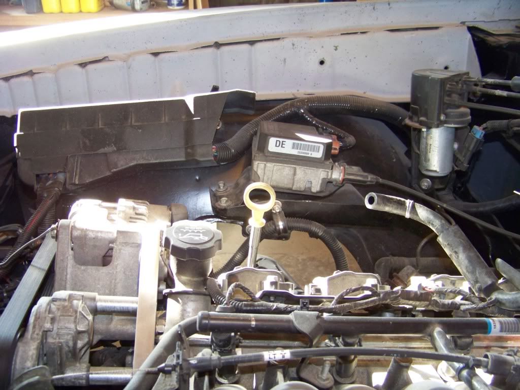
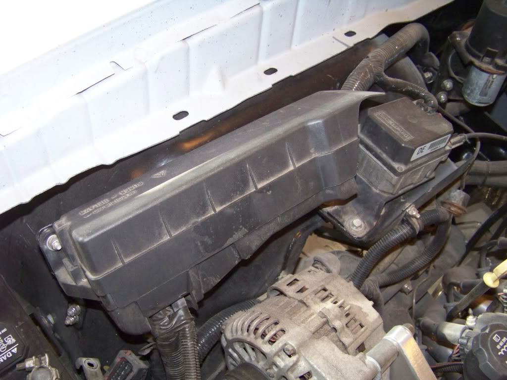
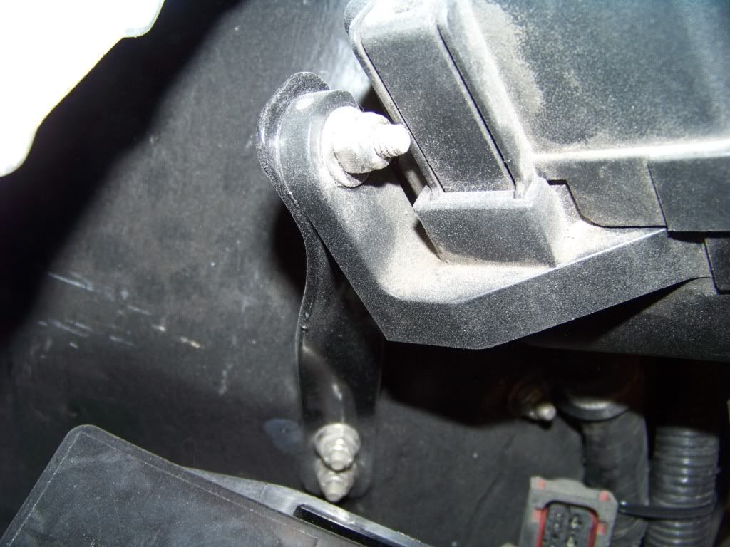
On the new GTO the ECM is mounted on the lower driver�s inner fender just above the frame rail. Again, I picked a similar location although I moved it up to get it away from the header. The ECM is mounted in a plastic holder with a cover. I just used the holes in the holder to locate new holes in the inner fender.
I don't know what I am doing for wheels yet, that's obviously a ways down the road so to speak. I do like the Boss 338s with the grey centers, 18x8 for the fronts and 18x10 for the rear.
Once the body was back on the frame I was eager to get the engine started as most of you would. So that meant I needed to get a lot of things installed in the engine bay.
I noticed on the new GTO a lot of components were mounted on the inner fenders. I wanted to move things over as simply as possible so I figured I would reinstall these components in similar locations on the Lemans. I didn't want to rework the harness and possibly create a lot of headaches so that's why I was compelled to use the existing component locations as much as possible. I had previously blasted, primed and painted the inner fenders in preparation for this time so I went ahead and installed them. I also installed the radiator core support and passenger fender to help support it. I am going for a factory look here, as if GM would have built a 71 Lemans with 2004 technology.
On the new GTO the underhood fuse panel and cruise/throttle cable components are mounted on the passenger inner fender. These pictures shows how I mounted these. I made brackets as required and attached everything through existing or new holes in the inner fender with stainless bolts. When placing components I kept in mind that the associated connectors on the wiring harness had to reach the components so I laid the wiring harness over the engine bay as I did this process.
This picture shows the mounting of the underhood fuse panel.
The fuse panel attaches directly to the inner fender on the back side, the forward side needed a bracket I made to support it:
This picture shows the mounting of the cruise and throttle cable components.
I am not sure exactly what these components are, I assume the forward box shaped item is the cruise servo, the rear cylindrical thing is where all the cruise and throttle cables come together. For the cruise servo I cut the supporting bracket from the GTO donor and mounted it with a supporting bracket underneath that I made.
For the cable component I made a bracket from some angle to support it on the inner fender, this is a view looking down, forward is to the right:
On the new GTO the battery is located on the passenger side just behind the headlight. I was at a car show a few months ago and noticed on Pontiac A-bodies the battery is on the driver�s side and on Chevelles the battery is on the passenger side. To keep things the same as the new GTO I mounted the battery on the Chevelle or passenger side. Since my GTO donor didn�t come with a battery I got a new one from Autozone. I got the correct battery for the new GTO, it fits in the a-body location just fine.
On the new GTO the ECM is mounted on the lower driver�s inner fender just above the frame rail. Again, I picked a similar location although I moved it up to get it away from the header. The ECM is mounted in a plastic holder with a cover. I just used the holes in the holder to locate new holes in the inner fender.
10-24-2012, 06:27 AM
#45
TECH Fanatic
I was after a similar flavor with mine. I have had a few guys scratching their heads when I pop the hood as they try to decide what they are looking at. I was able to sort of hide the PCM and intercooler pump under the fluid tank on the driver side where the battery was to start. I also moved the battery to the PS. Which battery tray did you use. I tried a Chevelle that did not work, ended up cutting and pasting to make one fit.
10-25-2012, 04:45 PM
#46
Staging Lane
Thread Starter
oldgoat69: I had bought the Pontiac tray several months ago so I modified and used that. I thought about getting the Chevelle tray, but based on your experience I am glad I didn't. I cut the existing tabs off and welded new ones on as required to get it to fit in the passenger location.
10-25-2012, 06:50 PM
#47
Staging Lane
Thread Starter
Alternator Relocation
As I mentioned in a previous post I decided to relocate the alternator after I discovered it would interfere with the steering gearbox. I looked into the different kits on the market to accomplish the task but didn�t want to spend the money. These kits start at about $150 and go into several hundreds for the fancy kits with polished parts and such. For this project I am more interested in function than form so I set about making my own mount.
I decided to relocate the alternator up high on the passenger side. This brings it up closer to the battery and underhood fuse panel. I think it would have been tougher to put it high on the driver�s side with the existing power steering pump.
I was inspired by the solution that Rockytopper came up with in his 65 Olds. He no longer makes these but I came up with a similar design after studying his pictures and taking measurements.
The alternator was originally mounted on the front of the block down low on the driver�s side. It appeared to me that the front of the driver�s side head was on the same plane as the front of the block, and I researched and found out that the passenger side head is offset to the rear about 0.75 inch. So I decided to base my bracket on a 0.75 think aluminum plate figuring that would put the alternator roughly in the same plane again. I went through several designs using �� particle board until I had a design I was happy with. I actually spent more time fussing with the tensioner relocation trying to get the proper leverage to tension the belt. This bracket relocates both items.
Below is a drawing with dimensions of my bracket. I made it from a 8 inch by 8 inch by 0.75 inch aluminum plate that I bought from McMaster for about $39 (part number 9246K51). At the time I didn�t have access to a machine shop so I cut this plate with a reciprocating saw and finished it with belt and spindle sanders. Crude, but I got it done.
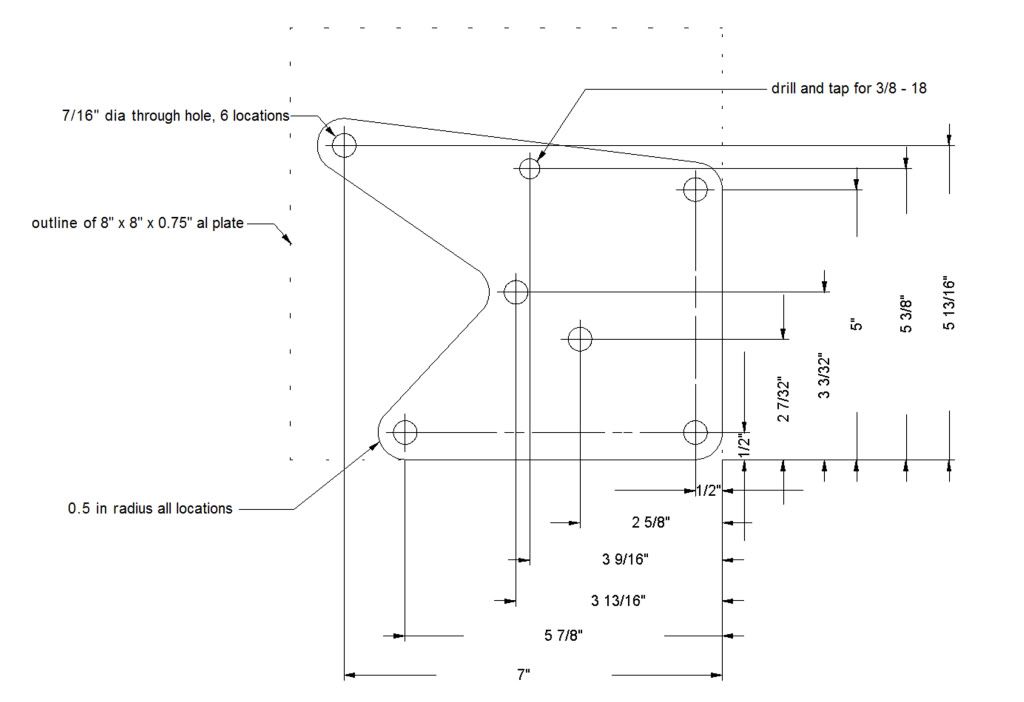
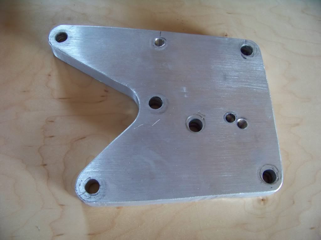
Disregard the two holes right next to each other, they were from an earlier unsuccessful attempt to relocate the tensioner bracket.
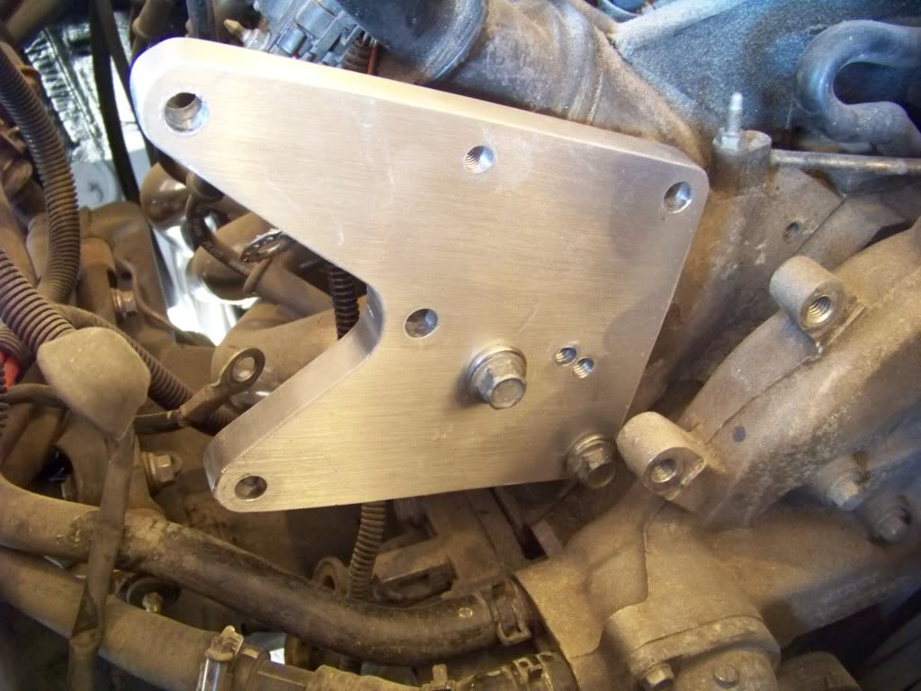
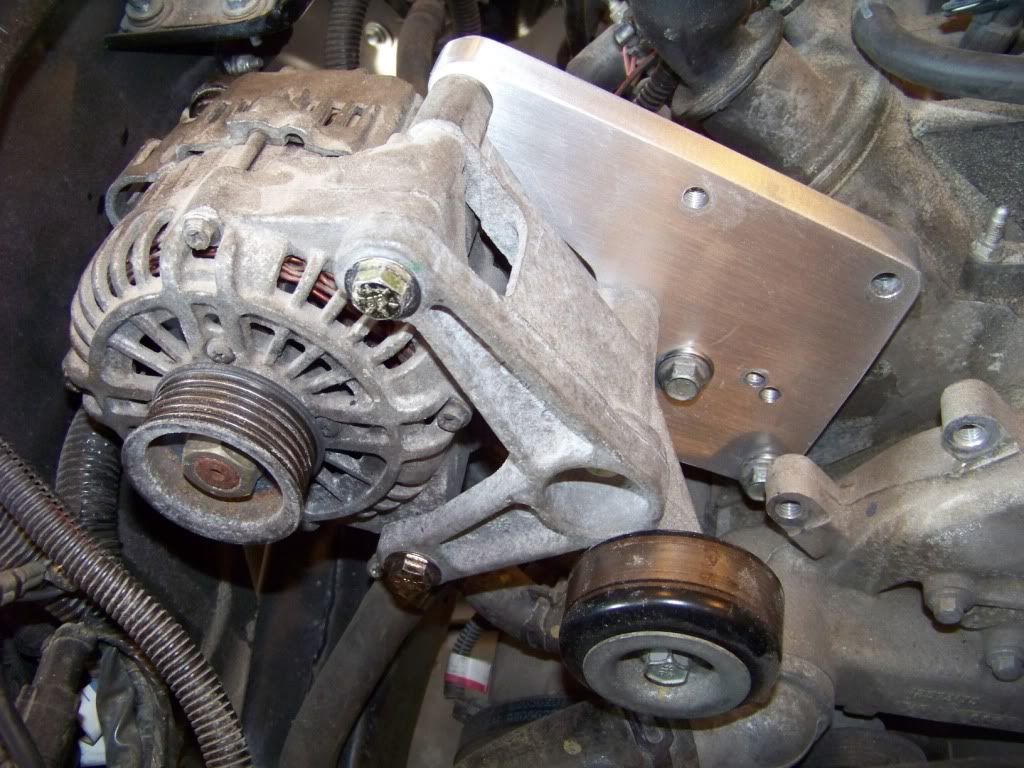
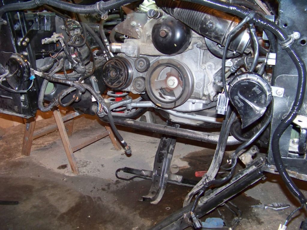
The picture below shows where I mounted the bracket. I am using the three outer holes on the front of the passenger head. The fourth most inner hole is not used. In this picture you can also see the two holes just below on the water pump that used to support the tensioner bracket.
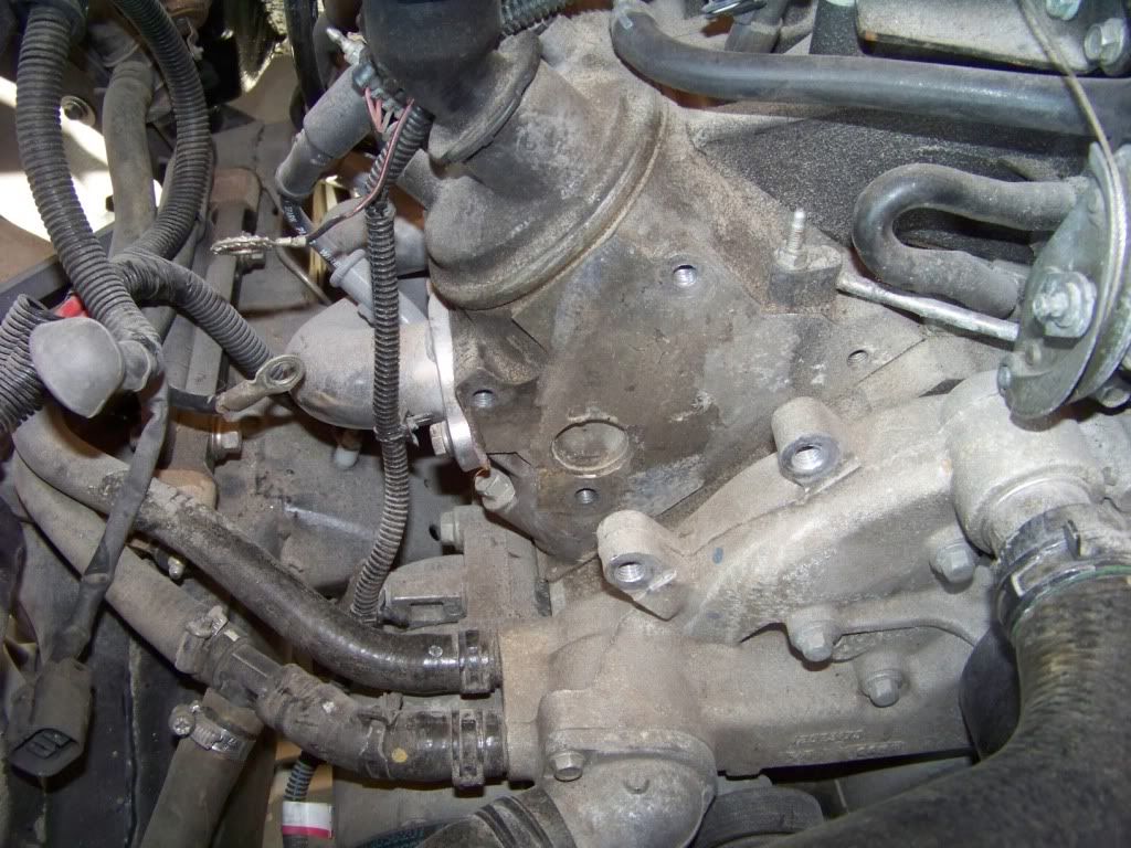
The bracket is mounted to the front of the passenger side head with M10-1.5 x 40 bolts as shown below. The holes in the head are already tapped to that thread size.
The alternator is mounted to the bracket with two 3/8 x 5 1/2 in. bolts and one 3/8 x 4 1/2 bolt, I used grade 8 bolts.
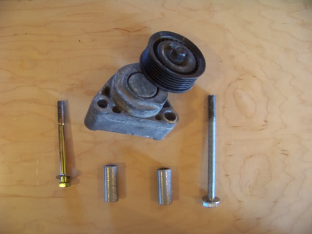
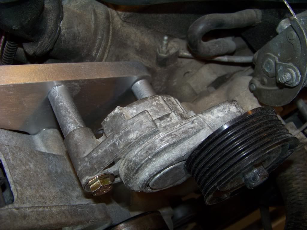
The tensioner is mounted with one M10-1.5 x 130 bolt in the inner hole, this bolt goes through the hole on the alternator bracket and into the existing hole in the head. The outer bolt is 3/8 x 4 and threads into the alternator bracket. To keep the tensioner aligned with the other pulleys it is installed with spacers between the alternator bracket and the tensioner bracket. These spacers, made from 1/2" pipe or heavy conduit, are 1.70 inches long.
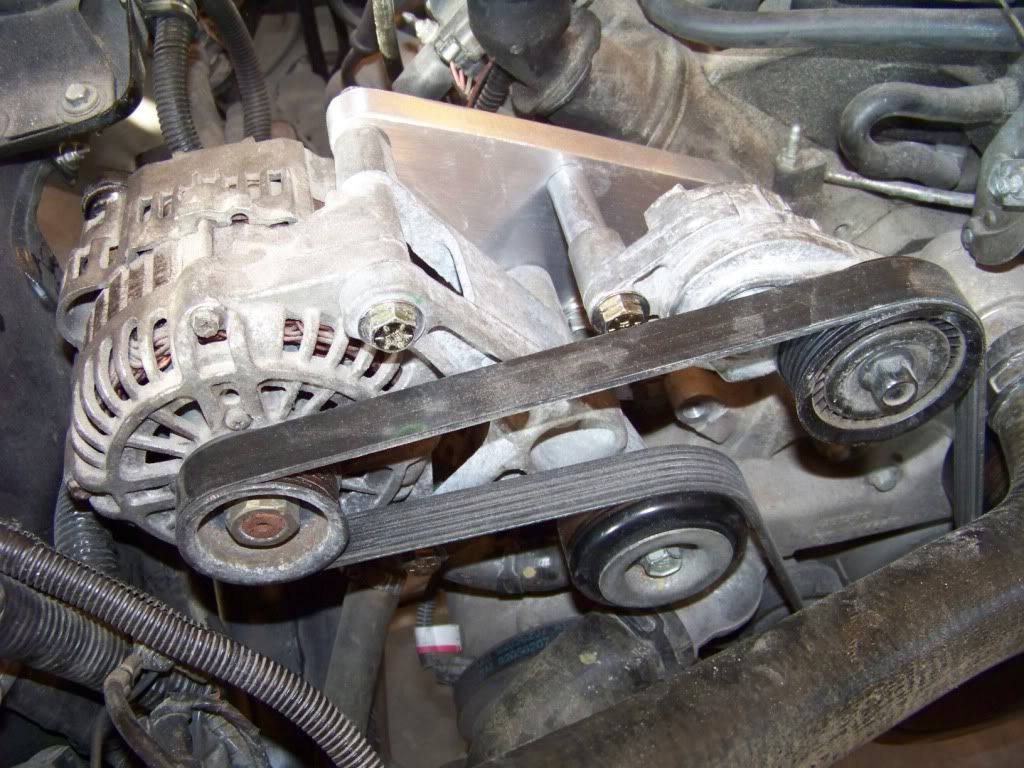
I put a straightedge across some of the pulleys to make sure they were in the same plane, I did put one washer between the alternator and bracket at each of the three bolt locations to get the pulleys in the same plane.
For the belt length I tried measuring with a string and then a metal tape measure wrapped around all of the pulleys but that only got me a starting point for belt length. From there it was a trial and error process of getting belts from the auto parts store and trying different ones until one worked well. For this particular installation that ended up being a Gates K060815 belt (six ribs, 81.5 inches long). This belt fits pretty snug, the tensioner is at the higher end of its scale.
The bracket seems very sturdy and I have run the engine several times without issue, although not at full throttle yet.
As I mentioned in a previous post I decided to relocate the alternator after I discovered it would interfere with the steering gearbox. I looked into the different kits on the market to accomplish the task but didn�t want to spend the money. These kits start at about $150 and go into several hundreds for the fancy kits with polished parts and such. For this project I am more interested in function than form so I set about making my own mount.
I decided to relocate the alternator up high on the passenger side. This brings it up closer to the battery and underhood fuse panel. I think it would have been tougher to put it high on the driver�s side with the existing power steering pump.
I was inspired by the solution that Rockytopper came up with in his 65 Olds. He no longer makes these but I came up with a similar design after studying his pictures and taking measurements.
The alternator was originally mounted on the front of the block down low on the driver�s side. It appeared to me that the front of the driver�s side head was on the same plane as the front of the block, and I researched and found out that the passenger side head is offset to the rear about 0.75 inch. So I decided to base my bracket on a 0.75 think aluminum plate figuring that would put the alternator roughly in the same plane again. I went through several designs using �� particle board until I had a design I was happy with. I actually spent more time fussing with the tensioner relocation trying to get the proper leverage to tension the belt. This bracket relocates both items.
Below is a drawing with dimensions of my bracket. I made it from a 8 inch by 8 inch by 0.75 inch aluminum plate that I bought from McMaster for about $39 (part number 9246K51). At the time I didn�t have access to a machine shop so I cut this plate with a reciprocating saw and finished it with belt and spindle sanders. Crude, but I got it done.
Disregard the two holes right next to each other, they were from an earlier unsuccessful attempt to relocate the tensioner bracket.
The picture below shows where I mounted the bracket. I am using the three outer holes on the front of the passenger head. The fourth most inner hole is not used. In this picture you can also see the two holes just below on the water pump that used to support the tensioner bracket.
The bracket is mounted to the front of the passenger side head with M10-1.5 x 40 bolts as shown below. The holes in the head are already tapped to that thread size.
The alternator is mounted to the bracket with two 3/8 x 5 1/2 in. bolts and one 3/8 x 4 1/2 bolt, I used grade 8 bolts.
The tensioner is mounted with one M10-1.5 x 130 bolt in the inner hole, this bolt goes through the hole on the alternator bracket and into the existing hole in the head. The outer bolt is 3/8 x 4 and threads into the alternator bracket. To keep the tensioner aligned with the other pulleys it is installed with spacers between the alternator bracket and the tensioner bracket. These spacers, made from 1/2" pipe or heavy conduit, are 1.70 inches long.
I put a straightedge across some of the pulleys to make sure they were in the same plane, I did put one washer between the alternator and bracket at each of the three bolt locations to get the pulleys in the same plane.
For the belt length I tried measuring with a string and then a metal tape measure wrapped around all of the pulleys but that only got me a starting point for belt length. From there it was a trial and error process of getting belts from the auto parts store and trying different ones until one worked well. For this particular installation that ended up being a Gates K060815 belt (six ribs, 81.5 inches long). This belt fits pretty snug, the tensioner is at the higher end of its scale.
The bracket seems very sturdy and I have run the engine several times without issue, although not at full throttle yet.
11-03-2012, 01:12 PM
#49
Staging Lane
Thread Starter
Power Steering
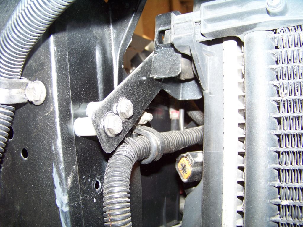
This was one of the easier parts of the swap to do. I discovered in tearing down the GTO donor that it had a power steering cooler. I thought why not, if they thought it important to have one I will move that over too. This picture shows the mounting of the cooler in front of the core support. As you can see it was fairly simple to mount, I just made a flat strap to support the cooler at it's existing bolt locations and to the core support upright.
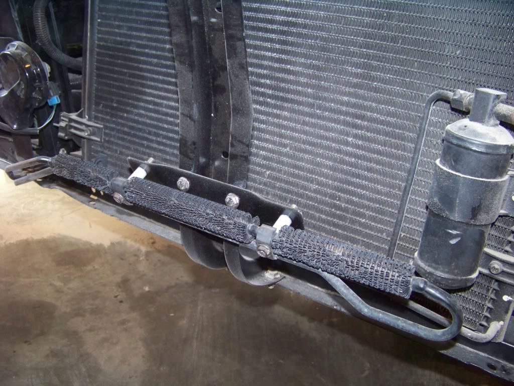
As mentioned in a previous post I swapped the old steering box with one from a 96 Jeep Grand Cherokee which is a direct bolt in and quickens the steering. So I had to connect the power steering lines from this steering box to the power steering pump on the GTO donor. I used two hoses from NAPA, part number 7-1832 for the pressure side and part number 7-1717 for the return side. This isn't a real great picture but this shows these lines installed on the gearbox and power steering pump. These lines need minor tweaking to get them installed.
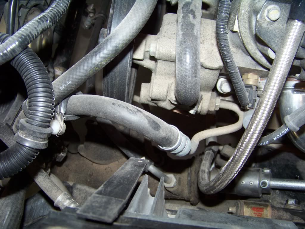
I also bought some power steering return hose to connect to the cooler hardlines which come in around the passenger side of the radiator as shown in the first picture. These run along the rear side of the bottom of the core support, you can just see one line and it's clamp just to the left of the power steering pump pulley in the picture above.
This was one of the easier parts of the swap to do. I discovered in tearing down the GTO donor that it had a power steering cooler. I thought why not, if they thought it important to have one I will move that over too. This picture shows the mounting of the cooler in front of the core support. As you can see it was fairly simple to mount, I just made a flat strap to support the cooler at it's existing bolt locations and to the core support upright.
As mentioned in a previous post I swapped the old steering box with one from a 96 Jeep Grand Cherokee which is a direct bolt in and quickens the steering. So I had to connect the power steering lines from this steering box to the power steering pump on the GTO donor. I used two hoses from NAPA, part number 7-1832 for the pressure side and part number 7-1717 for the return side. This isn't a real great picture but this shows these lines installed on the gearbox and power steering pump. These lines need minor tweaking to get them installed.
I also bought some power steering return hose to connect to the cooler hardlines which come in around the passenger side of the radiator as shown in the first picture. These run along the rear side of the bottom of the core support, you can just see one line and it's clamp just to the left of the power steering pump pulley in the picture above.
11-04-2012, 12:38 PM
#50
TECH Apprentice
Join Date: May 2006
Location: South Florida
Posts: 361
Likes: 0
Received 0 Likes
on
0 Posts

Build is lookin great dude, nice attention to detail. I have an odd question for you. I have the same car and I'm nearing the end of my build but I have misplaced my hood hardware. I've tried to google what size the hood bolts are but have come up empty. If you could tell me the thread and length I would greatly appreciate it.
Regards,
Ryan
Regards,
Ryan
11-04-2012, 01:16 PM
#51
Staging Lane
Thread Starter
Ryan,
Thanks for the comment.
I bought the hinge bolt set from OPG (part CH21555-ST, currently on sale for $22.95). Note their comment on the webpage about the incorrect pointy bolt others sell.
I went out to my shop and checked them and they are 3/8-16 bolts 3/4" long. It appears as though the same bolt is used for hinge to fender and hinge to hood.
Phil
 12-01-2012, 04:02 PM
#53
Staging Lane
Thread Starter
An update for my build thread for those of you who may have wondered what's happening . . .
Transmission Cooler Lines
Obviously the transmission cooling lines from the GTO donor weren�t going to fit exactly into the Lemans, but I did manage to use most of them. I cut a small section out in each line from where they went around the driver�s side header and joined the lines with some AN fittings and braided hose. The fittings I used were -6 AN 3/8 hard tube fitting adapters (part number SUM-2200077B at Summit, four required) for the cut ends of the tubes and -6 AN straight hose ends (part number SUM-220690B, again four required) and two appropriate lengths of -6 AN hose.
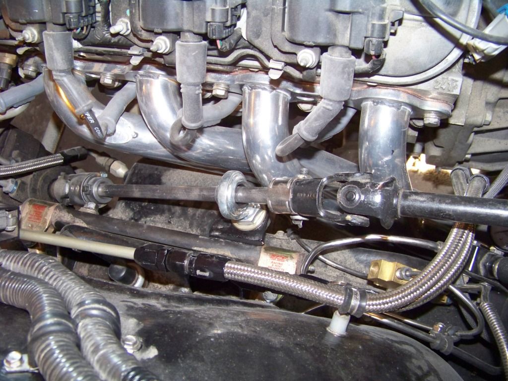
I thought about doing the whole thing in AN lines, but it would have been a lot more expensive due to the special adapter fittings required at the radiator and transmission.
This picture also shows the steering linkage which I hope to discuss soon when I get into the interior installation.
Transmission Cooler Lines
Obviously the transmission cooling lines from the GTO donor weren�t going to fit exactly into the Lemans, but I did manage to use most of them. I cut a small section out in each line from where they went around the driver�s side header and joined the lines with some AN fittings and braided hose. The fittings I used were -6 AN 3/8 hard tube fitting adapters (part number SUM-2200077B at Summit, four required) for the cut ends of the tubes and -6 AN straight hose ends (part number SUM-220690B, again four required) and two appropriate lengths of -6 AN hose.
I thought about doing the whole thing in AN lines, but it would have been a lot more expensive due to the special adapter fittings required at the radiator and transmission.
This picture also shows the steering linkage which I hope to discuss soon when I get into the interior installation.
12-01-2012, 05:19 PM
#54
Staging Lane
Thread Starter
Cooling System
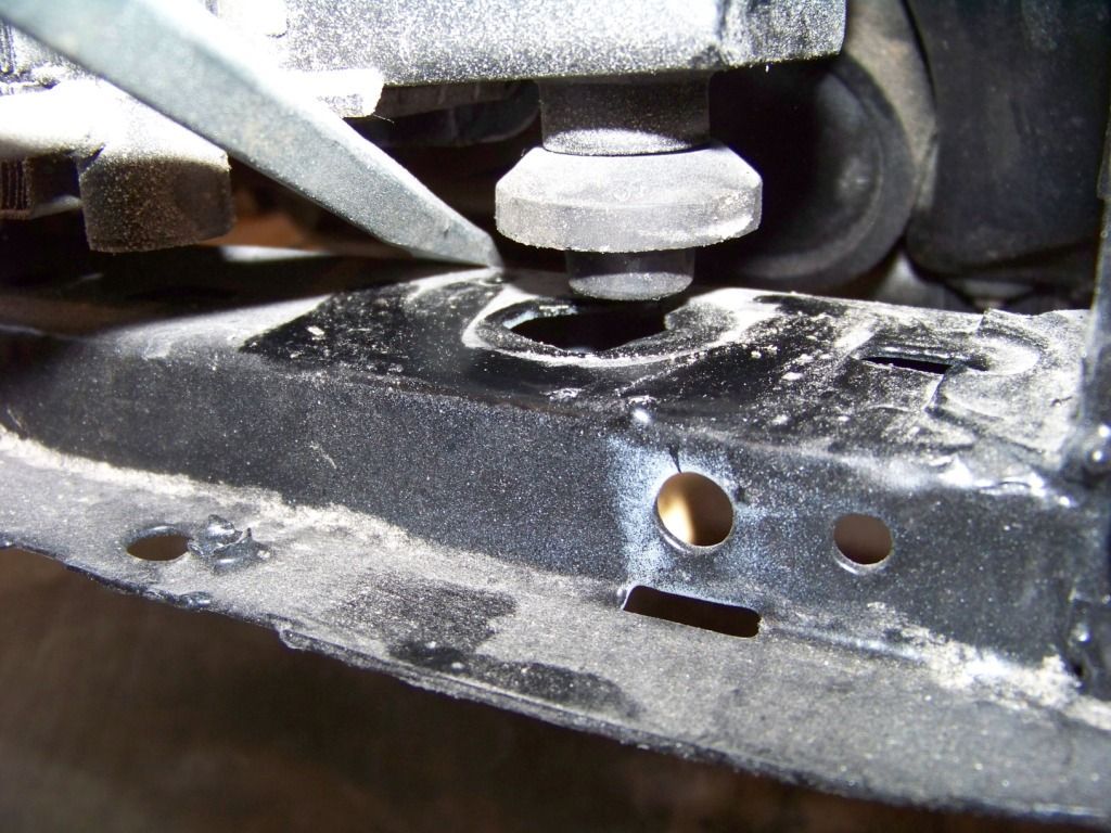
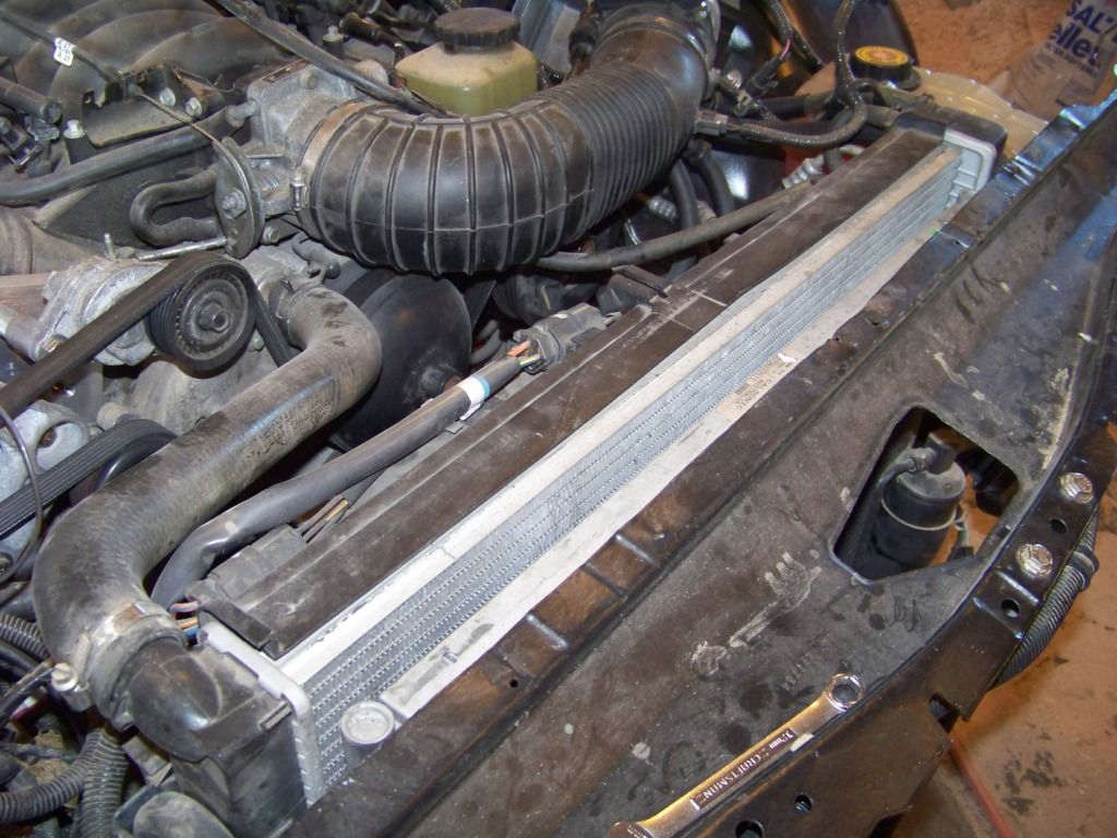
I was determined to use as many components from the GTO donor as possible and that included the cooling system. The new GTO radiator is slightly taller but several inches narrower than the opening in the Leman’s core support. The GTO radiator apparently just sits in its core support by gravity. So I duplicated how it was mounted into the Lemans. Two posts with rubber bushings protrude from the bottom of the radiator and rest in corresponding holes (upper right below) in the bottom of the new GTO’s core support, see picture below.
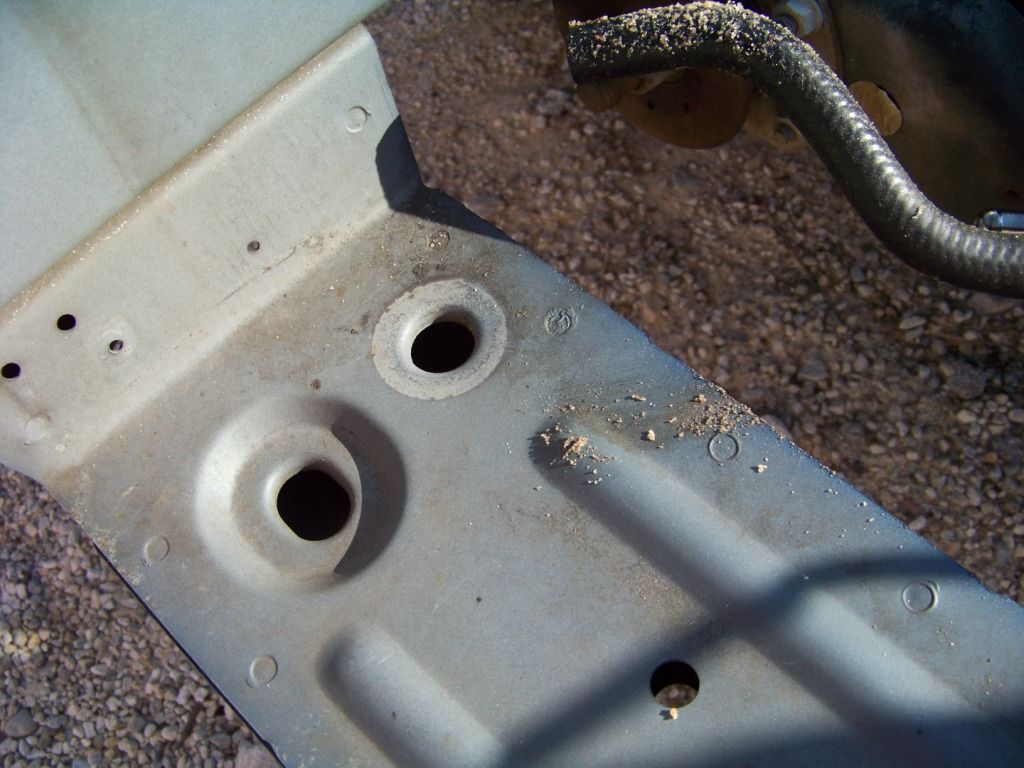
I drilled matching holes in the bottom of the Leman’s core support as shown. In the picture below I am using a screwdriver shaft to hold the radiator up so you can see how it rests into the new holes. Excuse the dust, woodworking and car building don't mix very well.
On the outside upper edges of the radiator are rubber doughnut shaped bushings. These slide into u-shaped brackets attached to the core support. These u-shaped brackets were removed from the GTO donor and modified to fit into the Lemans. I welded straps to the u-shaped supports and mounted them on the Leman’s core support with bolts, and nylon spacers.
I noted the Leman’s core support leaned forward slightly at the top. I used this to my advantage when I mounted the new GTO’s radiator. It sits in the new holes in the bottom of the core support and raises above and behind the core support at the top so the radiator ends up being fairly vertical. I am not sure what’s going to happen at the top of the core support, I removed the upper sheet metal panel when I reworked the core support. The sheet metal will have to be trimmed, and I may come up with a radiator cover at some point.
By the way, the AC condenser and electric fans were reinstalled onto the radiator just as they were on the GTO donor. It was easy-peasy because they both attach directly to the radiator so there wasn't any fabrication to do. They both just slide down onto L-shaped brackets on the radiator and snap into place. There is ample room in front and behind the radiator for these components.
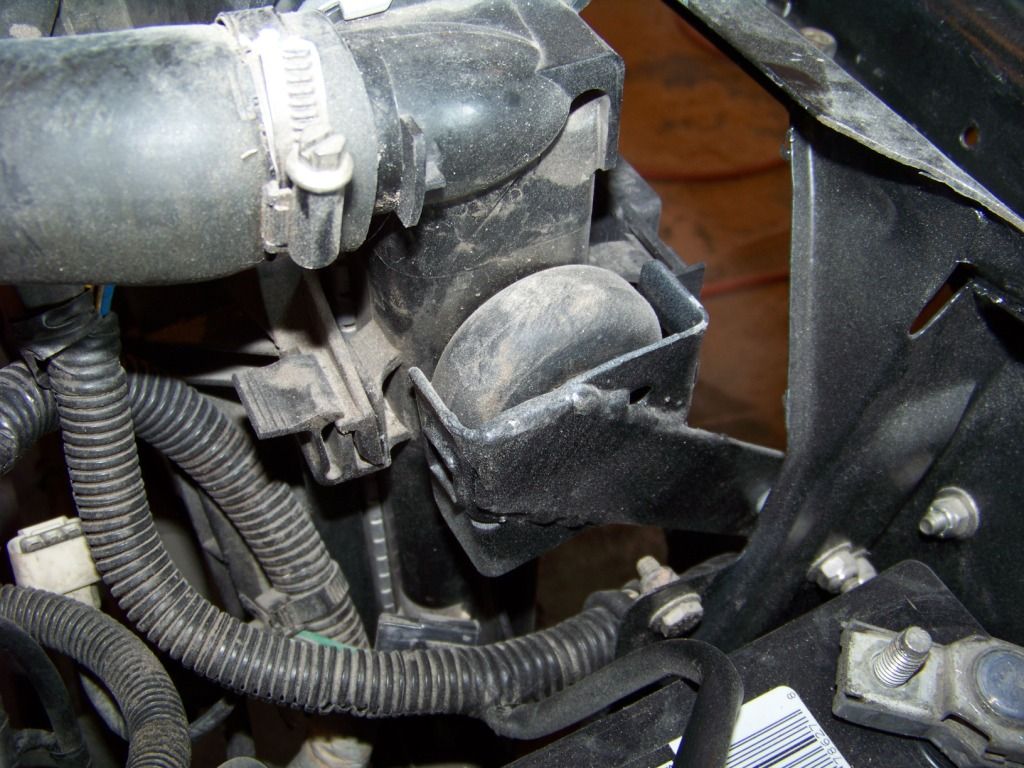
This last picture shows the installation of the coolant recovery tank. My original thought was to get this mounted in a driver’s side location in such a way that all the connections would route well to mating components. But I have since discovered that I may have mounted it to low, which is important as I believe the tank helps determine the level of the coolant in the system and mine is therefore may be too low. I will be looking into ways to remedy this issue. Can anyone tell me about what level this tank should be in as compared to the radiator? If I had known it was important I would have measure it before I removed the components from the GTO donor.
As far as hoses go I was able to use all of the existing radiator and heater hoses from the GTO donor. This will just make things that much easier when I go to the parts store for replacements, I will just tell them it's for a 2004 GTO.
I will discuss the heater hose connections through the firewall and onto the HVAC unit further when I talk about the interior installation.
I was determined to use as many components from the GTO donor as possible and that included the cooling system. The new GTO radiator is slightly taller but several inches narrower than the opening in the Leman’s core support. The GTO radiator apparently just sits in its core support by gravity. So I duplicated how it was mounted into the Lemans. Two posts with rubber bushings protrude from the bottom of the radiator and rest in corresponding holes (upper right below) in the bottom of the new GTO’s core support, see picture below.
I drilled matching holes in the bottom of the Leman’s core support as shown. In the picture below I am using a screwdriver shaft to hold the radiator up so you can see how it rests into the new holes. Excuse the dust, woodworking and car building don't mix very well.
On the outside upper edges of the radiator are rubber doughnut shaped bushings. These slide into u-shaped brackets attached to the core support. These u-shaped brackets were removed from the GTO donor and modified to fit into the Lemans. I welded straps to the u-shaped supports and mounted them on the Leman’s core support with bolts, and nylon spacers.
I noted the Leman’s core support leaned forward slightly at the top. I used this to my advantage when I mounted the new GTO’s radiator. It sits in the new holes in the bottom of the core support and raises above and behind the core support at the top so the radiator ends up being fairly vertical. I am not sure what’s going to happen at the top of the core support, I removed the upper sheet metal panel when I reworked the core support. The sheet metal will have to be trimmed, and I may come up with a radiator cover at some point.
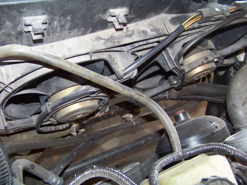
By the way, the AC condenser and electric fans were reinstalled onto the radiator just as they were on the GTO donor. It was easy-peasy because they both attach directly to the radiator so there wasn't any fabrication to do. They both just slide down onto L-shaped brackets on the radiator and snap into place. There is ample room in front and behind the radiator for these components.
This last picture shows the installation of the coolant recovery tank. My original thought was to get this mounted in a driver’s side location in such a way that all the connections would route well to mating components. But I have since discovered that I may have mounted it to low, which is important as I believe the tank helps determine the level of the coolant in the system and mine is therefore may be too low. I will be looking into ways to remedy this issue. Can anyone tell me about what level this tank should be in as compared to the radiator? If I had known it was important I would have measure it before I removed the components from the GTO donor.
As far as hoses go I was able to use all of the existing radiator and heater hoses from the GTO donor. This will just make things that much easier when I go to the parts store for replacements, I will just tell them it's for a 2004 GTO.
I will discuss the heater hose connections through the firewall and onto the HVAC unit further when I talk about the interior installation.
Last edited by fsdproject; 12-01-2012 at 05:21 PM. Reason: misspelling
12-02-2012, 08:54 AM
#55
TECH Fanatic
Your instinct is correct, the surge tank/fluid reservoir should be the highest point in the system. Be sure to take into account the coolant lines to the throttle body to prevent an air pocket. I love this build, are you going to have the car running and driving in time to make the Goodguys event in Columbus this coming July? Now that we are close enough I have made the plans to attend. Haven't gone since my brother in law took the last car from our shop (his own) as an entry in the Street Machine of the Year competition.
12-02-2012, 04:47 PM
#56
Staging Lane
Thread Starter
oldgoat69:
I really appreciate all of your comments and I am impressed how much you are following my build. I am hoping many others also appreciate and find useful what I am doing to make it worthwhile documenting it like this. I seem to get a fair number of thread views, so I am guessing lots more are looking but not commenting and that's okay. I also maintain the same build thread on pro-touring.com, but don't seem to get as much interest there for some reason.
Thanks for the response on the surge tank, I am going to get that relocated before I run the engine again. I may have to move the ECM and/or go to a Corvette surge tank which mounts on top of the fender and is really shallow, this GTO one is kinda of a weird shape.
My son and I have gone to the Goodguys Columbus event the last two years and leave overwhelmed with the level of craftsmanship displayed and the number and variety of entries. We are fortunate to only live about an hour from Columbus so it's a fairly easy day (besides usually being HOT!).
I would LOVE to get the car done (or mostly done) by next summer for all the car related activities. One of my goals is to do the Hot Rod Power Tour, and car shows next summer including Columbus. Would love to keep in touch and then maybe meet you at one of those shows, I bet we would have a lot of interesting stories to share. If your travels ever take you into southwest Ohio send me a PM, I will give you the $10 shop tour for no charge.
As I have mentioned here before, my build is further along than my thread, I am always trying to catch the thread up. It's getting closer but not quite there yet. I did have the dash installed and engine running a few months ago, but removed the dash to finish everything on the firewall and do the sound deadener. I am currently getting all the items that go through the firewall figured out such as AC, heat, harnesses, gas and brake pedal, and steering; and have those mostly figured out and hope to document those in the near future. Boy, I probably spent 2-3 weeks recently researching air conditioning tubing and fittings, that's a whole world onto itself. Then dash goes in permanently along with console, seats to get a functional interior. And on and on.
Thanks again . . .
Phil
12-02-2012, 06:43 PM
#57
TECH Fanatic
I look forward to meeting you in person. We currently live in Lexington, only 3 hours from Columbus. Our kids and grandkids live there so we get that way fairly often. One of these days we can make the trip your way on one of our sightseeing trips.
02-02-2013, 10:27 AM
#58
Staging Lane
Thread Starter
Cooling System Rework
As I mentioned in my previous post about the cooling system, I discovered that I probably originally installed the coolant recovery tank too low. This post shows how I remedied that.
I tried in vain to figure out a way to raise the tank enough, but I wasn�t successful. The only other place I could think of was higher up on the inner fender where the ECM was, but then that means I would have to find another place for that and I was happy with where it was. Then it occurred to me that I could lower the radiator. I ended up doing that and raising the coolant recover tank.
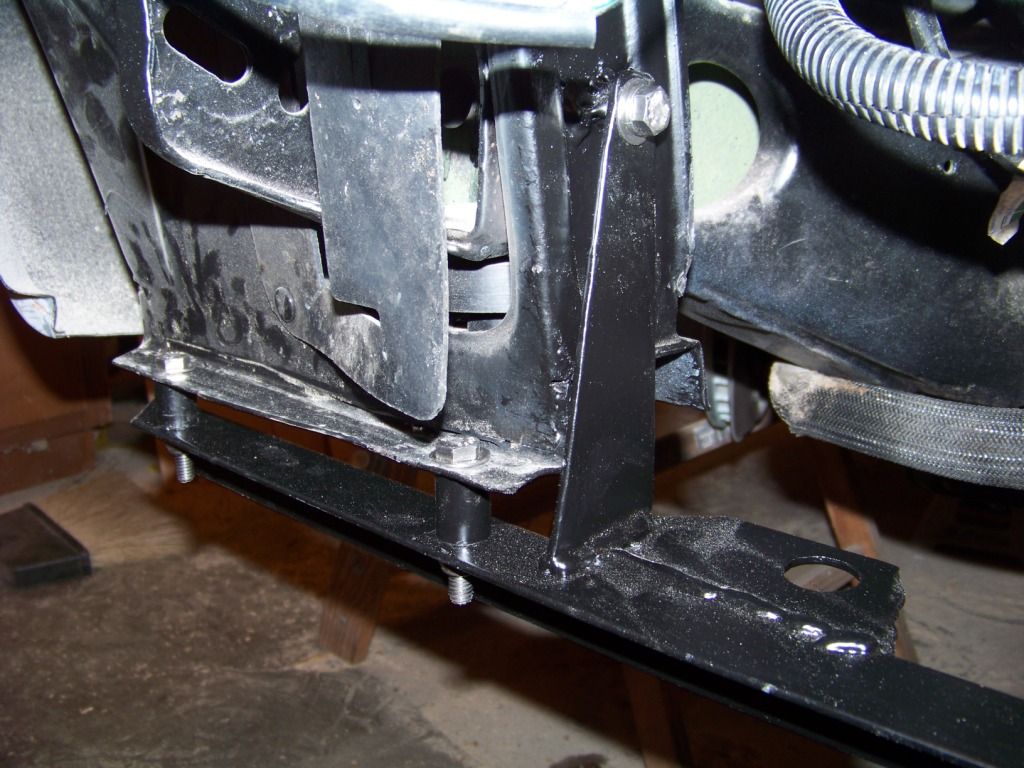
I cut the center part of the lower channel from the core support and made a new lower radiator support from angle iron and tabs welded on as required to support the GTO radiator.
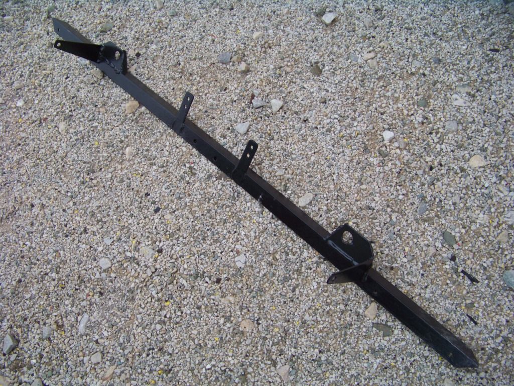
This new support was attached with bolts and spacers to the bottom on the core support as shown. This ended up lowering the radiator about 2 3/8 inches. As a bonus, the radiator no longer sticks up above the top of the core support. The top support brackets for the radiator were also moved down an equal amount. The picture below shows the attachment of the new lower channel on one side, the other side is just the opposite.
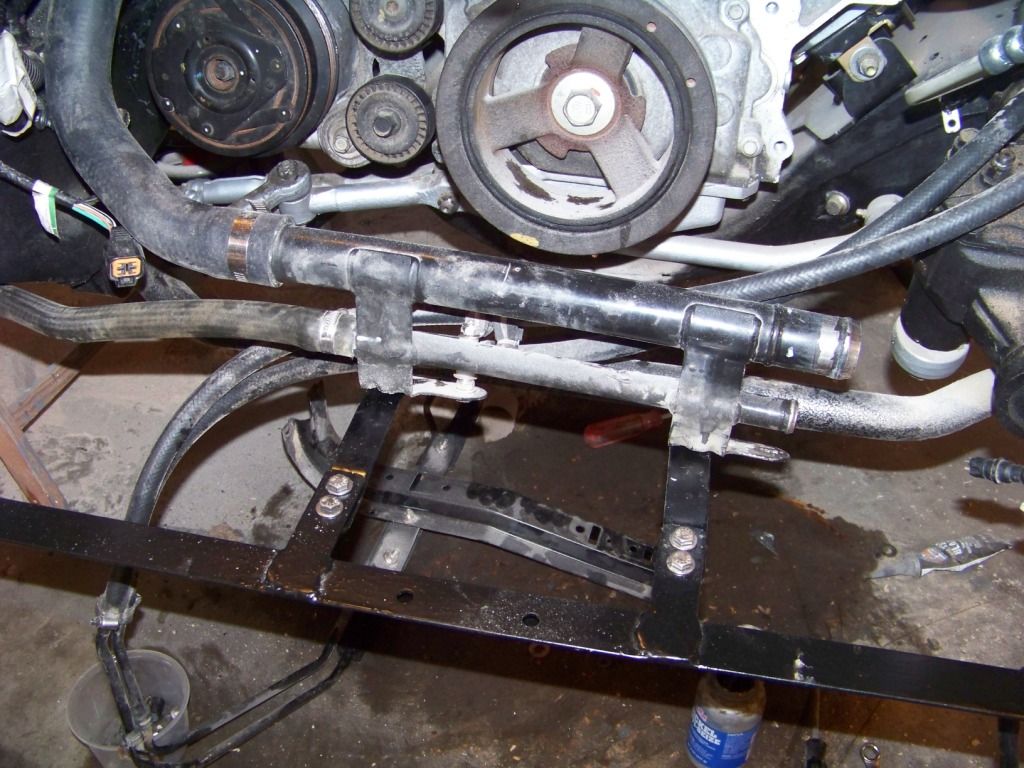
The picture below shows the support and installation for the coolant transfer tubes between the lower part of the radiator and the engine. This assembly was on the GTO so I also moved it over so I could use the GTO's lower hoses.
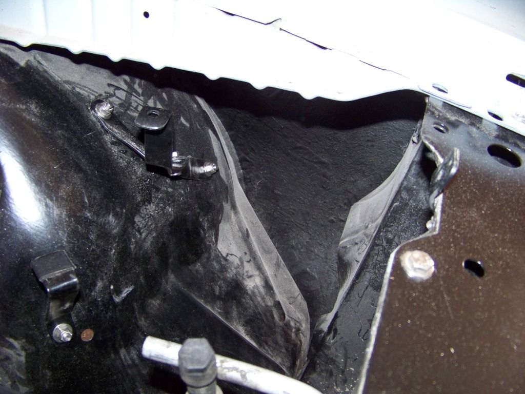
The coolant recovery tank was reinstalled in approximately the same position it was before except about 2 inches higher. The picture below shows the support brackets I fabricated and installed to support the tank. This is looking down into the area between the driver's side inner fender and the core support. The brackets are attached to the inner fender and core support. The bracket in the lower left corner of the picture is simple flat support the recovery tank rests on to support it.
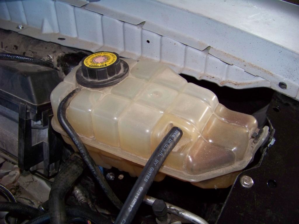
The following picture shows the recovery tank installed. The tank is now higher than the radiator and engine so the system should be filled correctly in the engine and radiator.
As part of this effort since the cooling system was drained I got the HVAC system installed in the interior and connected all of the heater hoses. I will document that in a future post.
As I mentioned in my previous post about the cooling system, I discovered that I probably originally installed the coolant recovery tank too low. This post shows how I remedied that.
I tried in vain to figure out a way to raise the tank enough, but I wasn�t successful. The only other place I could think of was higher up on the inner fender where the ECM was, but then that means I would have to find another place for that and I was happy with where it was. Then it occurred to me that I could lower the radiator. I ended up doing that and raising the coolant recover tank.
I cut the center part of the lower channel from the core support and made a new lower radiator support from angle iron and tabs welded on as required to support the GTO radiator.
This new support was attached with bolts and spacers to the bottom on the core support as shown. This ended up lowering the radiator about 2 3/8 inches. As a bonus, the radiator no longer sticks up above the top of the core support. The top support brackets for the radiator were also moved down an equal amount. The picture below shows the attachment of the new lower channel on one side, the other side is just the opposite.
The picture below shows the support and installation for the coolant transfer tubes between the lower part of the radiator and the engine. This assembly was on the GTO so I also moved it over so I could use the GTO's lower hoses.
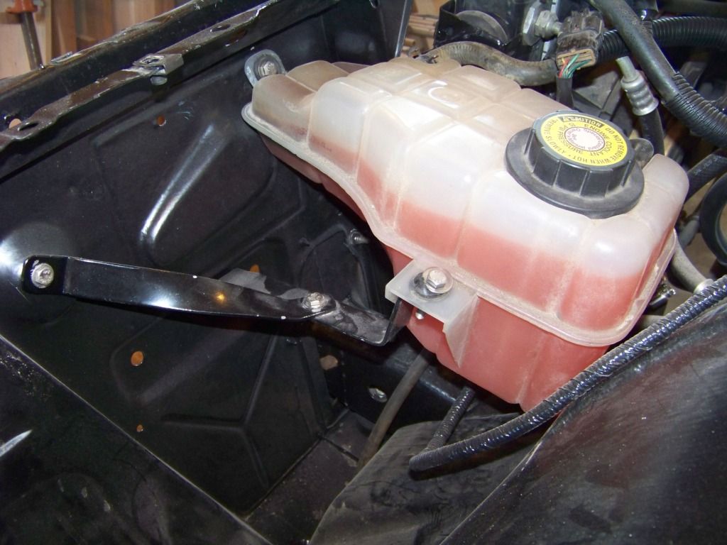
The coolant recovery tank was reinstalled in approximately the same position it was before except about 2 inches higher. The picture below shows the support brackets I fabricated and installed to support the tank. This is looking down into the area between the driver's side inner fender and the core support. The brackets are attached to the inner fender and core support. The bracket in the lower left corner of the picture is simple flat support the recovery tank rests on to support it.
The following picture shows the recovery tank installed. The tank is now higher than the radiator and engine so the system should be filled correctly in the engine and radiator.
As part of this effort since the cooling system was drained I got the HVAC system installed in the interior and connected all of the heater hoses. I will document that in a future post.
Last edited by fsdproject; 02-02-2013 at 10:38 AM. Reason: Added picture and text for coolant transfer tube supports
02-02-2013, 11:47 AM
#59
Staging Lane
Thread Starter
Firewall Interior Side Part One
I wanted to finish up the cooling system, which meant getting the HVAC system in, which meant getting the GTO's dash into the Lemans. But first I wanted to make sure everything needed was routed through or attached to the firewall, it's much easier to do before the dash goes in.
Brake Pedal
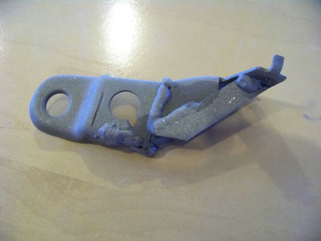
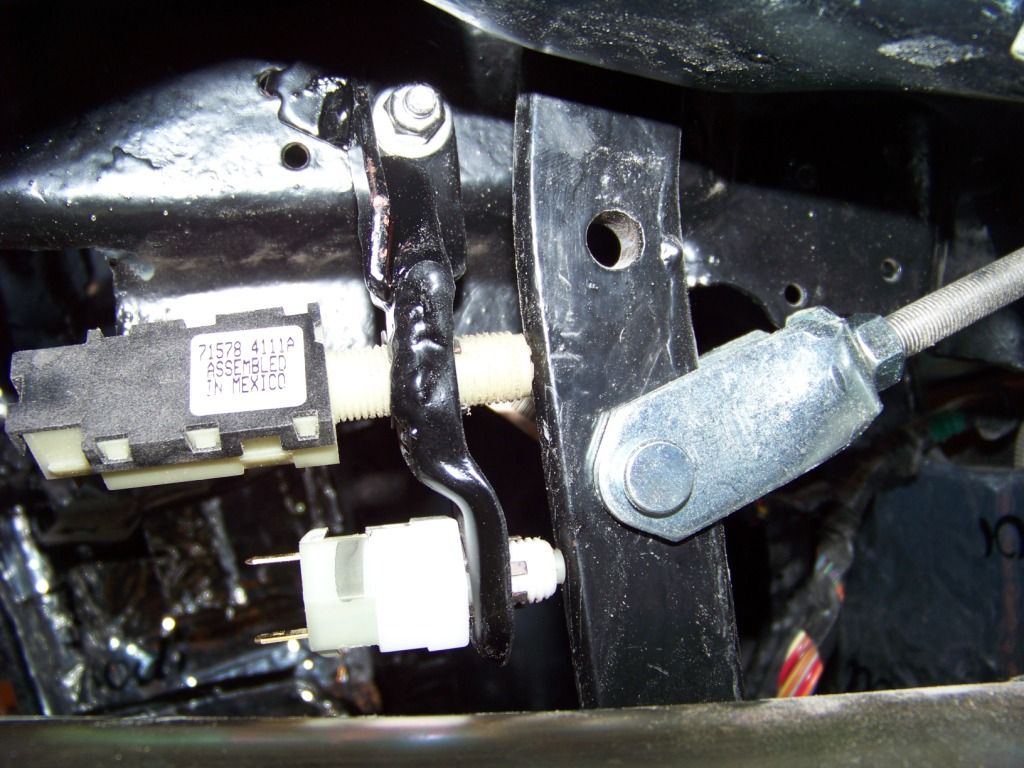
I used the brake pedal and support bracket from the Lemans. The only change I did here was to move the bracket a couple of inches rearward to accommodate the deeper size of the GTO dash. I just did this by using longer bolts and oversize nuts as spacers. The threaded rod from the brake booster was lengthened accordingly. I unfortunately did not take a picture of this. The GTO had two switches on the brake pedal, the Lemans had one. Interestingly, the main brake switch on the GTO appeared to be exactly the same as the one I took from the Lemans. I guess GM uses the same switch 30 plus years later. I did need to support both switches onto the Lemans' bracket, I just welded the lower portion of the GTO's brake switch bracket to the upper part of the Lemans. The pictures below show the modified bracket welded together and installed.
Gas Pedal
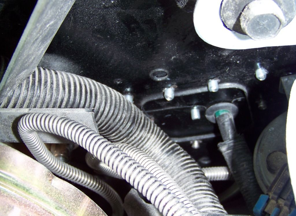
I wanted to use the GTO's gas pedal assembly because it was already designed to work with the throttle cable from the engine. The picture below shows how the gas pedal assembly attached to the GTO's firewall. I needed the round opening in the firewall above the bracket to support the cable end so I cut that portion out as shown.
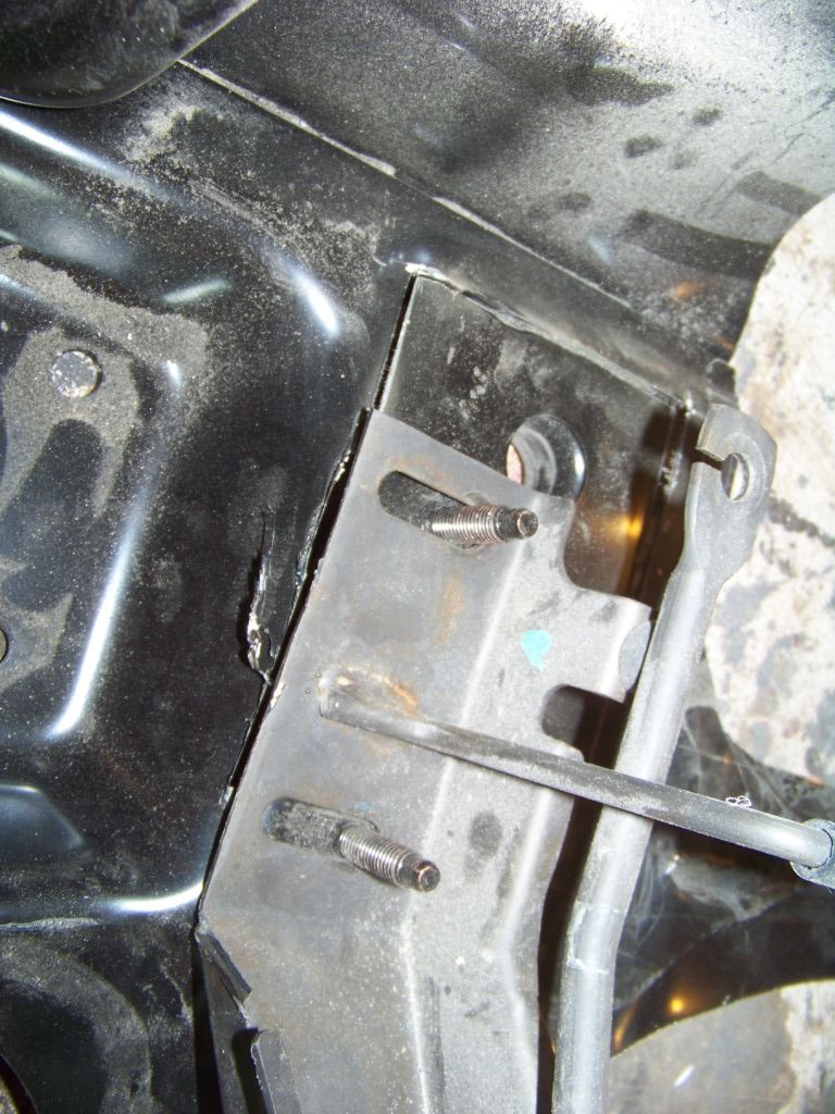
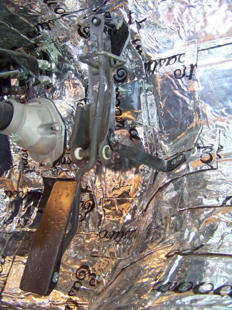
The assembly of the firewall section and the gas pedal assembly was bolted to the firewall in the appropriate place. I added the black bracket as shown to support the lower portion of the pedal assembly. I also thought the gas pedal was too low so I created a new one from welded steel with the pivot point towards the bottom instead of the middle, although I may go back to the GTO's pedal as I play around with things in the interior. In the upper right corner of this picture you also can see how I spaced the brake pedal bracket from the firewall.
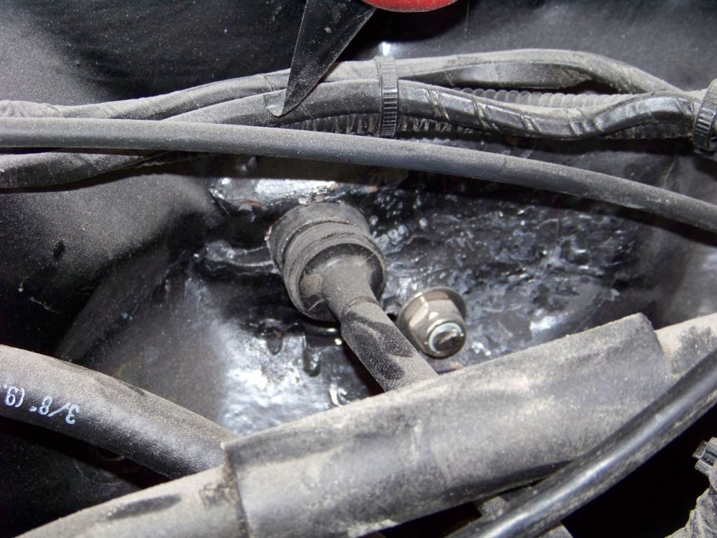
I drilled a 1" dia hole in the Lemans' firewall for the cable end support from the GTO firewall. The picture below shows that on the forward side of the firewall.
Cowl Vent Covers
Since the GTO's HVAC takes fresh air from the upper cowl area, these large openings in the lower sides on the cowl are no longer needed. I made up some simple sheet metal covers and riveted them and sealed them in place on both sides. These were then covered up with sound deadener material.
BCM Installation
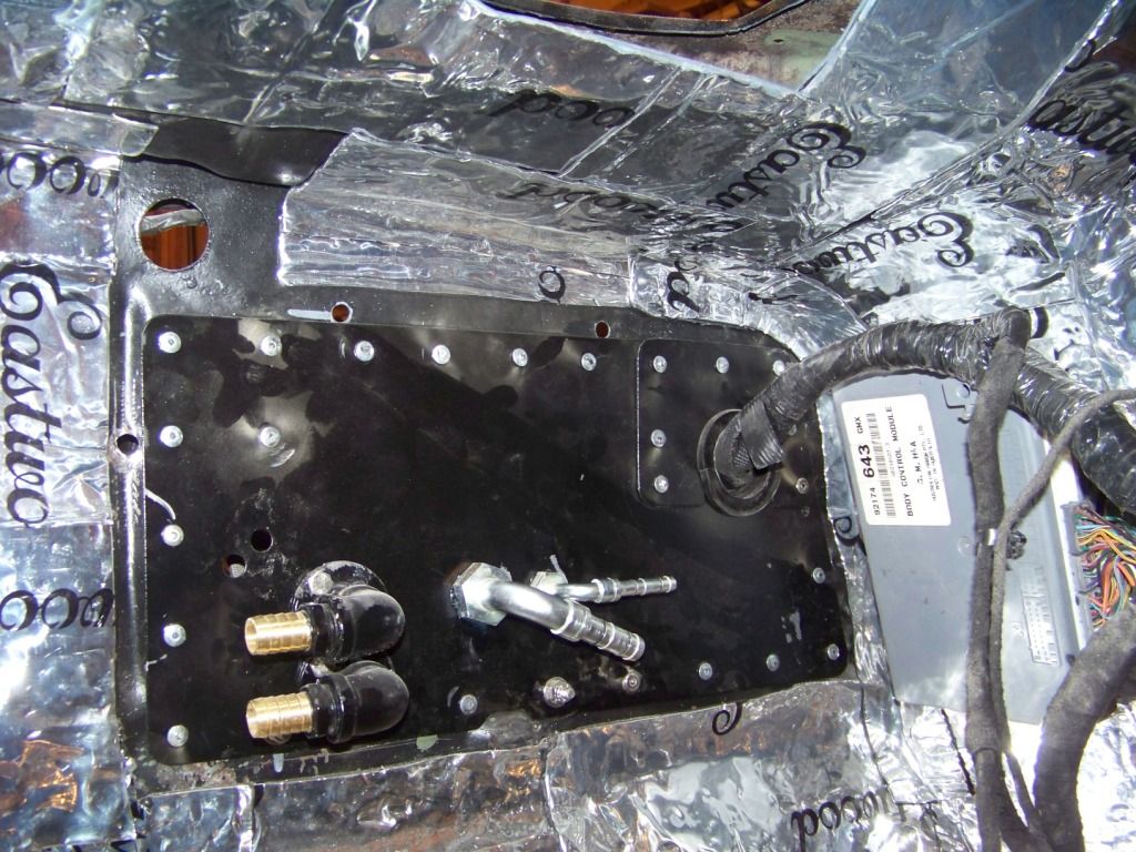
On the GTO the BCM is installed on the interior side of the cowl pasenger side, I did the same. I did a similar thing on the driver's side with the throttle control module. The pictures below shows adding brackets to the BCM, then the BCM attached with sheet metal screws through the new brackets to the cowl cover plates discussed above.

Firewall Part Two will cover wire bundle and HVAC routing through the firewall.
I wanted to finish up the cooling system, which meant getting the HVAC system in, which meant getting the GTO's dash into the Lemans. But first I wanted to make sure everything needed was routed through or attached to the firewall, it's much easier to do before the dash goes in.
Brake Pedal
I used the brake pedal and support bracket from the Lemans. The only change I did here was to move the bracket a couple of inches rearward to accommodate the deeper size of the GTO dash. I just did this by using longer bolts and oversize nuts as spacers. The threaded rod from the brake booster was lengthened accordingly. I unfortunately did not take a picture of this. The GTO had two switches on the brake pedal, the Lemans had one. Interestingly, the main brake switch on the GTO appeared to be exactly the same as the one I took from the Lemans. I guess GM uses the same switch 30 plus years later. I did need to support both switches onto the Lemans' bracket, I just welded the lower portion of the GTO's brake switch bracket to the upper part of the Lemans. The pictures below show the modified bracket welded together and installed.
Gas Pedal
I wanted to use the GTO's gas pedal assembly because it was already designed to work with the throttle cable from the engine. The picture below shows how the gas pedal assembly attached to the GTO's firewall. I needed the round opening in the firewall above the bracket to support the cable end so I cut that portion out as shown.
The assembly of the firewall section and the gas pedal assembly was bolted to the firewall in the appropriate place. I added the black bracket as shown to support the lower portion of the pedal assembly. I also thought the gas pedal was too low so I created a new one from welded steel with the pivot point towards the bottom instead of the middle, although I may go back to the GTO's pedal as I play around with things in the interior. In the upper right corner of this picture you also can see how I spaced the brake pedal bracket from the firewall.
I drilled a 1" dia hole in the Lemans' firewall for the cable end support from the GTO firewall. The picture below shows that on the forward side of the firewall.
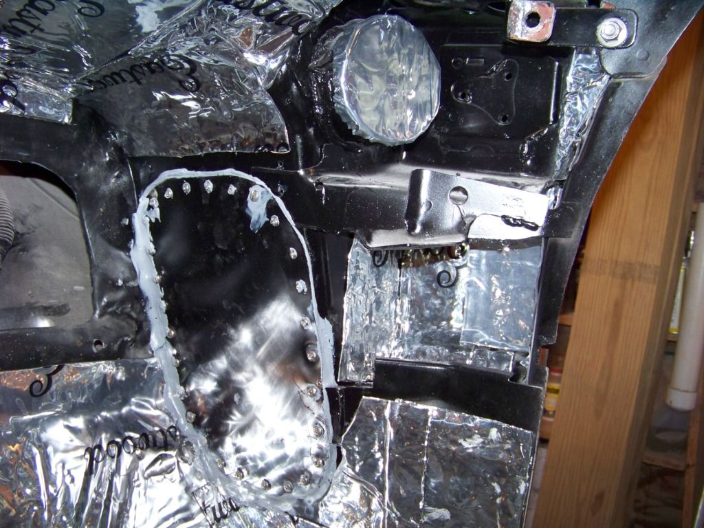
Cowl Vent Covers
Since the GTO's HVAC takes fresh air from the upper cowl area, these large openings in the lower sides on the cowl are no longer needed. I made up some simple sheet metal covers and riveted them and sealed them in place on both sides. These were then covered up with sound deadener material.
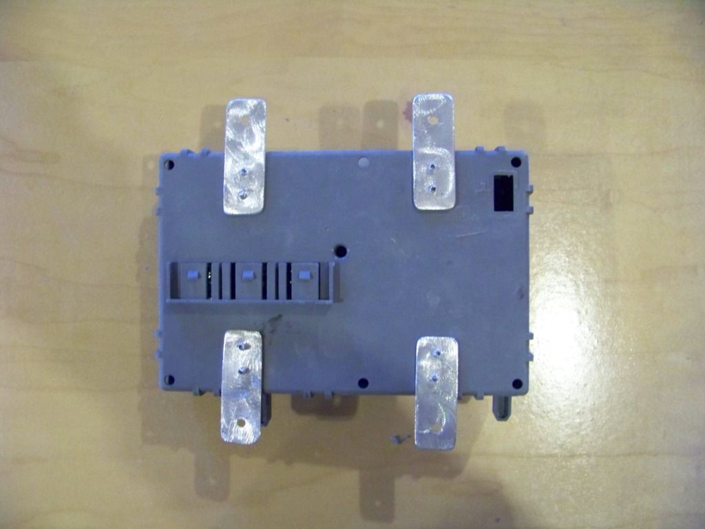
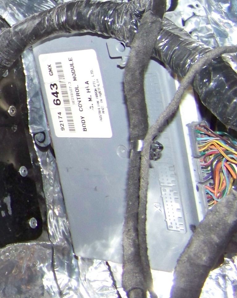
BCM Installation
On the GTO the BCM is installed on the interior side of the cowl pasenger side, I did the same. I did a similar thing on the driver's side with the throttle control module. The pictures below shows adding brackets to the BCM, then the BCM attached with sheet metal screws through the new brackets to the cowl cover plates discussed above.
Firewall Part Two will cover wire bundle and HVAC routing through the firewall.
Last edited by fsdproject; 02-02-2013 at 09:08 PM. Reason: grammer
02-02-2013, 02:12 PM
#60
Staging Lane
Thread Starter
Firewall Interior Side Part Two
I then needed to get two wire bundles and four HVAC connections through the firewall.
Driver's side wire bundle
A smaller wire bundle from the GTO donor goes from under the hood to the dash area on the driver's side. I used the existing rectangular hole in the firewall that was originally used for the fuse block and connection to the Lemans' wire bundle. I needed to find a way to seal the opening around the existing hole. There are existing split seals available, but they didn't really work well for this situation. I did use their design concept in what I came up with.
I made a two-piece cover that could be installed around the wire bundle which was already routed, I didn't want to remove all of the connectors just to route it through a grommet. The cover is made from sheet metal, the grommet is just an appropriately sized rubber grommet I got from Lowes. I cut the grommet in half and put each half into each half of the cover plates. The two plates overlap each other in the middle to sandwich the grommet halves together.
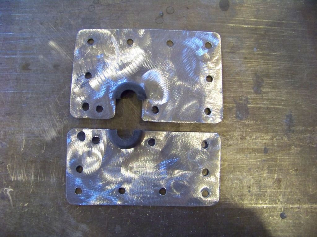
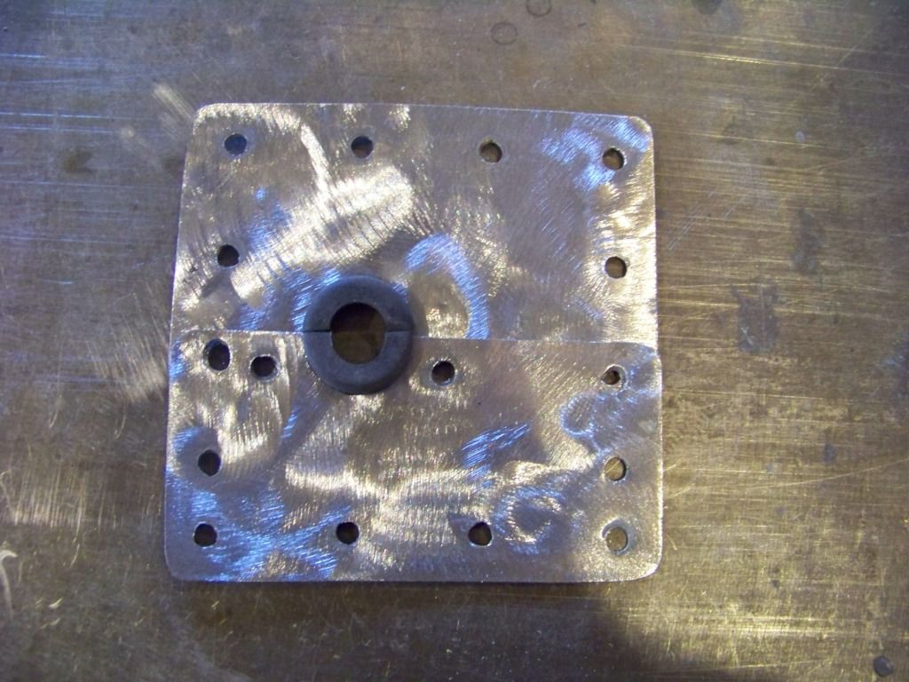
This picture shows the plate/grommet assembly installed from the front of the firewall. The plates are attached to each other and to the firewall with 3/16" steel rivets, the plate will be sealed with seam sealer on the outside and covered with sound deadener on the inside.
Passenger Side Bundle and HVAC bulkhead connections
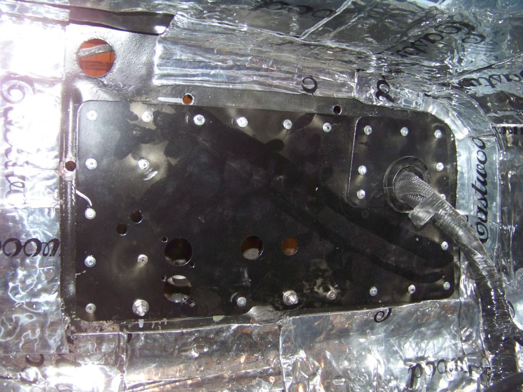
On the passenger side I had a similar situation with the larger bundle on that side, plus I needed to provide for the AC and heater connections. I also had the large rectangular hole in the firewall from where the heater core used to be to cover. I took care of all of these issues with a another two-piece cover plate that also had holes for the AC and heater bulkhead connectors. The picture below shows the two parts of the plate and the grommet I cut in half. The grommet is from McMaster, part number 6359K35. Lowes did not have a grommet this large.
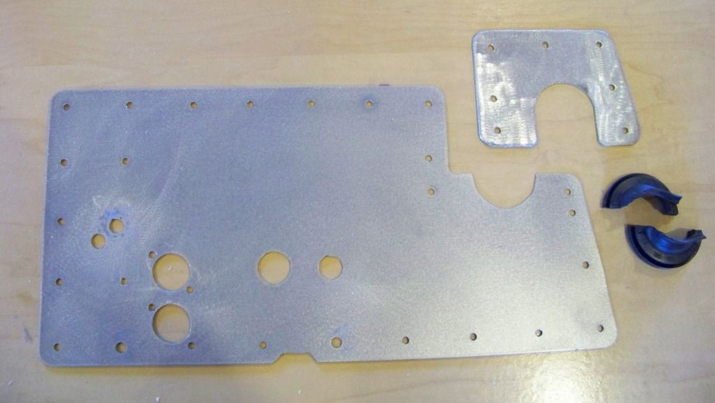
In the above picture the two small holes in the left side of the plate are for vacuum lines between the HVAC unit in the interior and engine and heater valve under the hood. The vacuum lines will be routed through these holes with rubber grommets. The two larger holes positioned vertically are for the heater bulkhead fittings and the remaining two holes to the right are for the AC bulkhead fittings.
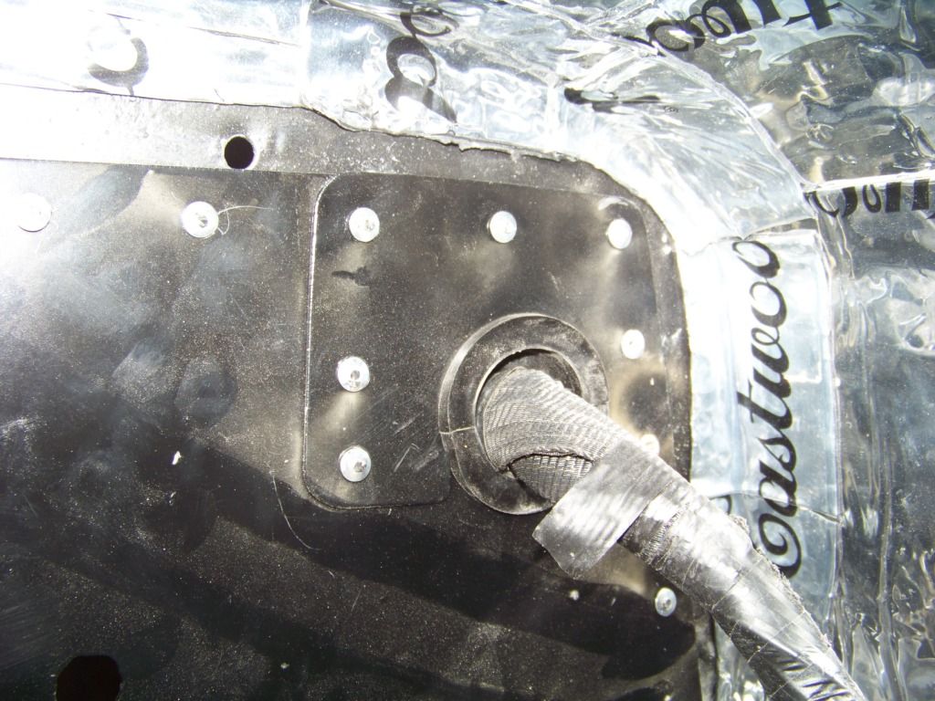
The next picture shows the plate installed around the passenger side wire bundle. The plate was installed with 3/16" steel rivets. The following picture shows a close up of the wire bundle area. Again, the plates overlap to sandwich and hold the two halves of the grommet in place around the bundle.
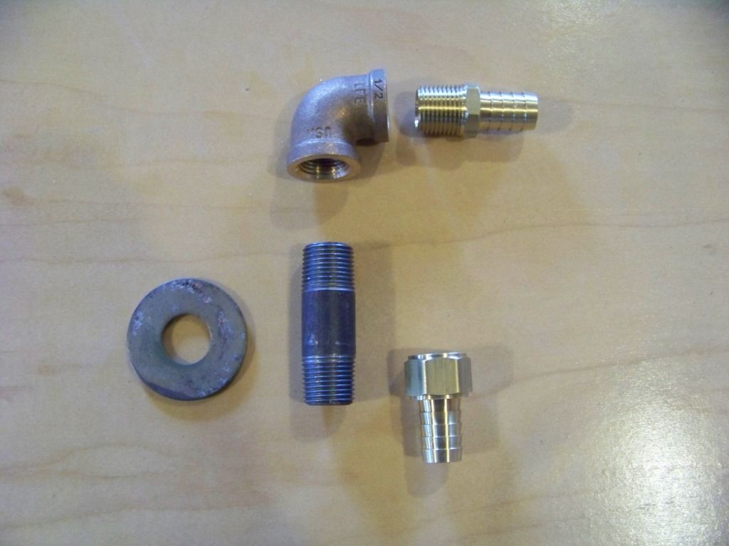
The HVAC unit from the GTO will sit about 4 inches behind the Lemans' firewall. So I needed some short heater hose connections in the interior side between the HVAC unit and the firewall cover plate. Since there were going to be hose connections on both sides I needed heater bulkhead fittings that had barbed ends on each side. I searched extensively online but could not find anything like that, so I made my own. The picture below shows the parts I used. Each fitting is made from a 1/2 inch pipe nipple, large washer to fit around the pipe nipple, a 1/2 inch pipe elbow and two barb fittings as shown. The pipe parts and washer are from Lowes, the barb fittings came from McMaster. They are part numbers 5346K59 and 5346K66. The washer was welded to the pipe nipple and had two holes to facilitate bolting the fitting the the firewall.
The following picture shows the heater and AC bulkhead fittings installed onto the plate.
I did my usual research into AC hoses and fittings and found that there are quite a few ways to go. I stumbled upon the EZ-Clip fittings from Aeroquip and liked them because they are easy for a home builder to make and install. The only special tool required is a pliers. Aeroquip sells the pliers for about $50, but amazingly I found the pliers along with many of the fittings I needed on Ebay for $5 each. I will talk about the AC hoses in a future post but I will give the part numbers for these bulkhead fittings here: FJ3514-0606S and FJ3514-1010S.
When I tried to install the interior heater hose connections I found that I placed the holes in the bulkhead too low, even after what I thought was good measuring and pondering. The fittings were moved up one hole, with another hole being drilled into the plate and the lower hole covered up. They were also rotated about 30 degrees up from vertical. In a future post I will try to show this connection, but it's tough to take pictures under the dash.
I then needed to get two wire bundles and four HVAC connections through the firewall.
Driver's side wire bundle
A smaller wire bundle from the GTO donor goes from under the hood to the dash area on the driver's side. I used the existing rectangular hole in the firewall that was originally used for the fuse block and connection to the Lemans' wire bundle. I needed to find a way to seal the opening around the existing hole. There are existing split seals available, but they didn't really work well for this situation. I did use their design concept in what I came up with.
I made a two-piece cover that could be installed around the wire bundle which was already routed, I didn't want to remove all of the connectors just to route it through a grommet. The cover is made from sheet metal, the grommet is just an appropriately sized rubber grommet I got from Lowes. I cut the grommet in half and put each half into each half of the cover plates. The two plates overlap each other in the middle to sandwich the grommet halves together.
This picture shows the plate/grommet assembly installed from the front of the firewall. The plates are attached to each other and to the firewall with 3/16" steel rivets, the plate will be sealed with seam sealer on the outside and covered with sound deadener on the inside.
Passenger Side Bundle and HVAC bulkhead connections
On the passenger side I had a similar situation with the larger bundle on that side, plus I needed to provide for the AC and heater connections. I also had the large rectangular hole in the firewall from where the heater core used to be to cover. I took care of all of these issues with a another two-piece cover plate that also had holes for the AC and heater bulkhead connectors. The picture below shows the two parts of the plate and the grommet I cut in half. The grommet is from McMaster, part number 6359K35. Lowes did not have a grommet this large.
In the above picture the two small holes in the left side of the plate are for vacuum lines between the HVAC unit in the interior and engine and heater valve under the hood. The vacuum lines will be routed through these holes with rubber grommets. The two larger holes positioned vertically are for the heater bulkhead fittings and the remaining two holes to the right are for the AC bulkhead fittings.
The next picture shows the plate installed around the passenger side wire bundle. The plate was installed with 3/16" steel rivets. The following picture shows a close up of the wire bundle area. Again, the plates overlap to sandwich and hold the two halves of the grommet in place around the bundle.
The HVAC unit from the GTO will sit about 4 inches behind the Lemans' firewall. So I needed some short heater hose connections in the interior side between the HVAC unit and the firewall cover plate. Since there were going to be hose connections on both sides I needed heater bulkhead fittings that had barbed ends on each side. I searched extensively online but could not find anything like that, so I made my own. The picture below shows the parts I used. Each fitting is made from a 1/2 inch pipe nipple, large washer to fit around the pipe nipple, a 1/2 inch pipe elbow and two barb fittings as shown. The pipe parts and washer are from Lowes, the barb fittings came from McMaster. They are part numbers 5346K59 and 5346K66. The washer was welded to the pipe nipple and had two holes to facilitate bolting the fitting the the firewall.
The following picture shows the heater and AC bulkhead fittings installed onto the plate.
I did my usual research into AC hoses and fittings and found that there are quite a few ways to go. I stumbled upon the EZ-Clip fittings from Aeroquip and liked them because they are easy for a home builder to make and install. The only special tool required is a pliers. Aeroquip sells the pliers for about $50, but amazingly I found the pliers along with many of the fittings I needed on Ebay for $5 each. I will talk about the AC hoses in a future post but I will give the part numbers for these bulkhead fittings here: FJ3514-0606S and FJ3514-1010S.
When I tried to install the interior heater hose connections I found that I placed the holes in the bulkhead too low, even after what I thought was good measuring and pondering. The fittings were moved up one hole, with another hole being drilled into the plate and the lower hole covered up. They were also rotated about 30 degrees up from vertical. In a future post I will try to show this connection, but it's tough to take pictures under the dash.
Last edited by fsdproject; 02-04-2013 at 07:01 AM.