
Lsx wiring for dumb ass

 01-05-2013, 07:14 AM
#42
On The Tree
iTrader: (2)

Join Date: Mar 2007
Location: Michigan
Posts: 131
Likes: 0
Received 0 Likes
on
0 Posts
The sensors you need to make it run are:
Crank
Cam
These 2 are for timing and firing of coils & injectors
TPS
IAC
Tjrottle body
MAP (manafold pressure)
You will also need your Speed density sensor since you are not useing a MAF.
O2's are also needed.
Crank
Cam
These 2 are for timing and firing of coils & injectors
TPS
IAC
Tjrottle body
MAP (manafold pressure)
You will also need your Speed density sensor since you are not useing a MAF.
O2's are also needed.
04-08-2013, 02:35 PM
#43
Staging Lane
Thread Starter
okay, went on hiatus for a minute working 82 hrs a week n plan on figuring out how to wire up this fuse panel & OBD scan port. gonna do it the way i saw on another site
 [/IMG]
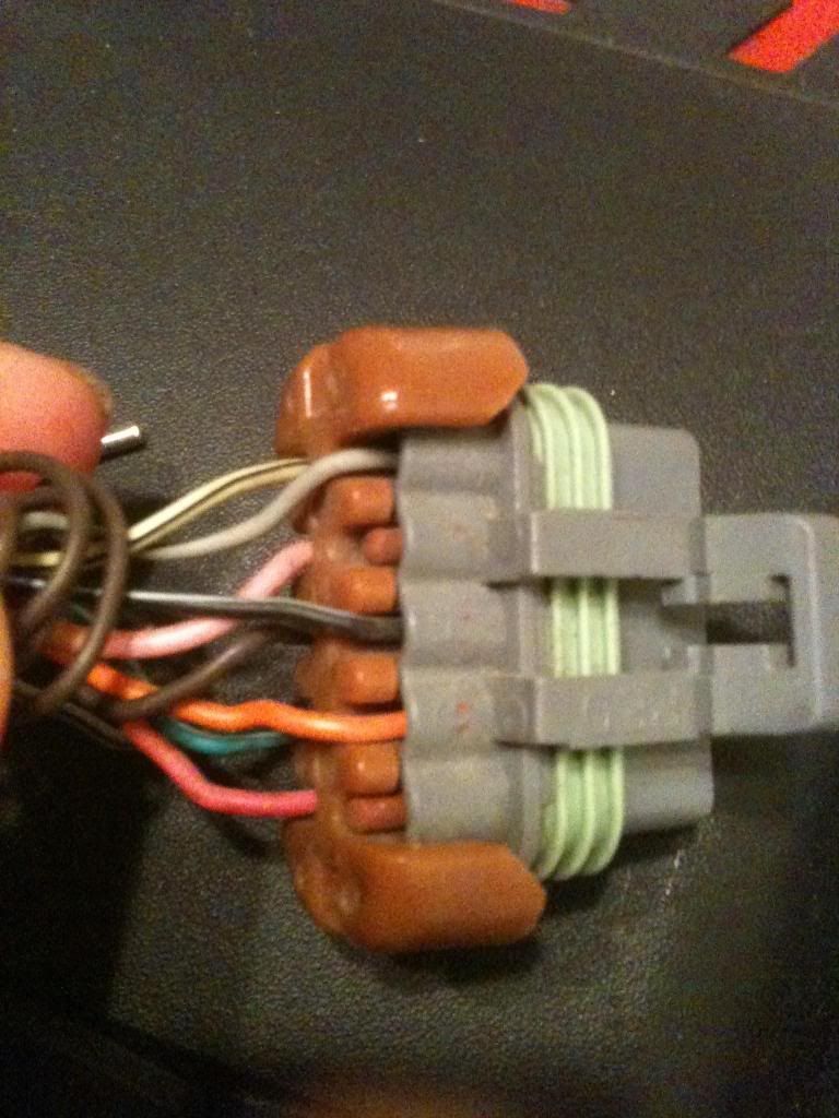 [/IMG]
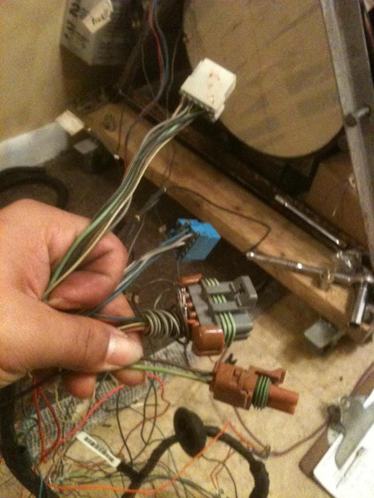 [/IMG]
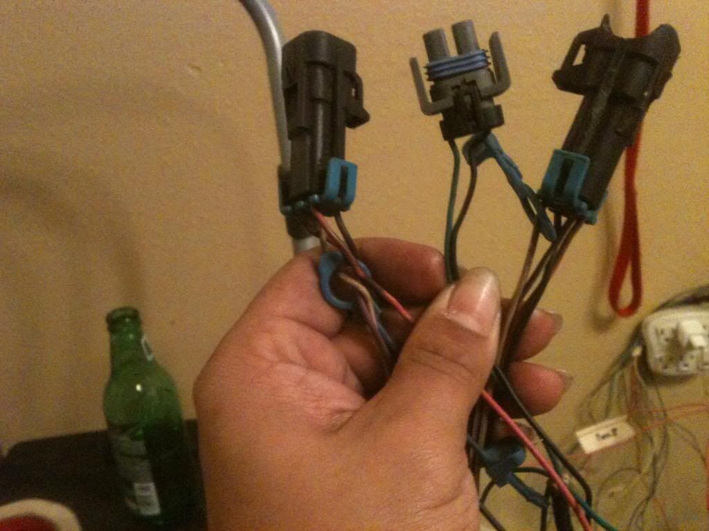 [/IMG]
04-09-2013, 10:56 PM
[/IMG]
04-09-2013, 10:56 PM
#45
Staging Lane
Thread Starter
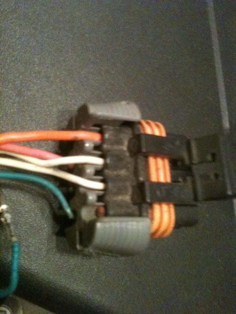
what I am doing?
[IMG]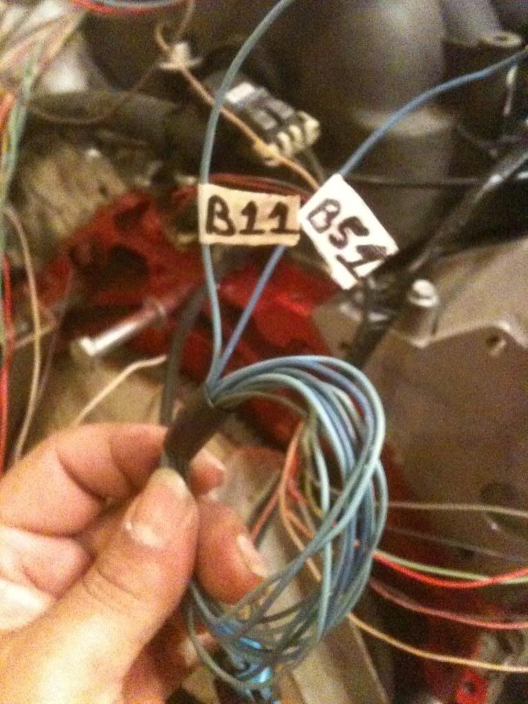 [/IMG]
I have been labeling these as so
[IMG]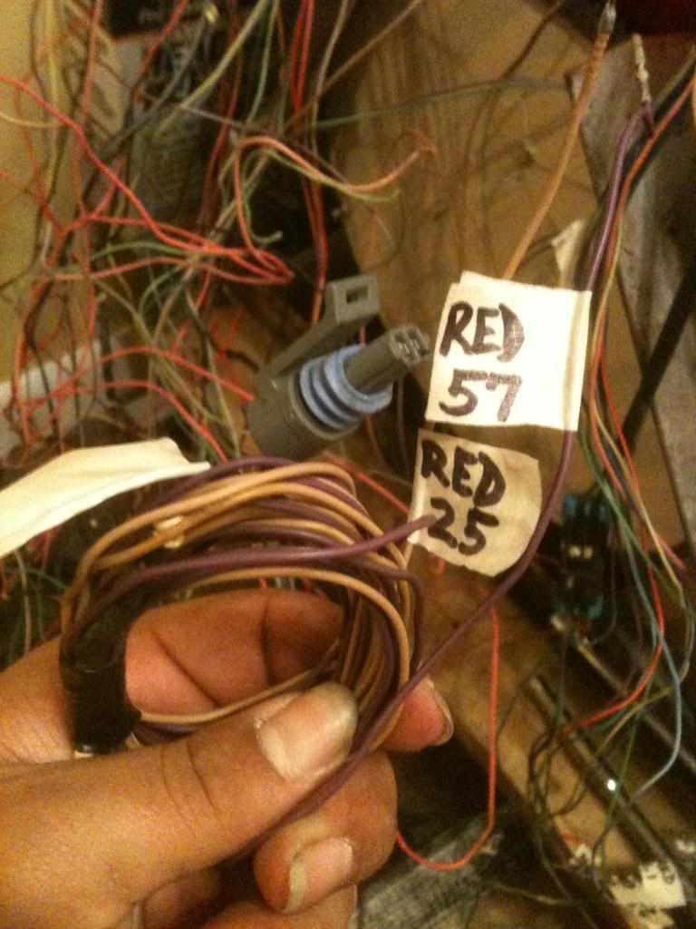 [/IMG]
started wrapping up wires n tucking them tight
[IMG]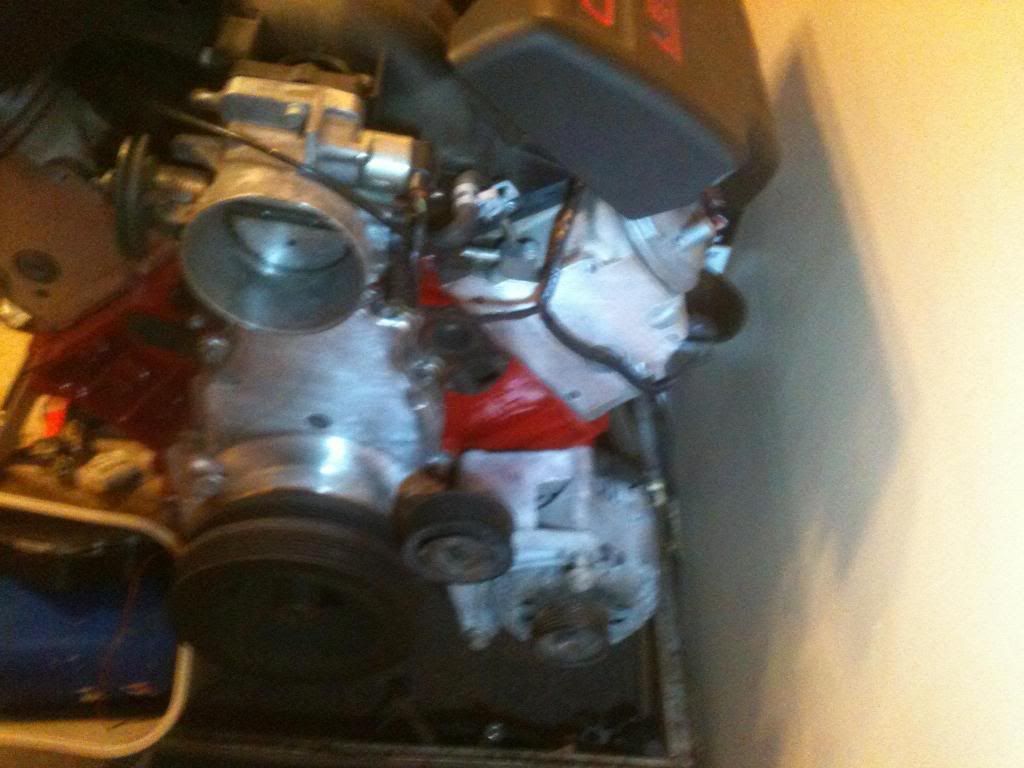 [/IMG]
& this is where I am at now
[IMG]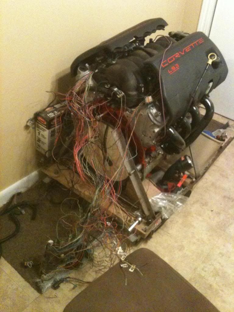 [/IMG]
[IMG]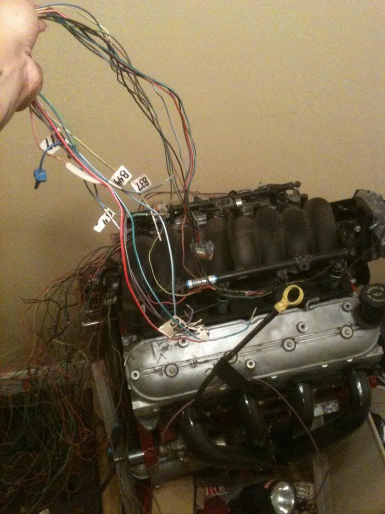 [/IMG]
[IMG]
[/IMG]I have been labeling these as so
[IMG]
[/IMG]started wrapping up wires n tucking them tight
[IMG]
[/IMG]& this is where I am at now
[IMG]
[/IMG][IMG]
[/IMG] 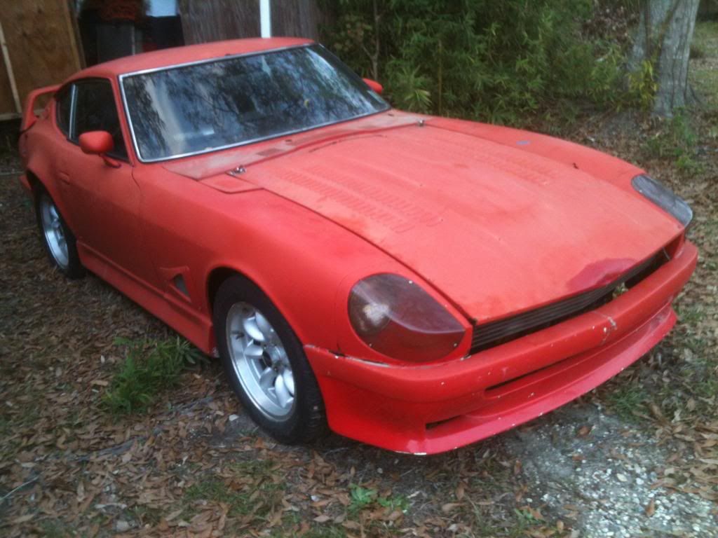 [/IMG]
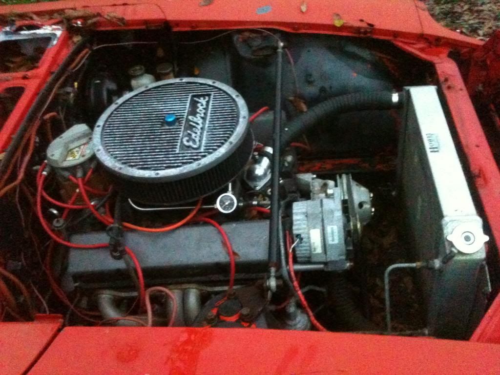 [/IMG]
 [/IMG]
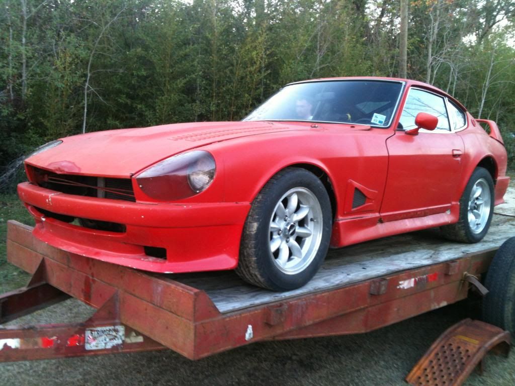 p://[/IMG]
04-10-2013, 09:57 PM
p://[/IMG]
04-10-2013, 09:57 PM
#48
TECH Apprentice
Join Date: Apr 2011
Posts: 390
Likes: 0
Received 0 Likes
on
0 Posts
Moreso than just looking at lt1swap .. think about what a wiring harness does. It routes power, transfers signals to pcm, or grounds.
Split the loom apart, loosely taping or zip-tie in place, and any sensor that you know you need such as a coolant temp, trace those two wires back to the pcm and leave them. If you want to get rid of the bulky 5 pin egr valve connector, take that pin, follow it back.. if it goes to pcm, depin. if it goes to a firewall connector, cut or depin, if it goes to a spliced ground, get rid of it.
Each harness gets easier and easier. the first one is pretty scary but after you get the concept of tracing wires and being about to use an ohm meter to figure out where continuity is, the only reason you need a pin out is to find signals such as fuel pump fans tach etc.
05-04-2013, 09:56 AM
#49
Staging Lane
Thread Starter
So here are some pics of where I am at now
[IMG] [/IMG]
this is the back side of the center dash panel that replaces where ac controls & radio
[IMG] [/IMG]
here is how it will sit in dash( I am going to seal the floor this up comoing week with a truck bed coating before I install the seats
[IMG] [/IMG]
[IMG] [/IMG]
I also have a Cage to add to the old SCCA bolt in cage(that I will weld in) & burn it all in together
this pic is from when i was tearing it apart, i set the seat in there to see if the seat brackets would line up, they didnt.
[IMG] [/IMG]
I hope I extended the harness enough to tuck the ECU inside. routed the wiring close n tight
[IMG] [/IMG]
this is where I am stuck
[IMG]http ://[/IMG]
[IMG] [/IMG]
These wires are left out of the harness to go to fuses & relays & starter etc...
Which one goes where?
So I moved on to seeing how the spacer works with flexplate.
It acts as a snout to hold the converter. Its machined to tight the the converter lines up no problem, but the holes need to be elongated a little.
[IMG] [/IMG]
I was givin a F Body pan to help with the swap, came with windage tray but no pick up tube
[IMG] [/IMG]
when I swap the pan I am going to swap the cam too
[IMG] [/IMG]
This is My buddy Chris standing next to the car to see how low n small it is
[IMG] [/IMG]
will post more soon
[IMG]
 [/IMG]
this is the back side of the center dash panel that replaces where ac controls & radio
[IMG]
 [/IMG]
here is how it will sit in dash( I am going to seal the floor this up comoing week with a truck bed coating before I install the seats
[IMG]
 [/IMG]
[IMG]
 [/IMG]
I also have a Cage to add to the old SCCA bolt in cage(that I will weld in) & burn it all in together
this pic is from when i was tearing it apart, i set the seat in there to see if the seat brackets would line up, they didnt.
[IMG]
 [/IMG]
I hope I extended the harness enough to tuck the ECU inside. routed the wiring close n tight
[IMG]
 [/IMG]
this is where I am stuck
[IMG]http
 ://[/IMG]
[IMG]
 [/IMG]
These wires are left out of the harness to go to fuses & relays & starter etc...
Which one goes where?
So I moved on to seeing how the spacer works with flexplate.
It acts as a snout to hold the converter. Its machined to tight the the converter lines up no problem, but the holes need to be elongated a little.
[IMG]
 [/IMG]
I was givin a F Body pan to help with the swap, came with windage tray but no pick up tube
[IMG]
 [/IMG]
when I swap the pan I am going to swap the cam too
[IMG]
 [/IMG]
This is My buddy Chris standing next to the car to see how low n small it is
[IMG]
 [/IMG]
will post more soon

 05-04-2013, 08:07 PM
#51
Staging Lane
Thread Starter
Okay,
So I have the Harness routed n sealed up
I have have been looking at this pic from LT1swap
[IMG] [/IMG]
the three 12v powered devices are (for me) far right bottom is
#3 passenger side coils/injectors/o2 sensor
#2 driver side coils/injectors/o2 sensor
#1 ?????? I dunno what to put here
The 4th fuse is wired with the Orange wire from pcm that breaks off into two wires(Blue connector pins i call them B20 & B57), it also has a orange wire going to the fuel pump relay(30amp or 40amp rerlay?). This orange wire is always "hot" too?
Does this mean that the PCM & fuel pump relay always have constant source of 12v?
I know the main relay is always hot and has 12v power, a toggle switch acting as a key powers it on & the 3 fuses as well. if i am loking at this right.
The PCM would power up the relay to power up the fuel pump?
If that is correct do I also do the same with High/Low speed fan relays? must they be on two fuses or can they be on one?
I take it the red wire is a 12v constant from the main relay to feed the fuse is "always hot" even when car is not running? Even when parked up for storage?
From Red connector pin 46 is a ground from PCM to Check Engine light?
I put a 12v keyed ignition source on positive side of Check engine light LED?
Blue connector pin 19 Ignition Voltage 1 is pink where does this go?
Red connector pin 15 is this for a dash light/gauge signal or does it need to go to the ALT?
Big Purple wire goes to starter push button?
The gound comes from engine harness to relays or is it batt(-) post to grounds in harness then to relays?
Blue 42 & Blue 58 pins go to OBD port?
So I have the Harness routed n sealed up
I have have been looking at this pic from LT1swap
[IMG]
 [/IMG]
 the three 12v powered devices are (for me) far right bottom is
#3 passenger side coils/injectors/o2 sensor
#2 driver side coils/injectors/o2 sensor
#1 ?????? I dunno what to put here
The 4th fuse is wired with the Orange wire from pcm that breaks off into two wires(Blue connector pins i call them B20 & B57), it also has a orange wire going to the fuel pump relay(30amp or 40amp rerlay?). This orange wire is always "hot" too?
Does this mean that the PCM & fuel pump relay always have constant source of 12v?
I know the main relay is always hot and has 12v power, a toggle switch acting as a key powers it on & the 3 fuses as well. if i am loking at this right.
The PCM would power up the relay to power up the fuel pump?
If that is correct do I also do the same with High/Low speed fan relays? must they be on two fuses or can they be on one?
I take it the red wire is a 12v constant from the main relay to feed the fuse is "always hot" even when car is not running? Even when parked up for storage?
From Red connector pin 46 is a ground from PCM to Check Engine light?
I put a 12v keyed ignition source on positive side of Check engine light LED?
Blue connector pin 19 Ignition Voltage 1 is pink where does this go?
Red connector pin 15 is this for a dash light/gauge signal or does it need to go to the ALT?
Big Purple wire goes to starter push button?
The gound comes from engine harness to relays or is it batt(-) post to grounds in harness then to relays?
Blue 42 & Blue 58 pins go to OBD port?
 05-07-2013, 04:54 PM
#53

I'm feel exactly like you. I'm also running switches instead of a key.
I have been searching for weeks on how to wire this all up. Its so freaking frustrating. Putting a procharged v8 in a car that came with a 4 banger was cake compared to the wiring.
I have been searching for weeks on how to wire this all up. Its so freaking frustrating. Putting a procharged v8 in a car that came with a 4 banger was cake compared to the wiring.
05-07-2013, 10:20 PM
#54
Have you seen this thread? Seems to be the best one for what we are doing
http://www.thirdgen.org/techboard/lt...rt-finish.html
http://www.thirdgen.org/techboard/lt...rt-finish.html
Last edited by blusylver; 05-08-2013 at 10:03 AM.
 05-08-2013, 12:27 PM
#56
Blue pin connector 19 pink should go to ignition supply. It should be connected to a wire that has power in run and start I believe.
Red 15 goes to the altenator pigtail. Dont remove
Big purple wire can go from pushbutton down to starter solenoid located on the starter
Blue 42 looks like it goes to fan relay control not obd2 port.
Blue 58 goes to obd port.
Grounds should be hooked up to the engine block or frame or something. Doesnt have to be battery. As long as the battery negative is hooked to the chassis to make the frame a good grounding source then its all good.
Red pin 46 is to throw the check engine light not a ground. Connect that to one side of your led. the other side I believe should be ground that way when voltage is applied it turns on.
The pcm powers the fuel pump relay which in turn primes the pump. Pin Red 9 should be connected to the fuel pump relay as the trigger wire.
The fans should have 2 seperate relays. One for low one for high. Blue 42 should trigger the low speed relay and Red 33 should trigger the high speed relay.
The only 2 constant power wires I am seeing are the orange wires blue 57 and blue 20. those will be connected to constant battery voltage for memory purposes.
Hope this helps