When you click on links to various merchants on this site and make a purchase, this can result in this site earning a commission. Affiliate programs and affiliations include, but are not limited to, the eBay Partner Network.
So I have been working on my wiring for the conversion. I have spent a few hours pouring through the Bentley wiring diagrams and think I have came up with an easy way to let the E38 GM ECM control the Porsche cooling fans with out completely re-wiring or adding any additional relay system on the standalone side. In the attached mark up I would cut the Fan 1 (-) and Fan 2 (-) from the Porsche DME and connect the E38 Fan 1 (-) and Fan 2 (-) to them. I will also add a GM pressure switch on the AC line, so the E38 can control the fans for the AC condenser cooling. Please make some comments, so I can see if I am headed in the right direction.
The following is what RH tells you to do to wire the Cooling Fans??? I really do not like some of the ways they are wiring things, with the splitting low and high fan control between the Porsche DME and GM ECM.
Radiator Fans- There are several options for controlling the Porsche radiator fans. The simplest option is to allow the Porsche computer to control the fans. While it is tempting, modern cars rely heavily on the cooling fans to maintain temperature, so you want the most reliable system possible. Given how upset the Porsche computer is that the engine has been removed etc, we would generally prefer not to rely on it for critical operations. Our preference is to allow the GM cooling fan relay to control the Porsche fans. The Porsche fan relays are setup to be controlled by a ground connection instead of a positive one. To control the fans the Porsche fan relay control wire needs to be independently controlled. There are two ways to create a �ground� based fan control signal. One option is to use the GM fan relay to trigger a 2nd relay which switches the output to ground instead of positive. The 2nd relay just connects the chassis ground to the output terminal when activated, so it becomes an on/off ground source commanded by the original GM relay. As an alternative, if you are up to it you can also rewire the GM fan relay base wiring to have the same effect. That would allow you to skip having the 2nd relay in the loop. Basically you go to the GM fan relay wiring and substitute a ground wire for the input power wire that feeds relay output. Then when activated it will connect the ground instead of the positive as it was originally. As far as how to connect them, we typically leave the low side of the fans connected to Porsche control, so they will turn on with a/c request etc. The triggers for the two Porsche high speed relays are buddied together, so we just take the newly established GM fan relay �ground� wire and connect it to command the two Porsche high speed fan relays. Relatively simple and effective.
From what I see on the diagram, it all looks good. I'm not at the stage where I'm doing the wiring to be honest (STILL WAITING ON RENEGADE!!!), so I don't know exactly how it works. Could you elaborate more on the original Porsche wiring?
Does the Porsche ECU always output +12V to the fan relay in the off position, and then switch to ground for on? What I don't understand is why you can't just throw out the Porsche relays and replace them with a regular positive-on relay that can be directly controlled by the GM ECU? Is this what your logic is?
My fans are running thru the Porsche ECU by way of the Porsche temp sensor that I installed in the drivers side head. Seems to keep me between 160 and 200 with a 180 thermostat. I'd like to hook up a scan tool and maybe change the on/off temps in the future, works fine for now. I'm using the GM fan wire for my remote water pump.
From what I see on the diagram, it all looks good. I'm not at the stage where I'm doing the wiring to be honest (STILL WAITING ON RENEGADE!!!), so I don't know exactly how it works. Could you elaborate more on the original Porsche wiring?
Does the Porsche ECU always output +12V to the fan relay in the off position, and then switch to ground for on? What I don't understand is why you can't just throw out the Porsche relays and replace them with a regular positive-on relay that can be directly controlled by the GM ECU? Is this what your logic is?
From all the reading and research that I have done the Porsche fan relays are (-) switched and the (+) is constant. Most temp sensors are just a ground (-) switch and the GM ECM & Porsche DME sends a signal (-) to the fans as they are set, via the temp sensor telling the GM ECM or Porsche DME that the temp is in the set temp zone. I am trying to simplify the re -wiring, by not replacing the Porsche Fan relays, just changing the (-) switching to them from the Porsche DME to the GM ECM.
My fans are running thru the Porsche ECU by way of the Porsche temp sensor that I installed in the drivers side head. Seems to keep me between 160 and 200 with a 180 thermostat. I'd like to hook up a scan tool and maybe change the on/off temps in the future, works fine for now. I'm using the GM fan wire for my remote water pump.
I know you are letting the Porsche DME control your cooling fans. But I also know that you have spent a fair amount of time pouring through the wiring diagrams and may have some insight. I also know that your year car has the CAMBUS computer control and may have a different way of controlling things them my DME system. Your build thread is one of the most complete to date and I respect your input, plus I know you have been a real help to me and some the other Porsche LS swap crowd. Thanks!!!
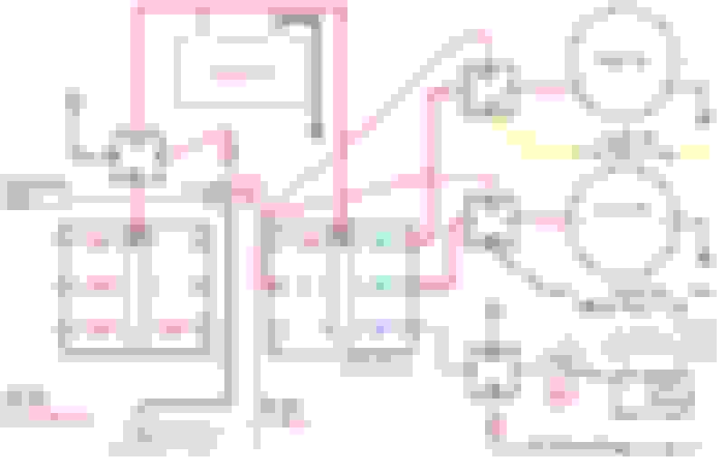
Part of my approach came from the attached diagram that I found on the web of a LS conversion on a Porsche 944. Things should not be that different??? I am just trying to get some input on my approach.
Part of my approach came from the attached diagram that I found on the web of a LS conversion on a Porsche 944. Things should not be that different??? I am just trying to get some input on my approach.
That diagram looks good except the modern LS PCMs (to my knowledge) output ground to trigger the relays. The fuel pump relay would not work as it shows ground as always connected. Give it fused 12V and let the PCM / computer provide the ground trigger to close the relay (just as shown in the high and low speed fans circuitry).
So.... yes, I would just tap in to the fans that way vs. the convoluted method of trying to re-use the Porsche fan relays and triggering with other relays upstream or allowing the Porsche computer to do it.
In terms of making the connections to the fan wiring:
I'd either use a weather pack connector to connect, so you can remove the fan later or install a small busbar or isolated stud on which you can make the connections.
One more comment, the way I wired my (one speed) fan, I have the another parallel fan relay which powers the fan circuit based on AC system pressures. IE. Trinary switch. I connect my 12V+ leads from the two fan relays to a busbar (again, you could use an isolated stud if you prefer). Pictures worth 1k words!
So either AC system or PCM triggers the fan to come on.
look in the lower driver's side corner and you'll see the busbar on the shroud.
Here's the fan mounted.
I used this relay box for the two fan control (and headlight) circuits.
That diagram looks good except the modern LS PCMs (to my knowledge) output ground to trigger the relays. The fuel pump relay would not work as it shows ground as always connected. Give it fused 12V and let the PCM / computer provide the ground trigger to close the relay (just as shown in the high and low speed fans circuitry).
So.... yes, I would just tap in to the fans that way vs. the convoluted method of trying to re-use the Porsche fan relays and triggering with other relays upstream or allowing the Porsche computer to do it.
In terms of making the connections to the fan wiring:
I'd either use a weather pack connector to connect, so you can remove the fan later or install a small busbar or isolated stud on which you can make the connections.
Both my drawing and the 944 drawing show the LS ECM as (-) and that is correct, right??? I think the LS944 diagram should state (-) signal from GM ECM, not (-) to GM ECM?? As for the fuel pump side, I was not going to use this 944 wiring diagram. I will just leave the Porsche relay in place and let the Porsche system turn it on and off.
One more comment... that little relay box, which is all sealed has fused, mini-relays came all pre-wired from the back side for $80 or $100 with the relays installed. The relays are about 1" x 1/2"x3/4" high.
Everything you show in the circuit diagram could be housed in that little box (plus two extra relay circuits). The box is probably 6" long by 2" wide by 2" high.
I installed mine in the driver's fender well to be near to the fan and the headlights.
Perhaps a better way to do it would be to just intercept Porsche's ground triggers from its PCM and trigger those with your own ground triggers. The relays should be easy to find from a wiring diagram. With ignition on, you can check for 12V+ at terminal 85 or 86 (which are the trigger terminals). The ground trigger should come from the Porsche computer (PCM). You could just de-pin that wire from the back side and pin-in your own.
Just a thought. And hope it helps you!
Doug
This is what I was trying to show in this drawing that I put together.
I'm following your drawing. Step 1 and Step 2 just refer to low and high speeds. It looks good. Are the OEM Porsche fans both two speed, then?
Are there AC condensers on both sides? If so, I might suggest either:
1. adding a third set of relays to run the fan when the trinary switch triggers the fans based on system pressures.
OR
2. The LS PCM also has a ground input from the AC pressure switch which can be used to to let the PCM know of the need for air flow over the condensers. Given the need for two fans and multiple relays, I'd probably suggest wiring and programming for to use the AC pressure input ground to your PCM.
Assuming 2001 is the same as 1999 996, the relays are in the driver's footwell panel #20 and #22.
Looks like his adding a manual switch should be just about as easy as adding the ground triggers from the GM PCM for low and high speeds.
I noticed in further reading of that reenlist thread that the low speed comes from running a large ballast resistor in series with the fan to lower the voltage. In my view, that's a **** poor way of getting low speed out of a fan. I have a similar setup on my 1992 500E Mercedes. The resistors are known to fail and add heat in localized spots (they turn red like a toaster element). Given that info, I might just use high speed only.
OR
If you wanted to do something really trick, you could use the PWM fan controller and wire it in lieu of the two low and high speed relays. Then you could enable the PWM functionality in the controller. (PWM - pulse width modulation) allows variable speed control of the fan. I read a thread recently where someone is using the one from a Chrysler mini van (I think). I suspect one would suffice for running your two small fans. They are good for something like 40 amps if I remember.
Hope that helps! And I'm not senselessly filling up your build thread.
Assuming 2001 is the same as 1999 996, the relays are in the driver's footwell panel #20 and #22.
Looks like his adding a manual switch should be just about as easy as adding the ground triggers from the GM PCM for low and high speeds.
Doug,
That is the same forum post that I was reading that gave me the idea. Yes, I agree that the way the Porsche system is getting the low speed is stupid. This is why I posted this idea up here to see if someone else thought it would work!!! And yes, i planned to use a GM pressure switch and let the GM ECM control the fans for AC condenser cooling as well.
If it were me, I'd probably just use the programmer to eliminate the high and low speed functionality from the fans. By setting temps properly, you can just skip right to high speed without using the ballast resistors.
And just have the trinary switch turn on high speed, too. Call it a day.
I have a large 16", 23 amp one speed fan. It is not loud inside my truck. Only from the front. The exhaust rumble drowns out the fan noise. with some tunes on, I cannot hear the fan at all. I have lots of dynamat, ceramic / heat sound deadening, carpet pad and carpet.
Doug
Doug,
Great stuff on the PWM's, LS1tech rocks for finding tech knowledge!!! After reading, these posts I will need to change the fan control setting in the tune of my E38 ECM to run the Porsche PWM system, most likely?
Doug,
Great stuff on the PWM's, LS1tech rocks for finding tech knowledge!!! After reading, these posts I will need to change the fan control setting in the tune of my E38 ECM to run the Porsche PWM system, most likely?
Yes, it is my understanding PWM control of the fan would need to be enabled. But, if you are working with a tuner, I suspect they could do that in an honest 5 minutes.
I saw Cunningham's Ryne Cunningham adjust my fan temp settings in less than 5 minutes after my tuning had been completed. He took his laptop out, plugged it in and the whole thing probably took 2 minutes.
In short, I'd suspect whoever tuned would do this for free or nominal + any shipping costs.
BTW - Porsche doesn't use a PWM system -> they used the lowly ballast resistor for low speed.
You'd buy that Chrysler PWM fan control module. There be five wires:
1. ground in, 2. positive in to the PWM controller, 3. PWM control in (from E38), 4. positive out to the fan. I believe fan would have its 5. own ground (vs. coming from the PWM control module).
The module would replace (or circumvent) any of the relays.
Doug
So no re-programming of ECM for PWM control needed, if I run the stock Porsche system? Only if I was to switch to the GM or Chrysler PWM system, right?
No. Porsche ECM is not compatible with PWM. That feature is only available for GM PCMs.
Basically, you'd abandon the Porsche control for the fans and use the E38 (GM PCM) with the PWM controller.
I can't speak to setup on the Porsche fan control via Porsche ECM. If it was me, I'd let the E38 LS controller control the fans given it is collecting the data.
If you want, PM me your # and we can talk live. Might be easier.
cheers,
Doug

 04-30-2015, 12:09 PM