When you click on links to various merchants on this site and make a purchase, this can result in this site earning a commission. Affiliate programs and affiliations include, but are not limited to, the eBay Partner Network.
I've searched and read plenty of the material on this, but I am still having a hard time understanding if I need to change anything with my set up. I am using 00' C5 LS1 with F-Body style engine harness and ECU. My charging system dummy light on the dash is constantly staying on from the moment I turn they key to ACC position. At first, I thought that the alternator was sending a signal telling me that it's bad, but further research confused me beyond recovery on my own haha.
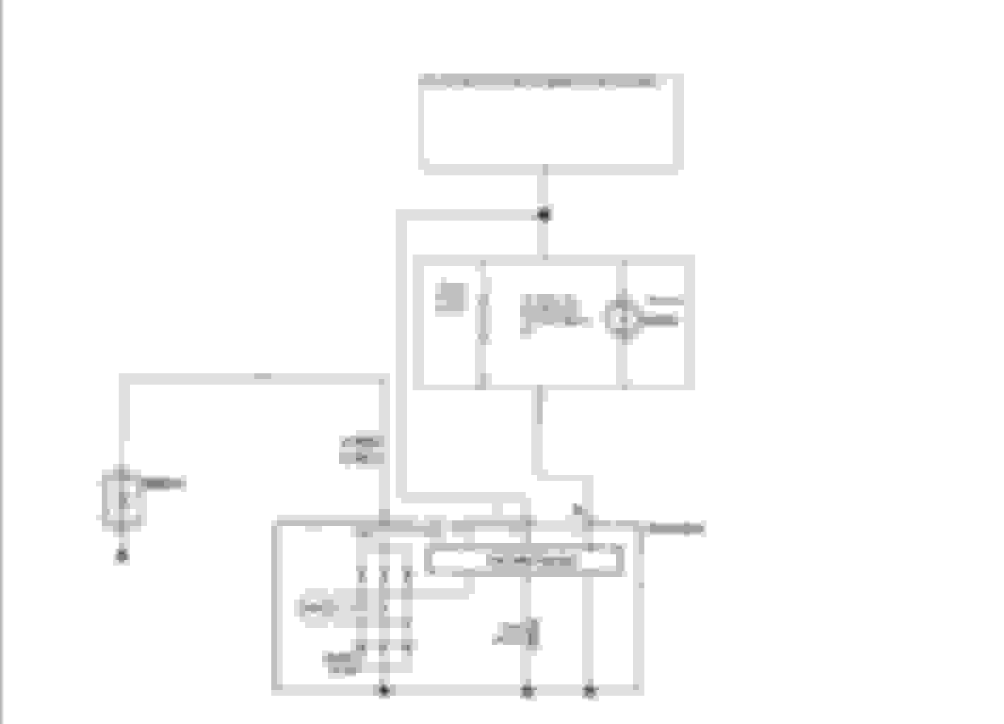
Here is what I am using as a reference:
1) According to the diagram, my dash dummy light will stay on no matter what as long as it's provided ACC and plugged in to the alternator which is proving the ground. I don't get it, is the alternator light suppose to stay on on GM cars?
2) According to some other threads, I only need to use that one (L) wire in order for my alternator to function properly. Than why does OEM Corvette harness use three if all you need is one?
3) If I unplug alternator plug all together, the annoying dummy light turns off of course, but it does not affect alternator operation. With or without the plug, the alternator does what it wants to. Some days it charges at 14.5V, and others it will drop to 13.2V (regardless of how much load I put on my charging system). But I am reading that apparently C5 alternator is adjusting to whatever the ECU is telling it charge at.. So 13V can actually be normal on a C5.
This is my first GM engine swap experience so I am hoping someone can shed some light on my "problem".
I can probably answer this for you, but I have to look at my truck. I promise, I will try to remember this, but if I don't answer in 2 days at most, feel free to pm me, and post a link to this, and then I will remember. I can explain what wires go where to get the dummy light off, and I don't know about the 13v deal, but I DO have a charging issue with my lights and stereo on at night. I think my gauge hits 11.5-12v, something I need to correct 1 way or another.
I can probably answer this for you, but I have to look at my truck. I promise, I will try to remember this, but if I don't answer in 2 days at most, feel free to pm me, and post a link to this, and then I will remember. I can explain what wires go where to get the dummy light off, and I don't know about the 13v deal, but I DO have a charging issue with my lights and stereo on at night. I think my gauge hits 11.5-12v, something I need to correct 1 way or another.
So far I've been driving around without any issues. Made it from San Diego to San Francisco without any drop in voltage (Charged at about 13.9-14.2V). But the light is still on. Show me what your set up looks like when you get a chance.
Was anything found about this? I'm having the same issue with voltage not staying constant, even when I remove the PCM from the equation and put 12 volts straight to "Generator Turn On Signal". I also noticed it acts the same even if unplugged (as the original poster said his was doing).
Yup, That's how I have mine wired, but the voltage ranges from 13v to 14.5v - and it also does this even if the connector is unplugged! Very strange. Seems like if I unplug the connector, it should not be outputting a voltage charge, but it is
"L" terminal to green 15. "F" terminal to green 75. The "S" terminal gets wired to the power junction block. Should b 16 awg with 20 awg fusibe link.
Don't forget aLos that the big power wire also gets run to the junction block too.
Also - why does the 12volt signal have to be ignition on? Why can't it just be a 12 volt (plus resistor) wire from the battery?
Internally the "L" pin is a ground with the alternator "off", this allows the lamp to light. When the alternator spins up, the the "L" terminal produces voltage which turns off the lamp by virtue of 12v -> 12v (no ground), thus no current flow. If you wire it direct to full hot, you'll kill the battery PDQ.
hate to bump an old thread but also looking for how this should be wired up. Just ordered the piece last night, trying to make it work on a 98 vette with a 99 up harness repin an 02 pcm, and an 02 alternator.

 05-06-2016, 07:40 PM