When you click on links to various merchants on this site and make a purchase, this can result in this site earning a commission. Affiliate programs and affiliations include, but are not limited to, the eBay Partner Network.
1970 Chevelle Turbo LQ4 Build – From Start to Finish
Car Specs
1970 Chevelle
2005 6.0 LQ4 – unknown miles
o Texas Speed Cam/kit - 232/240 .595/.609 115LSA
Chromemoly push rods
PRC .650” dual springs
o FIC Injectors – Bosch 650 CC (82.5 lbs/hr)
o Walbro 255 external pump
o LS9 Head Gaskets
o ARP head bolts
o Melling high pressure oil pump
o LS2 timing chain
o LS2 intake
o LS6 Accessories
o Tuned by me (HPTuners)
2005 4L80E (stock internals)
o Circle D converter, approx. 3k stall
3.33 Gears
Turbo Setup (on a budget)
69mm 1.05ar VS Racing Turbo
CX Racing Intercooler
2.5” intercooler piping kit
VS Racing 44mm Wastegate
VS Racing 50mm BOV
2.5” hot pipes (aluminized mild steel)
4” downpipe (aluminized mild steel)
Truck manifolds facing forward
2 Flex couplings for each hot side (since this is a frame mounted turbo)
NGK TR6 spark plugs gapped to .025
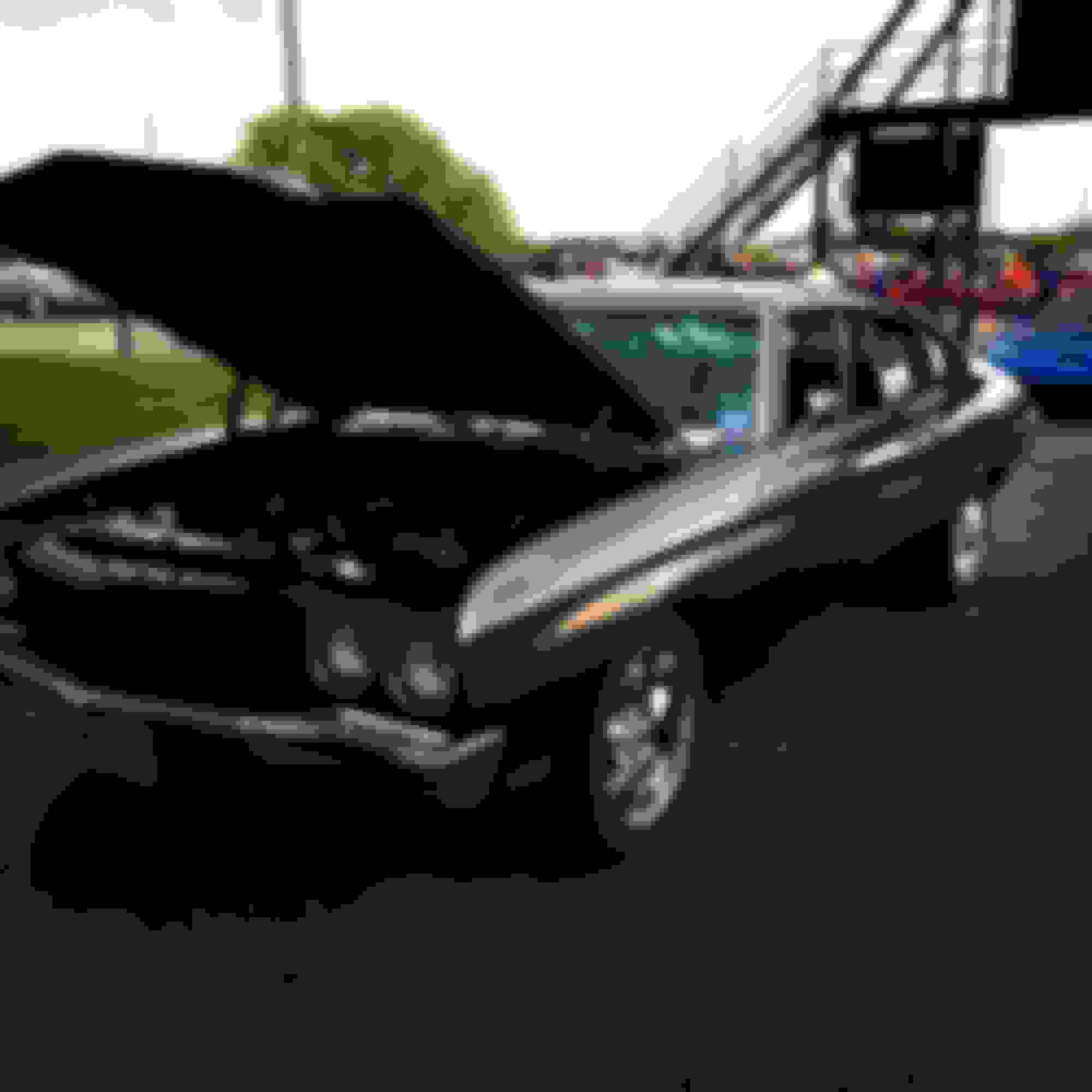
Below is a pic of my original setup
TURBO LOCATION/BRACE – FRAME MOUNTED
I have a Vintage Air system, which puts the A/C compressor in the best location for a turbo.. So I moved the battery to the trunk, and created a turbo mount to place the turbo behind the passenger side headlight. The brace mounts to 4 areas of the frame. It was built using 3/8” and ˝” bar stock.
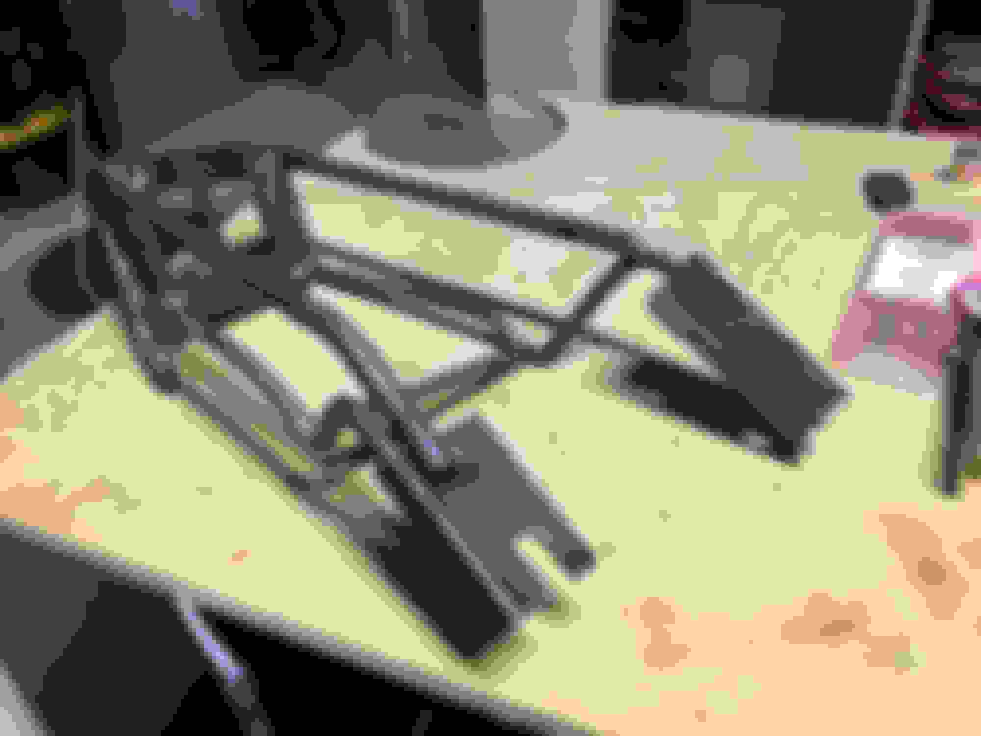
Below is a pic of the frame mounted turbo brace I made. I added two extra mounting points to this, which aren’t shown in this pic.
Here is a pic of the mount installed on the car (you can see the two additional mounting points here – on top of the frame). There is an A/C line in this pic that is close to the flange, but it shouldn’t be close enough to melt. I plan to move this A/C line to under the brace in the future.
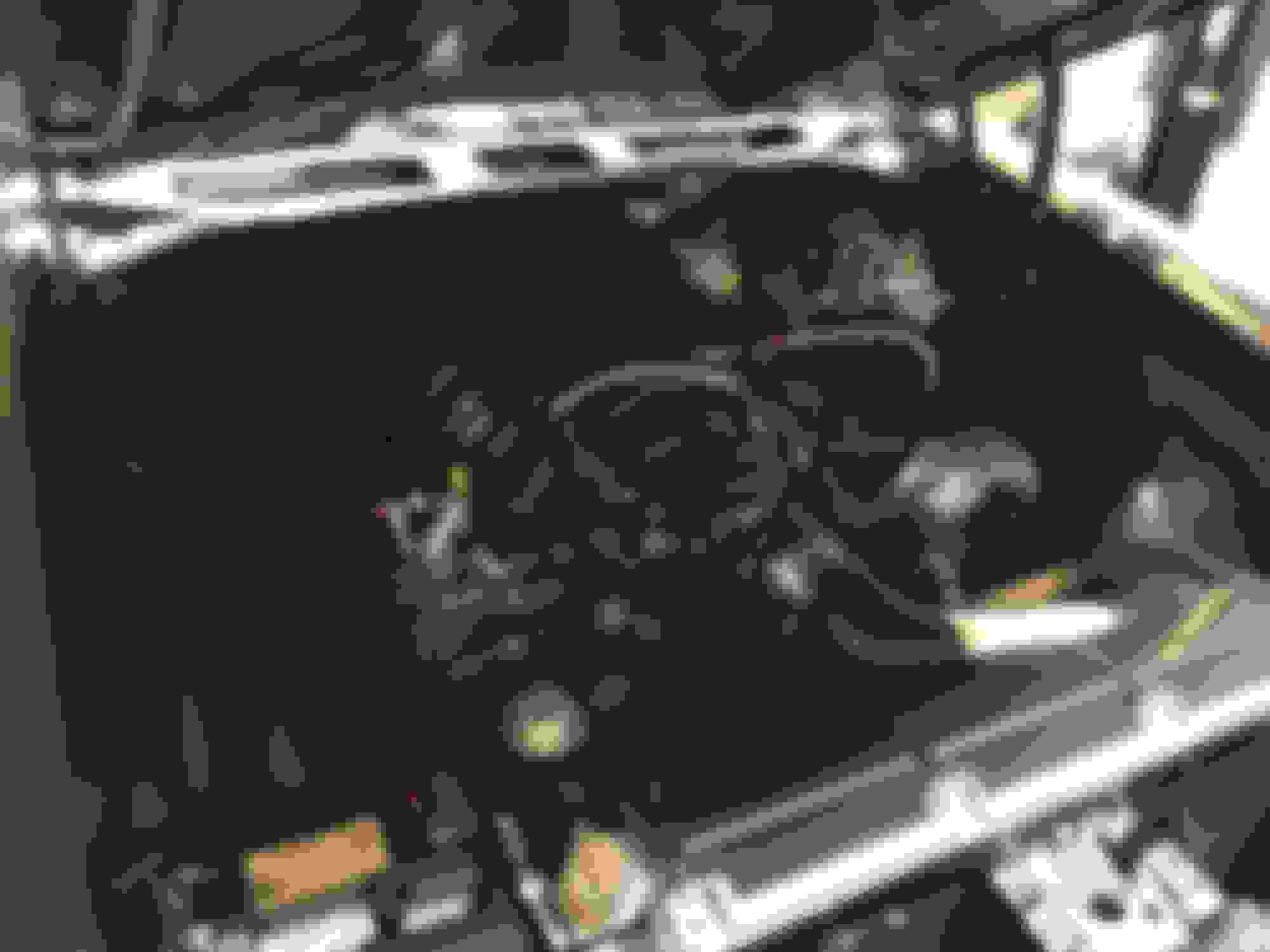
Picture of how the turbo will sit in the car
Tight fit with the hood closed. I got lucky; there is a hump under the hood right where the turbo is
HOT PIPES/MERGE PIPE/MANIFOLDS
Next up was the merge pipe. I made this on my own after seeing people having problems using standard Y-pipes to merge their hot pipes together. This is welded to the T4 flange. This should flow pretty well.
Here is an undershot of the merge pipe welded to the turbo brace/flange. Just enough room around the hoses/fans that it shouldn’t melt anything once wrapped. Protection will be added to the radiator hose, just in case.
I then moved to tweaking the exhaust manifolds to fit facing forward. First was the driver’s side. I needed the outlet to come out right under the power steering pump. It ended up working perfectly; after a lot of cutting and welding, of course.
Here is an undershot of where the outlet ended up initially on the driver’s side.
Added some more pipe to the manifold to get it closer to the front of the engine.
I then added a V-band clamp. Tight fit, but it will work. It is a clear shot to the front of the engine now, and over to the merge pipe.
I then moved onto the passenger side manifold. I used a stock truck manifold for this side also. I had to cut the original flange off, but it fit a lot better than the driver’s side. A slight bend was needed, which I welded a V-band to.
Now that the manifolds were mocked up, I started work on the hot pipes. I didn’t take any progress pics, but here are some pictures after I had everything tacked up.
Wastegate placement took a while for me to figure out. I ended up cutting a section of a 1.75” U-bend and merging it into the passenger side pipe, right where the pipe turns to go into the merge collector. This should allow exhaust to easily flow out of the system and prevent boost creep.
There are some gaps in this pic, which will be covered up using filler metal. Not bad for eyeballing/hand cutting it though.
I got pretty good at welding V-band flanges
All the pipes and brace welded up and ready for paint
DOWNPIPE/EXHAUST
I moved onto the downpipe next. This will be wrapped in Titanium exhaust wrap, once I get the wastegate pipe fitted onto it. Originally there was an A/C line that was routed next to the A/C compressor; I moved this to behind the compressor. The original location of the hose was too close for comfort.
In this picture a plug wire is touching the pipe. The final fitment will leave a small gap between the plug wire and down pipe. I plan to protect the wire from the heat.
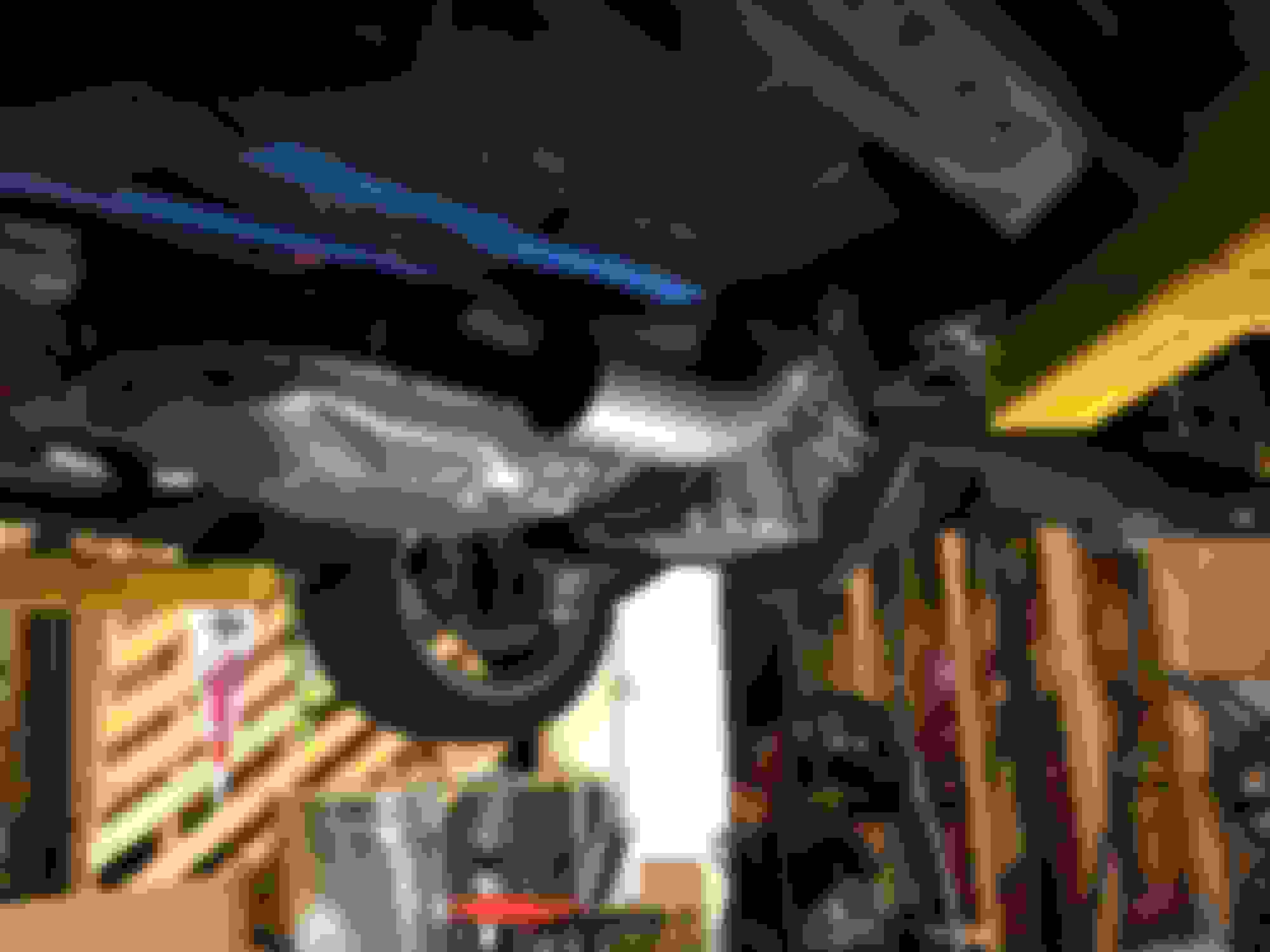
Here is where the pipe ends up under the car.
Here is how I am routing the wastegate exhaust flow into the downpipe.
I picked up a used 4” in/out muffler for $30. The muffler is huge. It ends up about 5” from the rear axle. I plan on getting a more compact muffler in the future, and route my exhaust around the axle and exit right behind the Passenger side tire.
INTERCOOLER
One of my main issues was the intercooler fitment. This was another issue caused by the Vintage Air system, this time the A/C dryer. I was originally going to go with a small intercooler (a tiny 12” x 12”), but decided to order some aluminum tubes and make my own AC lines to move the dryer. This ended up working perfectly.
Picture of the original dryer location
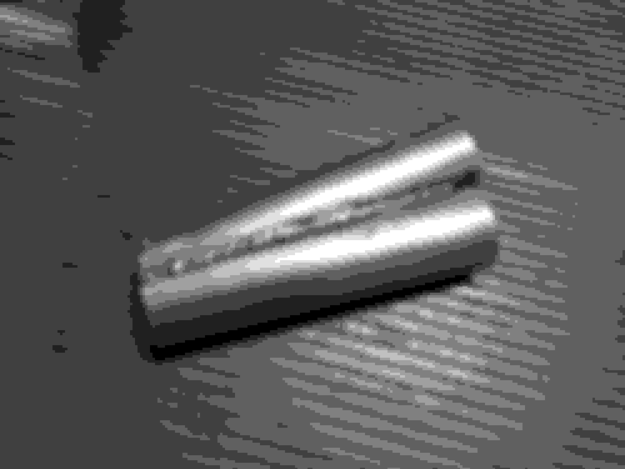
One of the new lines I bent to move the dryer out of the way
New dryer location
Intercooler fitment required cutting the front grille brace and removing the factory hood latch assembly. I also had to cut the inside of the grille a few inches on each side in order for the intercooler to fit.
Once the intercooler could fit behind the grill, I used the factory hood latch support as a mounting point. I used a flat metal bar to connect the intercooler to this support.
The intercooler brace after paint.
Routing the intercooler piping wasn’t the easiest job. Initially I was going to route the pipes through the wheel wells, but the pipes ended up hitting the turn signal housings on the bumper. The only option was to cut holes between the headlights and radiator and feed the pipes through there. If you are wondering why I didn’t go with an intercooler that had side exit ports, it is because of the A/C dryer. The Passenger side exit would hit the dryer if it was located on the side and not the bottom of the intercooler. If it wasn’t for the dryer, the intercooler routing would have been much more simplified. The Driver’s side could have had a side exit – I may have this intercooler modified later on, but for now, this will do.
I had to route the piping above the frame, as going below the frame would have made the pipes visible, even with the bumper on the car. You can also see the hood pins I added, in this pic.
I then used a 2.5” to 4” adapter to connect the intercooler piping to the MAF/Intake. I did this to give the MAF a better opportunity to measure the air flowing to it; without the air coming straight from a small pipe.
OIL SUPPLY/DRAIN
For the oil supply I used about 5 feet of -4AN braided steel hose, connected to an adapter plate above the oil filter. The oil supply fitting I ordered for the turbo did not fit, so I just tapped the oil supply port on the turbo to match the thread of the 90 degree fitting I used.
For the oil drain, I used an oil return flange with a 5/8” hose fitting. I then connected about 2.5 feet of hose, which routes under the turbo brace and to the front timing cover. At the front timing cover, I drilled/tapped a hole to accept another 5/8” fitting (1/2” MPT), which is where the oil drains to the pan. Note: After getting everything finished and driving the car around, the rubber hose started to make contact with the turbo brace, which the heat eventually started breaking down the rubber hose. I replaced the first couple inches of rubber hose with a metal pipe.
Yellow dotted line shows where the hose runs under the merge pipe
Here is a picture of the hose draining into the timing cover. I ran the engine with this disconnected, and the return flow is good. I will protect this hose from the exhaust.
GAUGES
I’ll be running boost/fuel pressure/wideband gauges. My Chevelle has a “racecar” interior, but it also has a roll cage. I designed a roll cage gauge pod, which matches the angle of my roll cage (45 degrees). I will make 3 of these and have them stacked on the roll bar.
1st 3D print of the gauge pod
Gauges installed (missing the fuel pressure gauge). I plan to run the wires in a nice loom and zip tied down the roll bar.
Previous owner removed the interior, so don’t laugh at my ‘racecar’ dash.
FINAL INSTALLATION PICTURES AND VIDEOS
Short video of my first startup – this is with an open downpipe
More videos to come. I'm running it at 7 psi right now. I have only tuned it to about 40% throttle. I am currently waiting on my fuel pressure gauge, once I have that, I can tune it to WOT.
Where did you mount the computer and relays/fuses? I have vintage air and installed it myself while shaving the firewall and mounting everything behind the firewall for the old school 350. I'm now doing a 6.0 ls swap and want to keep everything clean and functional. Just trying to get some ideas. Car sounds and looks great!!!
My '69 Chevelle turbo 5.3 is setup almost exactly like yours! Holley a/c, same manifolds, similar routing, etc! Great job
BTW- you nee waaaay more fuel pump than what you are running. Nice looking Chevelle!
I plan to keep it around 500 rwhp for now, which the pump should handle. I agree though, which is why I am waiting for the fuel pressure gauge before tuning it any further. Nice Chevelle, I almost went A2W on mine also! haha
Where did you mount the computer and relays/fuses? I have vintage air and installed it myself while shaving the firewall and mounting everything behind the firewall for the old school 350. I'm now doing a 6.0 ls swap and want to keep everything clean and functional. Just trying to get some ideas. Car sounds and looks great!!!
Thanks!!
Unfortunately, I can't provide much advice in the PCM location, because I do not have a standard interior. My dash is just a piece of flattened sheet metal. I keep my PCM mounted under the "dash", right above where the vintage air is mounted.
Cool build-did you use the Holley oil pan? I have the GM Hot Rod pan in my 65 A body, switching to the Holley pan this winter
My turbo drain right now is just below the balancer, I will have to relocate it to somewhere, seems like a lot of guys are using the front cover
I want to lower the engine in hopes of fitting an 80E in
Yup, I have the Holley pan. I ended up drilling/tapping the timing cover, as there is barely any space on the front of the oil pan (or front sides of the pan)
Sweet car man, too bad about the dash. Your car is like the complete opposite of my Chevelle....the interior of mine is the only "stock" appearing part.
I cannot get the truck manifolds to fit like that at all. They hit all kinds of ****. I may have to raise my motor in order to use stock manifolds. I didnt use swap style mounts, I made my own, and set the motor at 3*up in the front. I guess I could always make my own stainless log manifolds.

 11-28-2016, 11:27 AM