When you click on links to various merchants on this site and make a purchase, this can result in this site earning a commission. Affiliate programs and affiliations include, but are not limited to, the eBay Partner Network.
Every time I go to the Junkyard, most of the 1st gen Libertys are missing a head or 2. lol...But when they were new, those 3.7's in such a small truck were good at getting up the icy hill (30ish degree incline) into the detail bay. lol
I was working on trying to re-purpose or remap a 2010 Camaro center 4 gauge cluster (oil pressure, oil temp, volts, and trans temp) into my 68 Camaro. My plan was to run (oil pressure, water temp, fuel level and volts like factory center console car) I don't want to input from the canbus I want to output to it like like factory by converting resistance or 0-5 volts etc. from a temp sensor, a oil pressure sender, tank fuel 0-90 ohm sender. So basically I am looking for 4 inputs they way you did fuel and a canbus output to the pack of gauges. Then I would just have a set of face plates made to cover the factory units and have a new console with working gauges of my choosing. These center console gauges are relatively plentiful and could then be re-purposed for any configuration with the correct scaling and sending units. I have done some searching, but didn't find anyone who sniffed out the factory values to run these gauges.
These guys can make the faces for you. https://www.blackcatcustom.com/ Paid about $150 since I had to pay for them making the setup and it did include the overlays. Now that it has been made it the cost should only be around $50-60 for the overlays alone. I made my own setup using the motors from a 95 Camaro cluster and a 97 Tahoe cluster. I had them calibrate the overlays to the Camaro scale but if I had to do it again I would calibrate it to the Tahoe scale. The motors on the Tahoe are self contained and the you can use the senders from the Tahoe connected directly to the back of the gauge. The fuel sender for the Tahoe is in the 0-90 ohm range so that will work as well.
It's been a while since I posted anything here so I figured it was time for an update. Here is my "Proof of Concept" for converting HS Can data to much......MUCH slower formats with out flooding the data bus.
HS Can is 500 Kbps
J1850VPW is 10.4 Kbps
That's a HUGE difference in speed and the amount of data being processed. It's taken some time and I only have a couple of gauges working......WAIT...WHAT????
What is this converter actually gonna be, a little box between CAN lines? You're ideas and work are giving me hope of transplanting a late 6.4L Hemi into my '98 Dakota. The DAK's bus is CCD, the Hemi is much faster. It would be even more awesome awesome to translate the CAN line from an aftermarket PCM (Holley) into something that would drive the rest of the vehicle's bus!
What is this converter actually gonna be, a little box between CAN lines? You're ideas and work are giving me hope of transplanting a late 6.4L Hemi into my '98 Dakota. The DAK's bus is CCD, the Hemi is much faster. It would be even more awesome awesome to translate the CAN line from an aftermarket PCM (Holley) into something that would drive the rest of the vehicle's bus!
This is where time and access to things become the limiting factor. What your suggesting is absolutely... 100% possible... however the likely hood it will ever happen is almost non existent unless you do it your self and unless you have an enormous amount of time and are very good with electronics and can learn how to program.... and also are able to reverse engineer a data bus with no documentations then there is very little hope you could do it your self.
I have been considering the idea of a job/career change over the last several months to pursue things similar to what I have been doing in this thread because the possibility's for this type of technology have never been realized. Some of my designs that are unpublished are likely going to become necessary in the coming years with the changes in vehicles/computers to make even basic modification possible on new vehicles. However this is a catch 22.... the only way I will ever have the time to perfect my designs and create new one's is to make a career out of this.....but the only reason I have gotten as far along with my work as I have is because I've been able to sink an enormous amount of money into what I'm doing because I have a job that pays well and a wife who understands the potential impact of what I'm working on.
It's hard to gauge potential demand for a technology that doesn't exist.
I would look at the most common swaps that have difficulties with factory gauges like you alluded to with the Jeep swaps. And another one would be the 94-04 Mustang's swapping LS motors. Most end up running their stock ecu along side the LS ECU to try and keep the factory gauges. Would certainly eliminate lots of confusion and wiring. Keep up the great work. Lots of potential here.
I would look at the most common swaps that have difficulties with factory gauges like you alluded to with the Jeep swaps. And another one would be the 94-04 Mustang's swapping LS motors. Most end up running their stock ecu along side the LS ECU to try and keep the factory gauges. Would certainly eliminate lots of confusion and wiring. Keep up the great work. Lots of potential here.
The first version of this I'm setting up is for 4th and possibly 5th gen engine swaps into Non-CAN Gm vehicles. For trucks it would be 96-07 and Car's would be something like 96-04 or around that time frame.
I now have analog Speedo and Tach signals working, I'm waiting on a batch of circuit boards so I can test this in a running vehicle to make sure the gauges are smooth and do not lag but I'm pretty confidant they will work. I'm incorporating J-1850 VPW and Analog gauge support for Speed, tach, Temp and Oil pressure simultaneously to reduce the number of possible variations. I'm also working on incorporating some type of DIPSWITCH setting to switch between 2,4,6 and 8 cylinder tach settings. The trucks will benefit from this the most, the 96-98 trucks read differently then the 99+ trucks. Sure this can be done in the tune with the tach pulse setting....or I can do it with a simple equation using 2 input pins just as easy.
I have a Jeep in my garage that's about to get a heart transplant so I can start working on getting something going for 3rd,4th and 5th gen LS pcm's to talk to the Jeeps data bus.
Getting close every day.....I now have CAN to Analog conversion working. Speedo, Tach and Temp are using mode 1 data pids so the CAN side is pretty universal. This is going to be a god-send when people start getting into LT swaps and are not able to pull Speed and Tach signals off a wire from the PCM anymore.
Hadn't thought of it that way but that's probably pretty accurate lol. Clusters are what I'm currently working with because they are easy to get(for the most part) but are only a small part of my work and really doesn't begin to cover what my end game would be capable of.
I have a couple of other projects that involve data conversion/manipulation that solves some of the major issues people are running into right now but I lack access to the parts and vehicles these parts would be found in for the needed data acquisition and testing. I can only do so much on a bench although I'm putting together some goodies to make bench testing some aspects possible.
I hadn't planned on tipping my hand on some of the other potential modules I've planned out but there are only so many hours in the day and my resources are limited.
1) module to intercept and change the vin number on the newer transmissions to match the PCM when a used transmission is installed(Talking 2015+). The vin is a one time deal, once it's flashed your not able to change(even with SPS) it making it impossible to use the transmission with out module replacement that involves transmission disassembly....and forget about useing those transmissions with older types of Pcm's.
2) It's taken years to get the 6l90 to work in swaps and even then it's limited to working with a couple of specific type of Pcm's. Throw everything any one has ever said out the window, it is absolutely possible to make the 6,8 and even 10 speed transmissions work on 3rd gen Pcm's, the module to do it just doesn't exist yet.
Those are just the tip of the iceberg to give you an idea of what else is possible.
A lot of people would LOVE to have a 6l90 or beyond paired up easily to the "older" PCM's. That would practically be a guaranteed success right there.
There may come a point that I just gamble on all of this and have faith that there is a market. At my current rate things like a 6l90E converter is so far down the line I wouldn't even guess at a time frame......doing this type of work as a full time job it could probably be ready for in vehicle testing with in a couple of months.....but it's just a nice "What If" thought we all have from time to time.
I have a T42 controller for a 4l65 on my bench I have been looking at for a couple of months now and my daily driver has a 4l60 in it so it's something I have the tools to test.... but I'm lacking a great portion of the data to even try and get it working at this point. So many projects and so little time.....I only get around 6-8 hours a night to work on this stuff and lately it just isn't enough
2) It's taken years to get the 6l90 to work in swaps and even then it's limited to working with a couple of specific type of Pcm's. Throw everything any one has ever said out the window, it is absolutely possible to make the 6,8 and even 10 speed transmissions work on 3rd gen Pcm's, the module to do it just doesn't exist yet.
This would be amazing, dropping a 6l90e into a 00-06 3/4 8.1 suburban is a dream of mine.
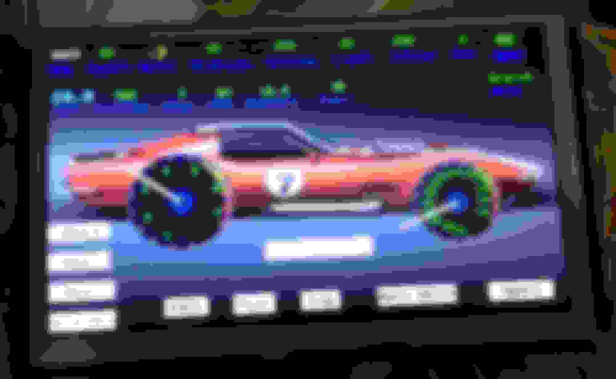
Here's another idea for you. I've done this for my 1976 turbo LS Corvette project. You can easily add another display option for your Arduino boards with little or no changes, just a serial port. I customized this arduino / CAN BUS (not a GM CAN BUS) display for my Vette. Part of my DIY 4l80E transmission controller. The display below is on a workbench, so data is being supplied by an arduino CAN BUS simulator I built for testing.
LMK if you want any additional info on this. The display unit is very easy to work with and fairly reasonable. Should be no problem for you.
I'm always open to free info. You can PM me anything relevant you'd be willing to share. I've done some tinkering with OLED displays before but the cost and connections would create a bit of an issue. I also found that most of the cheaper displays don't like the cold weather, had one crack in my vehicle this past winter. Not sure if it was from the temp of the display heating the glass too quick or the heater from the truck to did it but it wasn't pretty.
First I want to congratulate you for what you have achieved so far.
I�ve also been playing with an Arduino and sensor interfaces. No CAN bus though. I ended up making a custom board with the same Atmel processor as on the Arduino. I have some 0-15v analog inputs. Some 12v PWM controled outputs and som 5v I/O ports. I suspect I�m utilizing the same LCD as LSswap uses and did not experience problems during Norwegian winter. There are some glare when sun is bright.
As my 03 Chevy Silverado has started acting up I�m about to get started on a J1850VPW project myself. Waiting for delivery of a Macchina2 to start decode messages on the bus. My first goal would be to isolate the message and orgin of said message that makes my door modules turn on the mirror heat once in a while while when truck is parked.
Then it would be nice to decode as many PIDs as possible.
If you are willing to share anything you have learned it would be appreciated. I�m not quite sure how to start so if you have any forum post or documents containing good information please tell. I will of course share what I learn during my project with you. I only have a 03 Silverado and a spare gauge cluster to experiment on. Not so easy getting hold of parts here in Europe.
First I want to congratulate you for what you have achieved so far.
I�ve also been playing with an Arduino and sensor interfaces. No CAN bus though. I ended up making a custom board with the same Atmel processor as on the Arduino. I have some 0-15v analog inputs. Some 12v PWM controled outputs and som 5v I/O ports.
Thank you for the complement. I know a lot of what I have shared doesn't look like much to most people but it's also to keep a low profile on some of my work for the time being. I have used the ATmel chips in various forms and packages and in the end I end up doing a great deal of my work directly on an Arduino or mounting an Arduino to my Pcb's just due to the cost. I have looked at moving my work to the ArduinoDue/Macchina Arm platform more then once but there is just too much difference to make any of the code easy to port over. Neither platform is very well supported or documented and has a serious lack of library support making it less then ideal for much of my work.......I haven't run into bandwidth issues yet but it's going to happen sooner or later.
As my 03 Chevy Silverado has started acting up I�m about to get started on a J1850VPW project myself. Waiting for delivery of a Macchina2 to start decode messages on the bus. My first goal would be to isolate the message and origin of said message that makes my door modules turn on the mirror heat once in a while while when truck is parked.
I have both versions of the Macchina and honestly I wasn't all that impressed with it. I know one of the community developers over there and he lives about 30 minutes from me......one of these days maybe we'll sit down and try to hammer of some of the shortcomings of the device. I know the guy is writing an Elm library for it but it's not as easy as you might think to get it working like that.
As for your truck I think your going to be looking for something that isn't there with the heated mirrors. The J1850 data line is pretty limited on bandwidth and is limited to sending messages between computers for functionally rather then just sending out every thing happening the way CAN does it. I'd have to pull a wiring diagram but I'm suspecting your heated mirrors are not going to be on the data bus.
Then it would be nice to decode as many PIDs as possible.
Just to keep the context of this clear for others reading this, the information that's streamed on the data line technically are not data pids. A data pid is something that you send a request to a computer for and the computer will respond with an answer/value. In the case of the raw data stream messages are broken down by priority, destination and source followed by the actual data.
Here is an example....
E8 FF 60 03 98
E8 FF 10 03 B3
E8 FF 58 03 03
E8 FF 29 03 64
These are messages that are constantly sent onto the data bus by various modules as a way of saying I'm here still. To break down the message would go something like this. E8 is the priority of the message, FF is to all modules on the data bus and the 2rd byte is the module sending the state of health message. The 3th byte of message being 03 indicates that the module is present and functional. The last byte is the checksum and isn't something you need to pay attention to for what your doing.
An example of how modules talk to each other would look like this....
1) 8A EA 29 20 A7 00 30
2) AA EB 60 20 A7 00 E7
3) 8A EA 29 20 95 00 69
4) AA EB 60 20 95 00 BE
#1 is the ABS controller sending a message to module EA(Cluster in this case) with a priority of 8A. The actual message being sent contains 2 parts. The 3rd byte of 20 is the command for OFF, if it was being tuned on the byte value would be A0. The 4th and 5th bytes are the item that would be commanded On or Off, in this case A7 00 is the Brake Light . So if we reconstruct the message it would like this. The Abs controller is sending a message to the instrument cluster to turn off the brake light.
#2 is the response from the Cluster back to the ABS controller acknowledging the message was received and executed.
#3 is the exactly the same as message #1 but the item in the cluster being command(95 00) is now the ABS light being told to turn off.
#4 is the response the message #3
Now these are very easy example where what's going on is cut and dry. What makes this more difficult is that some messages will not have a response so tracking down the module receiving the data can be harder and that some messages are used by multiple modules but for different things. If you dig deeper and start sending commands and plugging in other modules the results will also change. If we use message #1 as an example, sending it from node 29(ABS) will only turn the brake like off for 2 seconds. If the message isn't sent again the light will come back on by default. If we reconstruct the message but send it from the Pcm (8A EA 10 20 A7 00 30) where 10 is the PCM node ID the brake like will be commanded off until the next time the ignition is turned off. The reason this is important is that the instrument cluster will no longer respond to a command from the ABS and send the response the ABS is looking for. By sending it from node 10 the cluster now thinks there is no ABS and will stop looking for a message. This should give you a general idea of what can happen when modules are sent data from the incorrect ID. This doesn't mean they all work like this but you need to check and recheck to make sure any data you send doesn't have an adverse affect that you might not be aware of at the time.
If you are willing to share anything you have learned it would be appreciated. I�m not quite sure how to start so if you have any forum post or documents containing good information please tell. I will of course share what I learn during my project with you. I only have a 03 Silverado and a spare gauge cluster to experiment on. Not so easy getting hold of parts here in Europe.
I've data mined the 03-07 clusters from the 1/2 ton and 3/4 ton trucks as well as the full size SUV's. There are some messages in the clusters that will make you laugh or start scratching your head. For example if you send the message 8A EA 10 A2 B4 00 you will get the message "REPLACE LIFT GATE FUSE". Some of those messages would be nice if they were to actually work........there are a lot of messages like this that are programmed into the cluster but that are not actually used for what ever reason.
And as always I'm open to information either publicly or by PM if you would like to share or have questions.
While this is not directly related to the topic of this discussion this is something I've been working on for the last couple of weeks. It's rather low tech compared to data bus conversion stuff but it's solving an issue that currently has no solution.
I can read either a tach signal or even spaced hall effect sensor and generate the crank signal output pattern that the vehicles OEM pcm is looking for. Right now I have the 4x, 24x, 58x and 36-2-2-2(Mazda) patterns working with this. Other application I'll be adding to this will include the Jeep 3.7 and 4.7....sure there is already a commercial device that does the same thing for the jeep pcm's but it's way over priced and I was able to cover a whole lot of other signal patterns with the same hardware so I figured why not.

 03-04-2018, 07:32 AM