
1978 Aerocoupe Caprice: 5.3 / 4L60E


 06-28-2018, 09:55 PM
#22
TECH Senior Member


 07-04-2018, 04:17 PM
#26
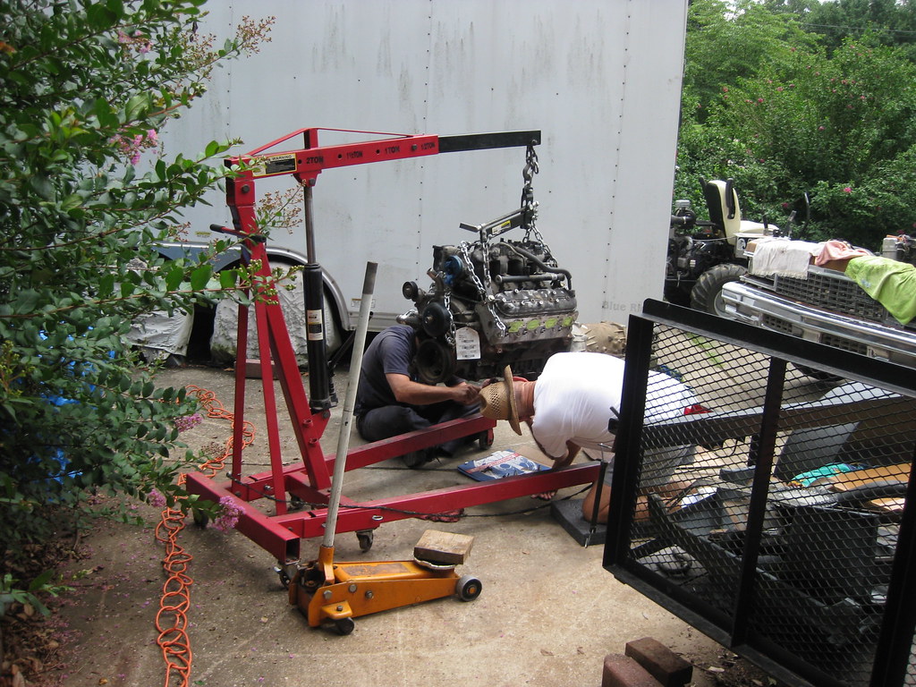
Looking at the pictures, it amazes me how much work can be summed up into so few pictures. The heat and mostly humidity has been so hot and for the most part I have had no shade to work in. Several years ago I had a couple instances of being severely overheated and since those times I am unable to bear excessive heat as I was once able. It's pretty inconvenient if nothing else.
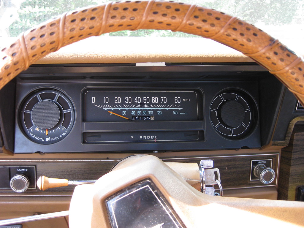
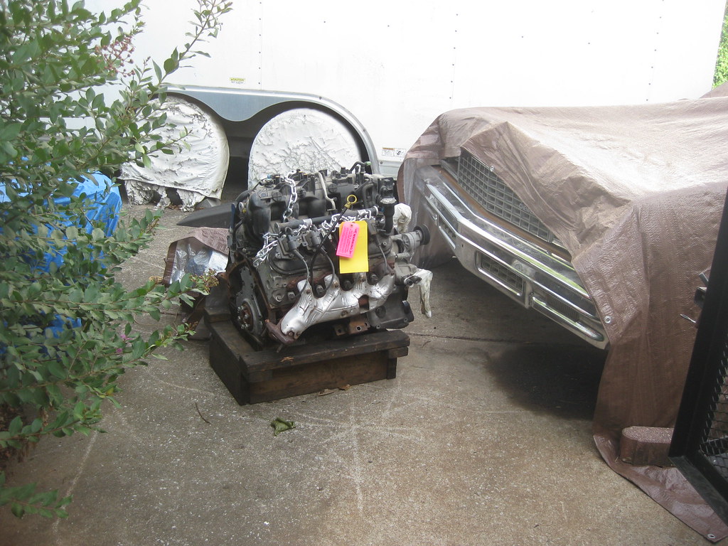
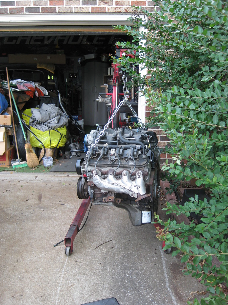
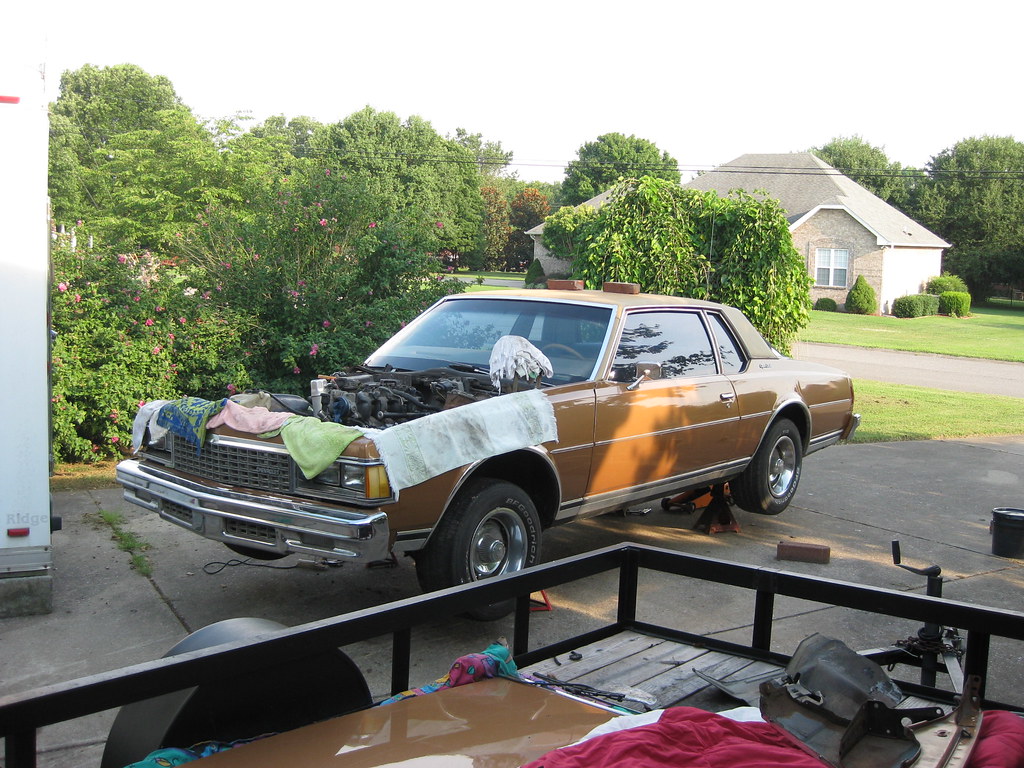
This is where the engine lived, placed by the tractor, protected by a tarp, until the new parts came in.
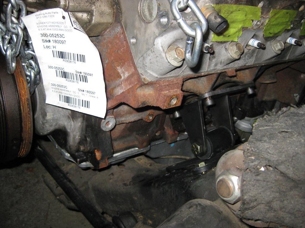
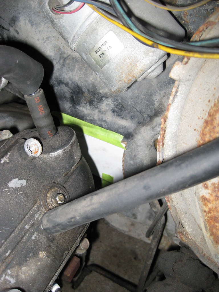
The BRP engine mounts did not fit as they were supposed to. I tried every combination of holes possible and there was nothing that would work. This picture shows how far off the bolt hole was.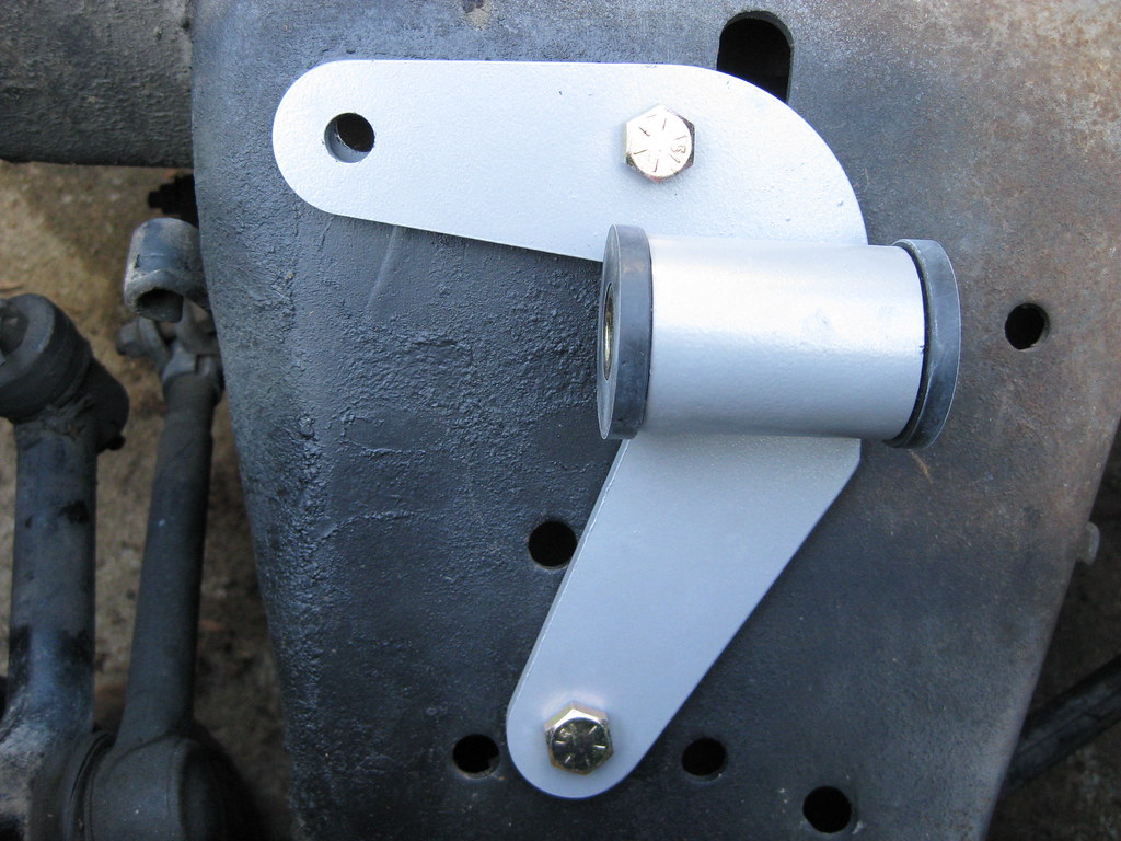
I was able to indicate with a marker from the backside where to drill for the motor mount. I called the company and they instructed me to install the engine and get the fitment to determine which top hole I should drill out. For the amount of money this kit cost, this should absolutely not happen.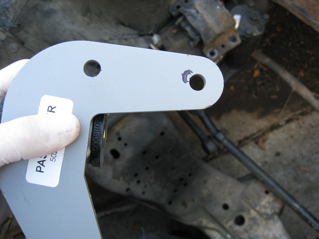
With off-set hole drilling like this, the drill press helps a lot.
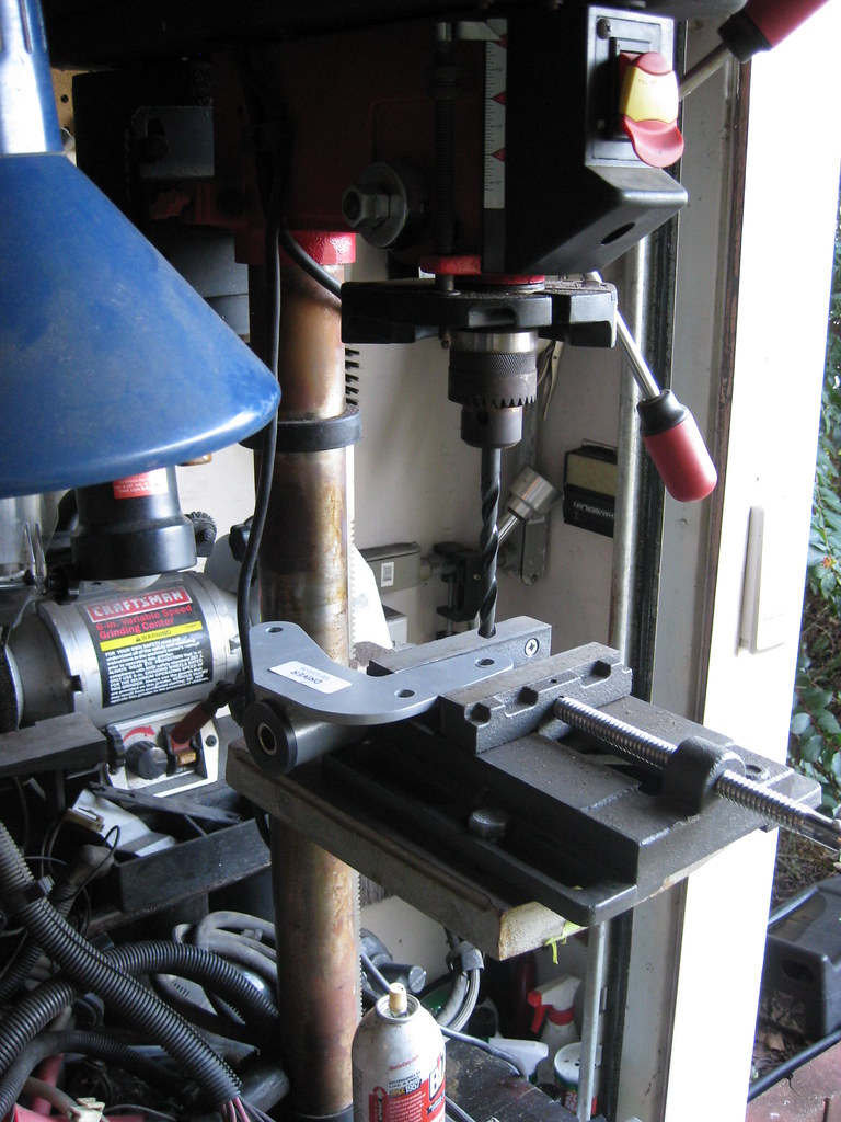
However, the drill press still can quite finish the job because of the way the new hole was offset inside the old hole. I have to use a file to get the finishing touches.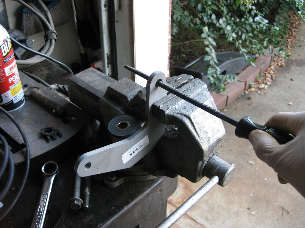
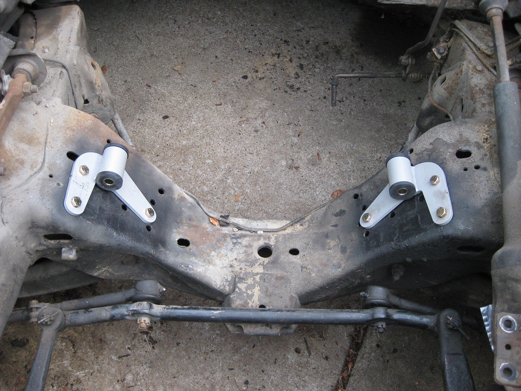
After quite a bit of work, they fit.
I drained the torque converter from the new transmission in anticipation of the installation.
I ordered a new oil pan from a 1998-2002 GM F-body. This would be a V8 Camaro Z-28 or Pontiac Trans Am. I also ordered a new gasket. If I only knew then what I know now.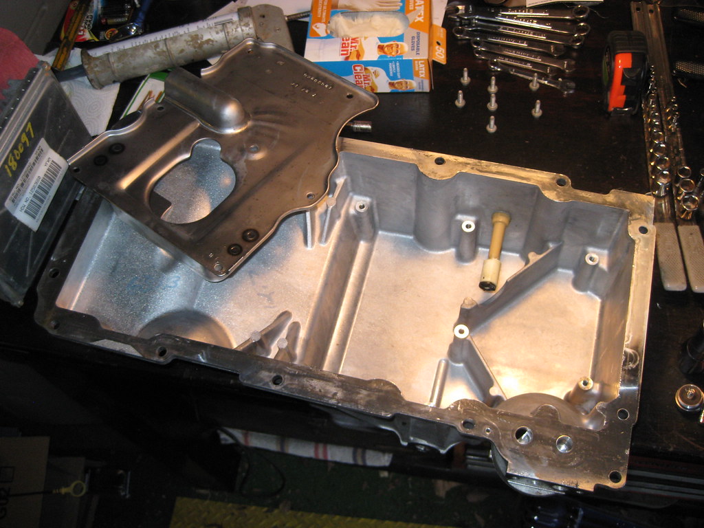
With the new oil pan in, I began removing some components off of the motor for installation.
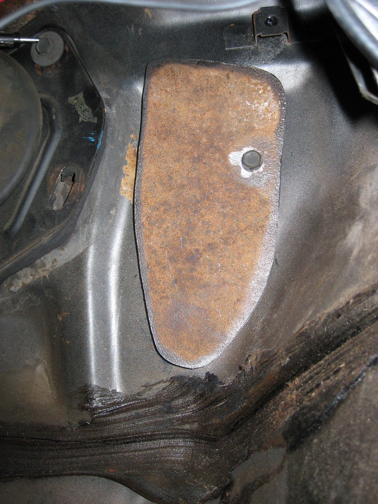
The old oil pan from the 5.3 sits much lower than the F-Body pans. This causes the bottom of the pan to sit too far below the frame of the car, leaving it vulnerable to damage and thus catastrophic engine failure.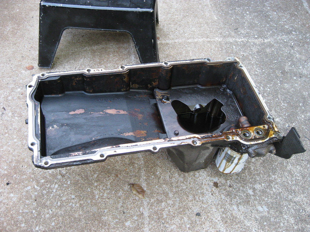
When I removed the exhaust manifolds I found that the rear driver side bolt was already broken off inside the block. That was unfortunate, but not entirely unexpected for an exhaust manifold bolt.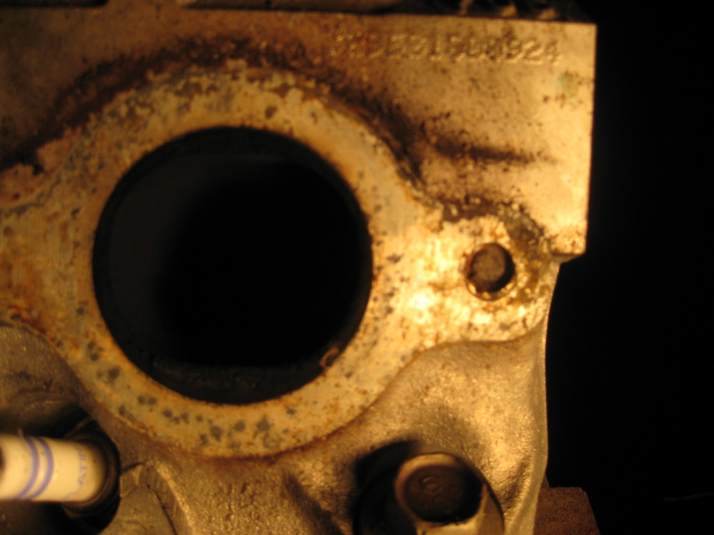
I got the new oil sump installed with the new, ridiculously expensive o-ring gasket, then this happened. This is the oil cooler block-off plate on the oil pan. I was using the torque wrench and tightened the bolts down evenly. The first bolt went on fine but the torque wrench didn't click on the second bolt. I started thinking something was wrong, so I tested the torque wrench on another bolt and it clicked fine. I went back and it did not click on the oil pan bolt. I went back and forth about three times until finally I determined something was wrong and I was turning way too hard for such a small bolt. Trusting the wrench more than myself, I decided to go just a little further to see if I could get the click, and that's when it snapped off. It was very late at night and this was the last bolt I had to finish the oil pan installation. It was disgusting.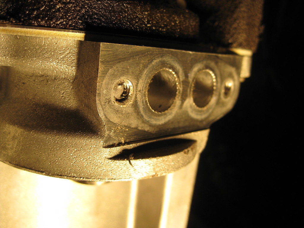
Because the bolt was not rusted and the head was broken off there was no tension on the threads. I was very fortunate that a chisel and hammer was able to get enough bite to slowly turn the broken off bolt until I had enough sticking out to get some pliers to get a grip and pulled it the rest of the way out.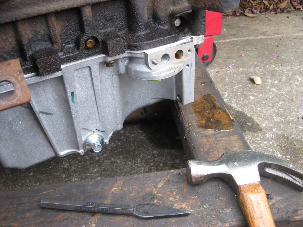
The exhaust manifold bolt was another story. I first applied a liberal amount of BP Blaster, heat and a hammer to try to break the rust bond loose. I attempted to build up weld on the end of the bolt (the heads are aluminum) so that I could then weld a nut on the end and turn it with a wrench. This effort was in vain and after a lot of time spent on this I moved on to drilling out the broken bolt. I purchased a heli-coil kit for the hole. A heli-coil is a series of threads which is screwed into an oversized, threaded hole after broken bolts or stripped threads are drilled out which allows the original bolt size to be reused.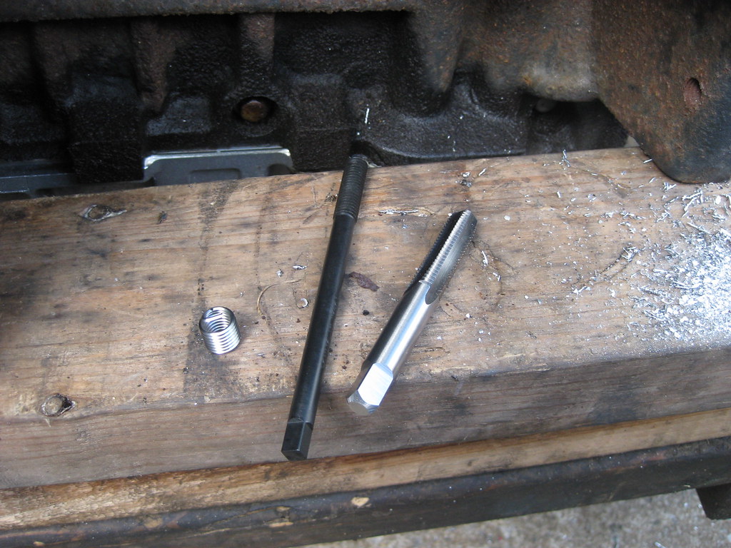
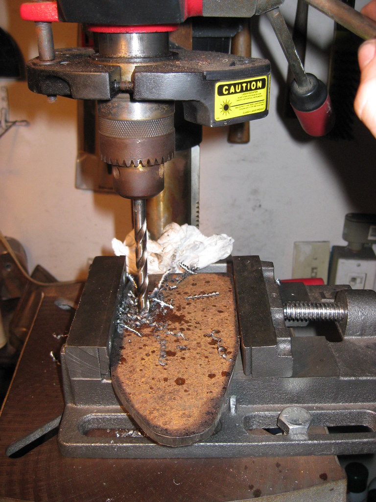
I drilled out the broken bolt, using tape on the bit to ensure I drilled to the right depth and a stud in the adjacent bolt hole to aid as a guide in drilling the new hole as straight as possible.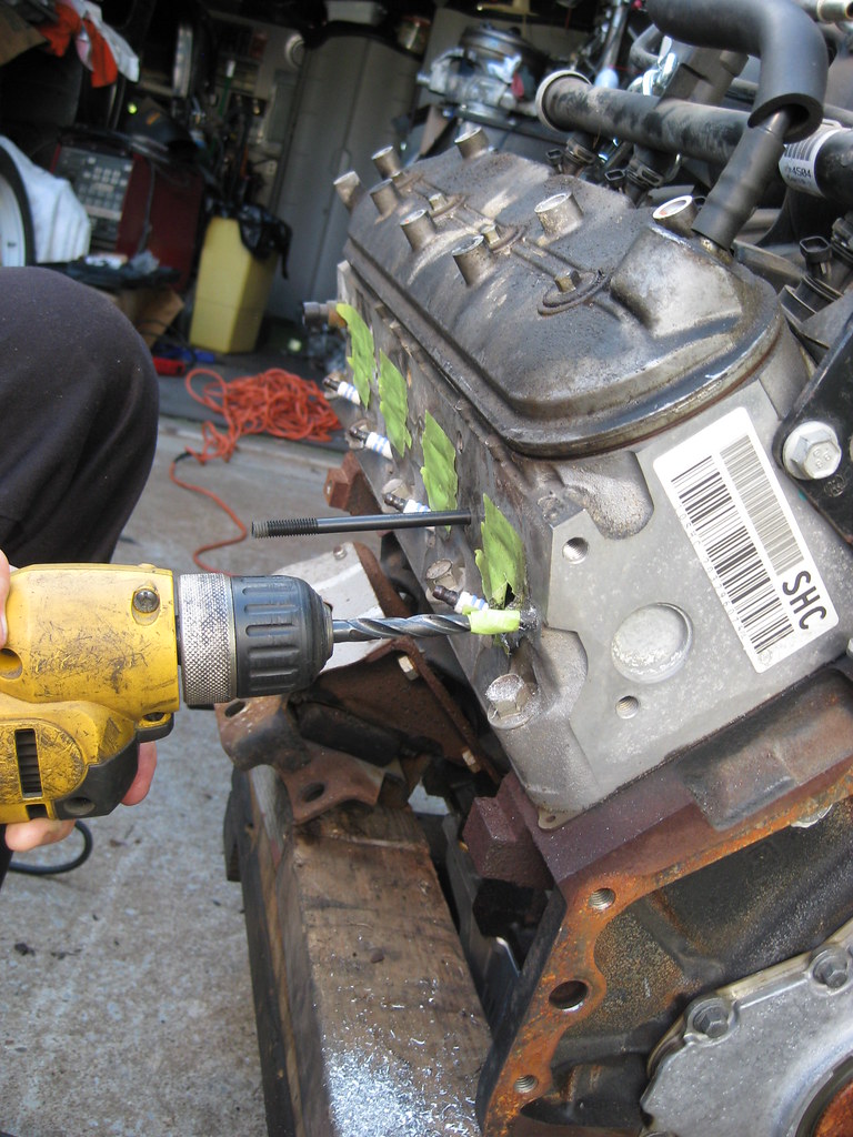
This is where the engine lived, placed by the tractor, protected by a tarp, until the new parts came in.
The BRP engine mounts did not fit as they were supposed to. I tried every combination of holes possible and there was nothing that would work. This picture shows how far off the bolt hole was.
I was able to indicate with a marker from the backside where to drill for the motor mount. I called the company and they instructed me to install the engine and get the fitment to determine which top hole I should drill out. For the amount of money this kit cost, this should absolutely not happen.
With off-set hole drilling like this, the drill press helps a lot.
However, the drill press still can quite finish the job because of the way the new hole was offset inside the old hole. I have to use a file to get the finishing touches.
After quite a bit of work, they fit.
I drained the torque converter from the new transmission in anticipation of the installation.
I ordered a new oil pan from a 1998-2002 GM F-body. This would be a V8 Camaro Z-28 or Pontiac Trans Am. I also ordered a new gasket. If I only knew then what I know now.
With the new oil pan in, I began removing some components off of the motor for installation.
The old oil pan from the 5.3 sits much lower than the F-Body pans. This causes the bottom of the pan to sit too far below the frame of the car, leaving it vulnerable to damage and thus catastrophic engine failure.
When I removed the exhaust manifolds I found that the rear driver side bolt was already broken off inside the block. That was unfortunate, but not entirely unexpected for an exhaust manifold bolt.
I got the new oil sump installed with the new, ridiculously expensive o-ring gasket, then this happened. This is the oil cooler block-off plate on the oil pan. I was using the torque wrench and tightened the bolts down evenly. The first bolt went on fine but the torque wrench didn't click on the second bolt. I started thinking something was wrong, so I tested the torque wrench on another bolt and it clicked fine. I went back and it did not click on the oil pan bolt. I went back and forth about three times until finally I determined something was wrong and I was turning way too hard for such a small bolt. Trusting the wrench more than myself, I decided to go just a little further to see if I could get the click, and that's when it snapped off. It was very late at night and this was the last bolt I had to finish the oil pan installation. It was disgusting.
Because the bolt was not rusted and the head was broken off there was no tension on the threads. I was very fortunate that a chisel and hammer was able to get enough bite to slowly turn the broken off bolt until I had enough sticking out to get some pliers to get a grip and pulled it the rest of the way out.
The exhaust manifold bolt was another story. I first applied a liberal amount of BP Blaster, heat and a hammer to try to break the rust bond loose. I attempted to build up weld on the end of the bolt (the heads are aluminum) so that I could then weld a nut on the end and turn it with a wrench. This effort was in vain and after a lot of time spent on this I moved on to drilling out the broken bolt. I purchased a heli-coil kit for the hole. A heli-coil is a series of threads which is screwed into an oversized, threaded hole after broken bolts or stripped threads are drilled out which allows the original bolt size to be reused.
I drilled out the broken bolt, using tape on the bit to ensure I drilled to the right depth and a stud in the adjacent bolt hole to aid as a guide in drilling the new hole as straight as possible.
07-04-2018, 04:17 PM
#27
After drilling the new hole, I used the supplied tap that comes with the kit. I then inserted the heli-coil into the oversized, newly tapped hole. I applied a very small amount of blue loctite. Some people say definitely apply loctite, some people say definitely do not. I chose to add a very small amount. Loctite helps hold threads so they do not back out once installed.
Drilling straight in the hole was very difficult because the bolt was broken off inside the hole and the end of the bolt was not a flat surface, which caused the drill bit to want to walk. I used a punch to help center the bit as much as possible, but it was not a perfect effort. Breaking the tang off of the back of the heli-coil finished the process. It's not particularly pretty, but it worked.
The mating surfaces of the engine block that bolt to the transmission and crank surfaces that bolt to the flywheel had surface rust that I wanted to clean away. I couldn't find my air grinder for the longest time until I remembered I had loaned it out and forgot to retrieve it. At this time I also noticed, unfortunately for the first time, that one of the transmission alignment dowels for the engine block was missing. I ended up having to drive to the nearest GM dealership and pay five dollars for a new one, which caused a delay in progress.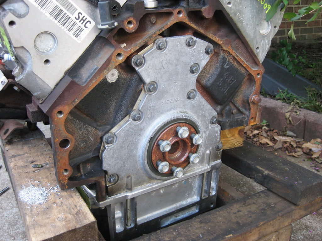
With the back of the block cleaned up and primered and the new dowel pin in place I got the transmission ready to be attached to the motor. After spending a while trying to determine the correct torque specs for all the different bolts I attached the flywheel, again using blue loctite. I noticed that the flywheel dowel was missing as well but a search on the internet revealed that many motors either didn't use a dowel originally or the dowel isn't necessary so I opted to leave it off. I filled the torque converter with new transmission fluid and installed it on the transmission. These converters must install with 3 successive clicks while spinning the converter. When the converter is approximately 1 1/8 inches behind the mounting pads of the bellhousing it is properly in place. Failure to locate the converter in this way will end up in broken parts and spent money.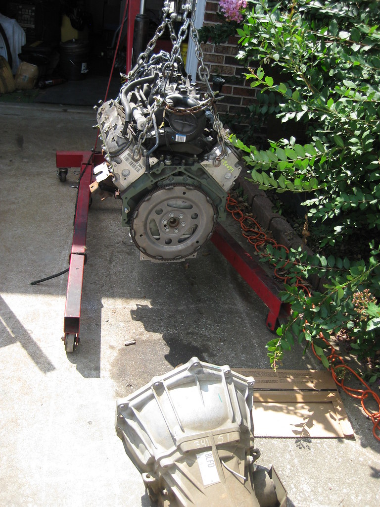
The mounting hardware for the bellhousing and the torque converter to flywheel bolts are special hardware. I ordered them online and awaited their arrival. I also spent a significant amount of time researching what anti-seize to use when putting aluminum against steel. I found there are as many opinions about this as there are people. Apparently the copper anti-seize I typically use is bad for applications in which aluminum will be against steel. I ended up using an Aluminum-based anti-seize for the dowel pins and blue loctite for the bellhousing and torque converter bolts. The torque converter bolts were difficult to access and required a universal joint and an extension in order to use the torque wrench. Because of my previous experience with the torque converter I was very afraid these bolts were going to snap. They seemed to be torquing down in a strange way. I successively tightened them down in very small increments, scared all along the way that they were going to snap off. The wrench had to be held in exactly the right position for it to click as it was supposed to.
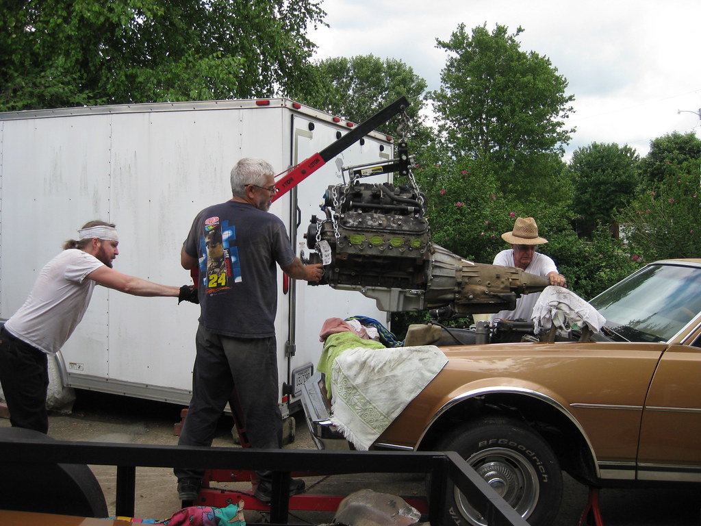
I first attempted to install the BRP transmission mounts but found their incomplete instructions to be prohibitive. I had previously had to use my wife's social media account to send them a message about further detail on installation. They did response, however the picture and explanation sent still wasn't completely sufficient to explain the installation. I later found that despite their claims that no drilling is necessary for this kit, one huge reason why I purchased this specific kit, drilling is in fact going to be necessary for not only the engine mounts, but also for new holes in the frame for a part of the transmission mount. I also ended up painting the parts black. Fortunately, dad stopped by and offered to help with the installation. I really didn't want to have to remove the intake manifold and worry about the problem of something going wrong with the re-installation. In order to get the block-leveler to fit with the intake on I had to hook chains to the chains on the leveler, which meant I had to go purchase new grade 8 bolts to fit it all together. We probably spent longer getting the hoist to lift the engine without damaging the intake than if we had just removed the intake. We would end up fighting this thing until 12:30 that night. The engine hoist was hitting the front bumper and wouldn't go back far enough to position the engine so it would go in the car. To make a very, very long story short we ended up using a series of jack and hoist positions and a lot of pushing and grunting and after several hours managed to shoehorn it in. To say things were tight would be an understatement.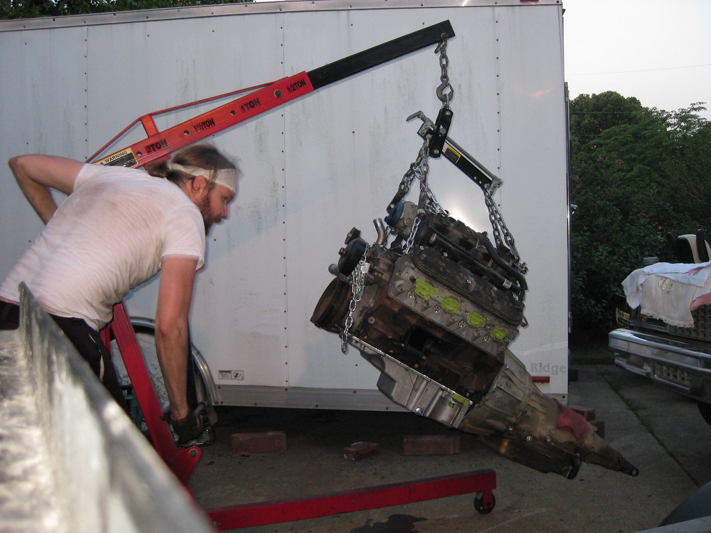
For a while, we had an audience.

After playing with the engine placement and transmission alignment with the hoist and jack for a very long time we finally relented that the engine, with the F-Body oil pan, will not fit. The sump area of the oil pan hit the crossmember, not allowing the engine to move far enough to the front of the car. The engine mounts will not line up with the holes in the frame. We did finally get one engine mount bolt in, but that was all. According to what I have read, this engine mount kit will allow me to keep all the original drive accessory components in their original locations, like the copressor and alternator. Because of this, new motor mounts were an option I wanted to reserve as a last resort.
The next day I was destroyed. Between this and other responsibilities and projects which had to be completed that day I ended up working outside in the heat between 18 and 19 hours that day and ended up getting overheated. The next day we examined the measurements in the daylight to try to determine a solution. I determined there were two other oil pans which may solve my problem. The issue is that they are a trade off of benefits. One has plenty of front oil sump clearance, but has limited clearance on top of the crossmemeber. The other has plenty of room over the crossmember but has less room on the front of the sump. After a lot of reading on the internet I decided to go with the Holley 302-3 oil pan. Before ordering this pan I contacted an acquaintance to see if he would be able to modify and weld the aluminum pan just in case I needed a bit more clearance. He said yes so I ordered the pan and am currently awaiting its arrival.
The one bolt that could.
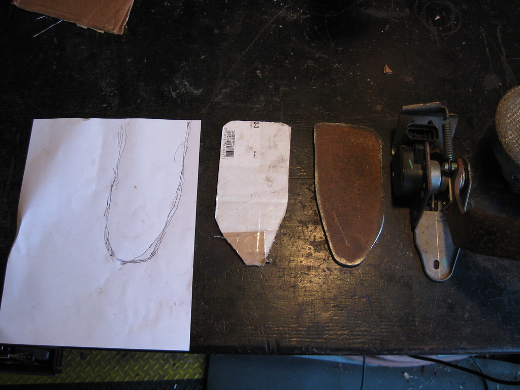
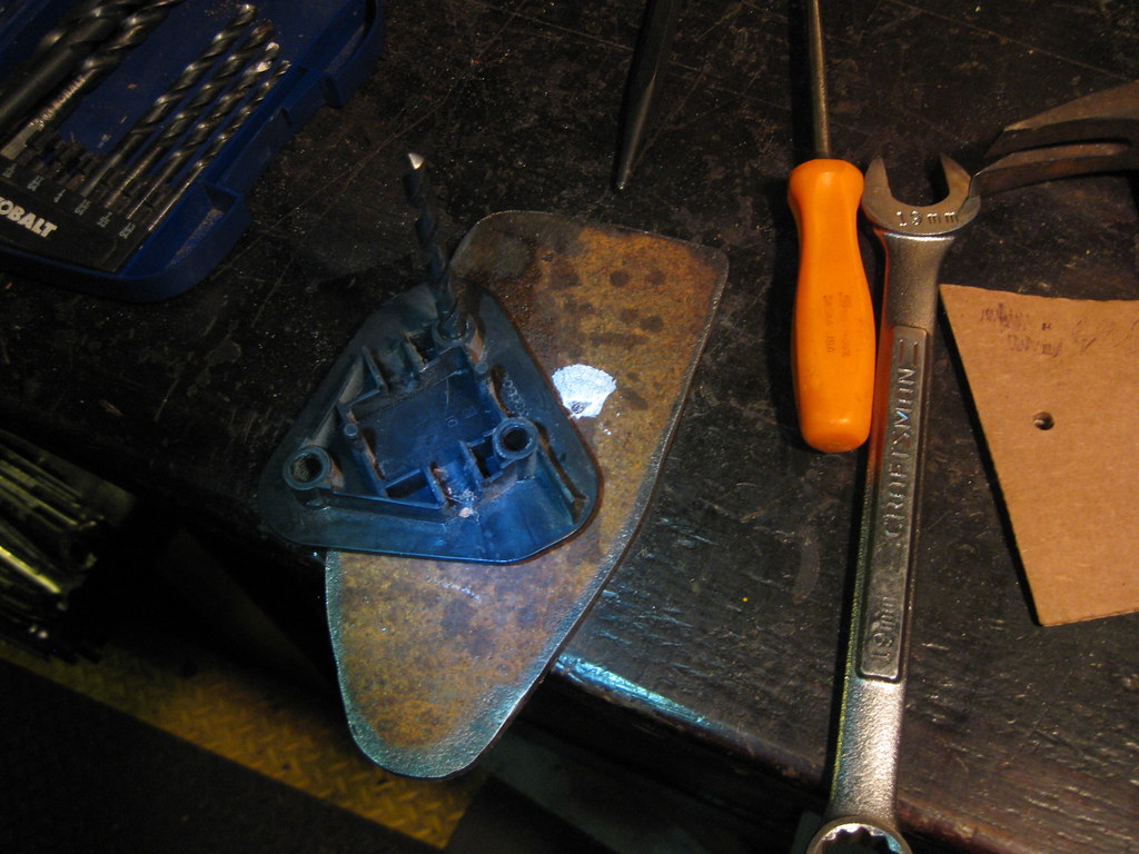
A project in the waits is modifying the electronic drive-by-wire (dbw) pedal. As you can see the original pedal (left) is oriented completely opposite of the new dbw pedal (right). I will have to cut and weld the new pedal arm to align it properly. This project will have to wait until I finish up the oil pan and install the new fuel pump/sending unit and accompanying lines and hardware.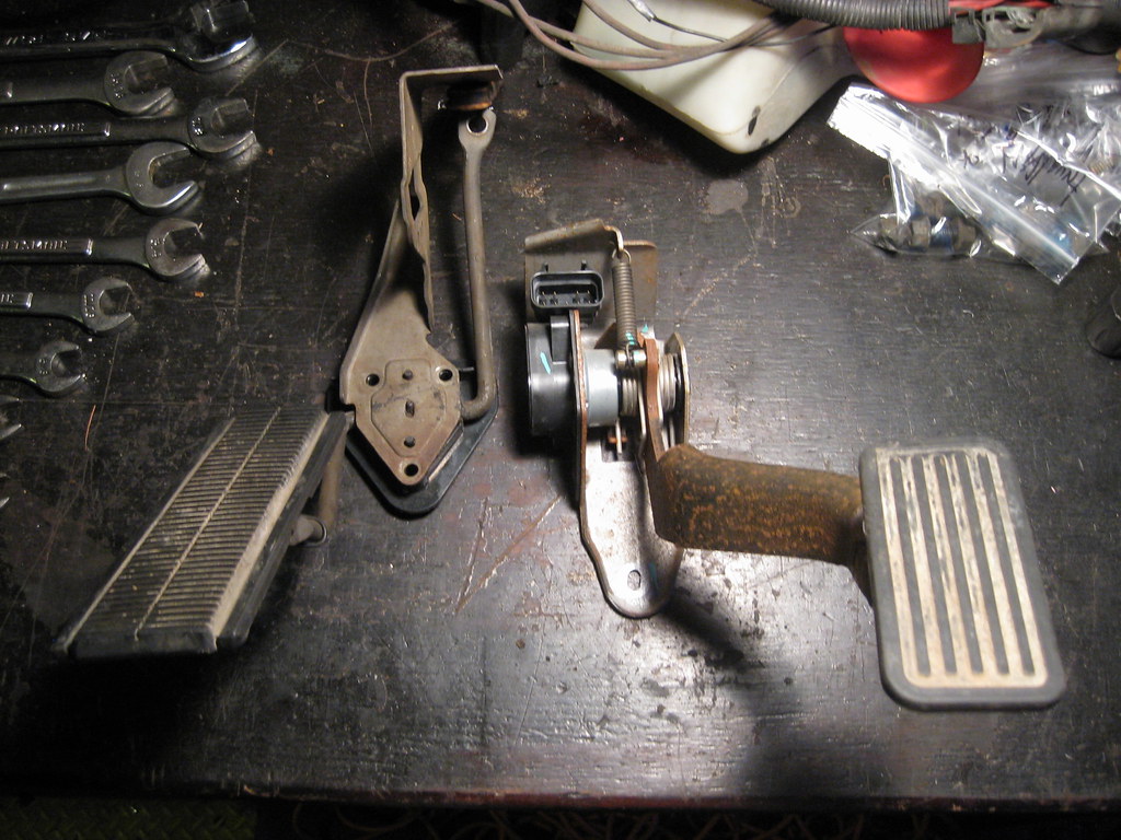
Drilling straight in the hole was very difficult because the bolt was broken off inside the hole and the end of the bolt was not a flat surface, which caused the drill bit to want to walk. I used a punch to help center the bit as much as possible, but it was not a perfect effort. Breaking the tang off of the back of the heli-coil finished the process. It's not particularly pretty, but it worked.
The mating surfaces of the engine block that bolt to the transmission and crank surfaces that bolt to the flywheel had surface rust that I wanted to clean away. I couldn't find my air grinder for the longest time until I remembered I had loaned it out and forgot to retrieve it. At this time I also noticed, unfortunately for the first time, that one of the transmission alignment dowels for the engine block was missing. I ended up having to drive to the nearest GM dealership and pay five dollars for a new one, which caused a delay in progress.
With the back of the block cleaned up and primered and the new dowel pin in place I got the transmission ready to be attached to the motor. After spending a while trying to determine the correct torque specs for all the different bolts I attached the flywheel, again using blue loctite. I noticed that the flywheel dowel was missing as well but a search on the internet revealed that many motors either didn't use a dowel originally or the dowel isn't necessary so I opted to leave it off. I filled the torque converter with new transmission fluid and installed it on the transmission. These converters must install with 3 successive clicks while spinning the converter. When the converter is approximately 1 1/8 inches behind the mounting pads of the bellhousing it is properly in place. Failure to locate the converter in this way will end up in broken parts and spent money.
The mounting hardware for the bellhousing and the torque converter to flywheel bolts are special hardware. I ordered them online and awaited their arrival. I also spent a significant amount of time researching what anti-seize to use when putting aluminum against steel. I found there are as many opinions about this as there are people. Apparently the copper anti-seize I typically use is bad for applications in which aluminum will be against steel. I ended up using an Aluminum-based anti-seize for the dowel pins and blue loctite for the bellhousing and torque converter bolts. The torque converter bolts were difficult to access and required a universal joint and an extension in order to use the torque wrench. Because of my previous experience with the torque converter I was very afraid these bolts were going to snap. They seemed to be torquing down in a strange way. I successively tightened them down in very small increments, scared all along the way that they were going to snap off. The wrench had to be held in exactly the right position for it to click as it was supposed to.
I first attempted to install the BRP transmission mounts but found their incomplete instructions to be prohibitive. I had previously had to use my wife's social media account to send them a message about further detail on installation. They did response, however the picture and explanation sent still wasn't completely sufficient to explain the installation. I later found that despite their claims that no drilling is necessary for this kit, one huge reason why I purchased this specific kit, drilling is in fact going to be necessary for not only the engine mounts, but also for new holes in the frame for a part of the transmission mount. I also ended up painting the parts black. Fortunately, dad stopped by and offered to help with the installation. I really didn't want to have to remove the intake manifold and worry about the problem of something going wrong with the re-installation. In order to get the block-leveler to fit with the intake on I had to hook chains to the chains on the leveler, which meant I had to go purchase new grade 8 bolts to fit it all together. We probably spent longer getting the hoist to lift the engine without damaging the intake than if we had just removed the intake. We would end up fighting this thing until 12:30 that night. The engine hoist was hitting the front bumper and wouldn't go back far enough to position the engine so it would go in the car. To make a very, very long story short we ended up using a series of jack and hoist positions and a lot of pushing and grunting and after several hours managed to shoehorn it in. To say things were tight would be an understatement.
For a while, we had an audience.
After playing with the engine placement and transmission alignment with the hoist and jack for a very long time we finally relented that the engine, with the F-Body oil pan, will not fit. The sump area of the oil pan hit the crossmember, not allowing the engine to move far enough to the front of the car. The engine mounts will not line up with the holes in the frame. We did finally get one engine mount bolt in, but that was all. According to what I have read, this engine mount kit will allow me to keep all the original drive accessory components in their original locations, like the copressor and alternator. Because of this, new motor mounts were an option I wanted to reserve as a last resort.
The next day I was destroyed. Between this and other responsibilities and projects which had to be completed that day I ended up working outside in the heat between 18 and 19 hours that day and ended up getting overheated. The next day we examined the measurements in the daylight to try to determine a solution. I determined there were two other oil pans which may solve my problem. The issue is that they are a trade off of benefits. One has plenty of front oil sump clearance, but has limited clearance on top of the crossmemeber. The other has plenty of room over the crossmember but has less room on the front of the sump. After a lot of reading on the internet I decided to go with the Holley 302-3 oil pan. Before ordering this pan I contacted an acquaintance to see if he would be able to modify and weld the aluminum pan just in case I needed a bit more clearance. He said yes so I ordered the pan and am currently awaiting its arrival.
The one bolt that could.
A project in the waits is modifying the electronic drive-by-wire (dbw) pedal. As you can see the original pedal (left) is oriented completely opposite of the new dbw pedal (right). I will have to cut and weld the new pedal arm to align it properly. This project will have to wait until I finish up the oil pan and install the new fuel pump/sending unit and accompanying lines and hardware.
07-04-2018, 07:32 PM
#28
TECH Senior Member
Just going on appearances here, but it looks like the new DBW pedal could screw to the firewall to the left of where the old one did, UNLESS it interferes with the brake pedal/linkage. Keep in mind, DBW gives you a lot of flexibility on pedal location. Screw it down, hook up the cable, and TADAAAH! The trick will be screwing it down so it feels right.
07-04-2018, 10:58 PM
#29
There are too many things in the way to move the pedal very far. Also, the original pedal screwed into two small round extrusions that stick out from the firewall which will make it difficult to remount in the area. I'll have to dig in later and see what I can come up with.
07-04-2018, 11:21 PM
#30
TECH Senior Member
Can you screw a plate or something to the extrusions like OEM pedal did, and attach the new pedal assy. to that? Obviously shooting in the dark here...
07-07-2018, 03:49 PM
#32

Originally Posted by
A project in the waits is modifying the electronic drive-by-wire (dbw) pedal. As you can see the original pedal (left) is oriented completely opposite of the new dbw pedal (right). I will have to cut and weld the new pedal arm to align it properly. This project will have to wait until I finish up the oil pan and install the new fuel pump/sending unit and accompanying lines and hardware.[url=https://c2.staticflickr.com/2/1734/42866342151_b60c8ca44c_b.jpg
A project in the waits is modifying the electronic drive-by-wire (dbw) pedal. As you can see the original pedal (left) is oriented completely opposite of the new dbw pedal (right). I will have to cut and weld the new pedal arm to align it properly. This project will have to wait until I finish up the oil pan and install the new fuel pump/sending unit and accompanying lines and hardware.[url=https://c2.staticflickr.com/2/1734/42866342151_b60c8ca44c_b.jpg
[/url]My Impala has an LS3 E-Rod set up, so my pedal is different. My 83 Coupe Deville, however has this pedal and connector. I found that this pedal was too big. Many people use the C-5 corvette pedal instead of the truck pedal. If I recall, you have to swap out the sensor from the truck to the vette pedal. Something to do with it pinned differently.
07-08-2018, 07:37 PM
#33
After much reading and consideration I decided to go with the Holley 302-3 oil pan. While I was awaiting for the new, new oil pan to arrive I pulled the sending unit out of the new (1994) Caprice gas tank.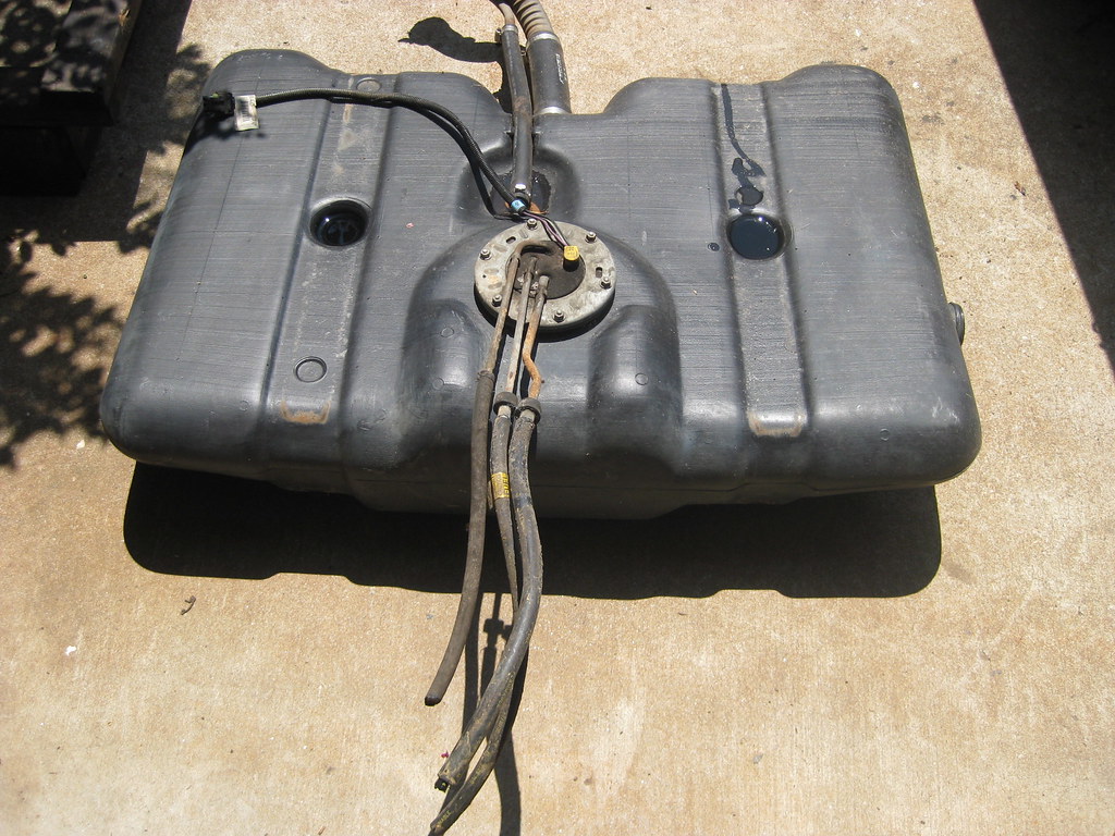
The picture below shows the reason this gas tank is used. The baffles shown hold the gasoline so when the fuel is low it does not slosh away from the pump. I cleaned away all of the debris.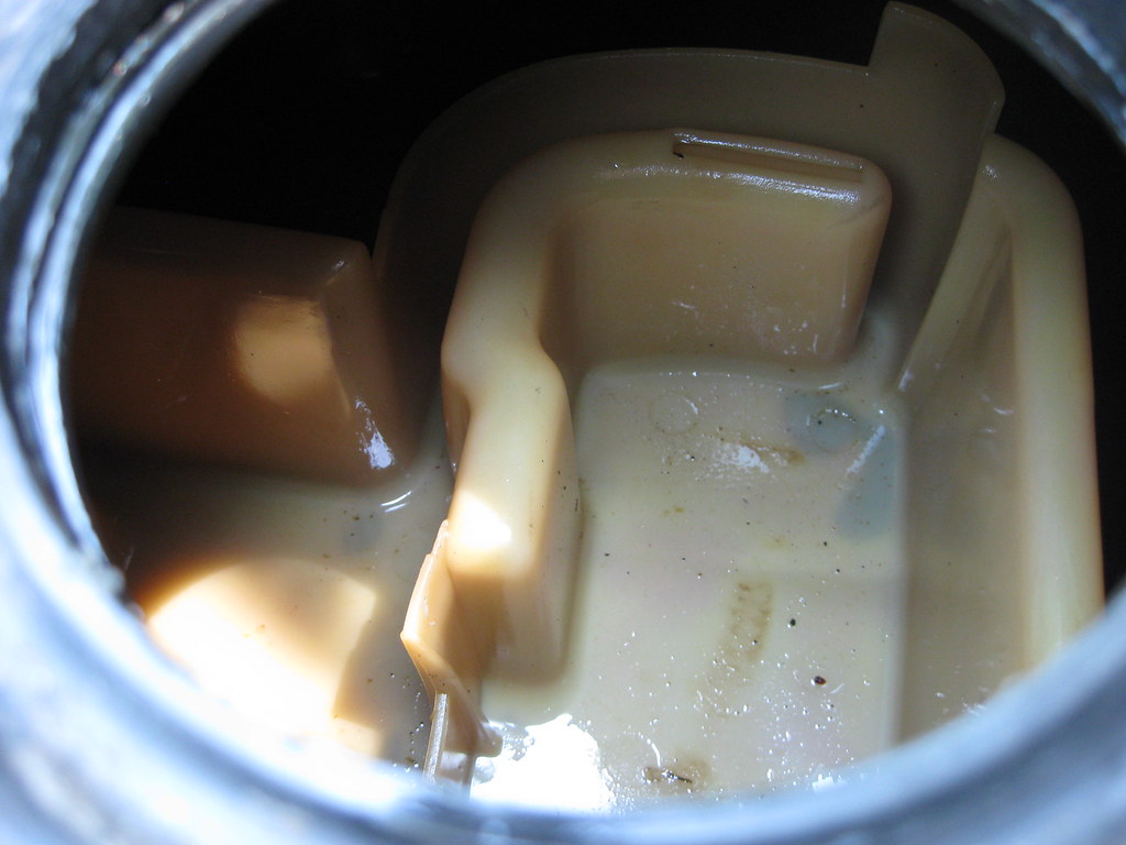
Then I tested the new Delphi sending unit assembly to make sure it was registering 0-90 ohms between empty and full.
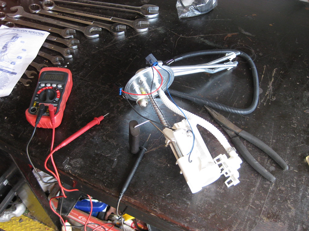
There were several differences between the original unit and the new unit. One was the way the wires hooked to the sender. Another was the addition of a blade connector hanging down from the lid of the sending unit assembly.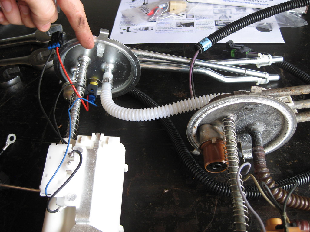
The wires on the new sending unit assembly were soldered and riveted to the sender. This mean you could not disconnect the wires and reconnect the wires from the new harness. Also, the manufacturer has changed their harness so the fittings and connectors are not the same as they used to be and past explanations on how to adapt this harness are no longer relevant. This company does not send instructions with their products. They require you to register for an internet forum which then must meet a moderators approval. As a result, I did not have access to the instructions the first day I tried to install these items. After receiving approval to the forum I found that the tech seemed unaware of the changes to the harness. I took the picture below and labeled all of the items with inquiries, however was still unable to get an answer to solve the problem. With help from a few other people online, I believe I have finally figured out how the new harness should be modified to fit on the sending unit assembly, but as of now I am not 100% sure.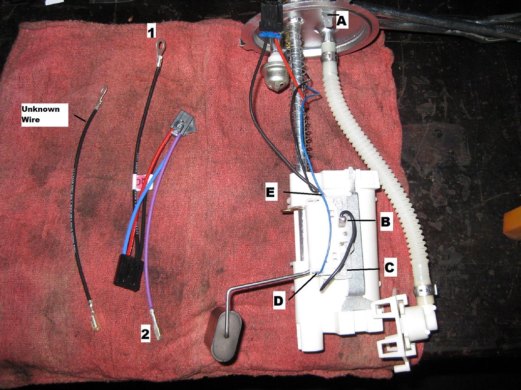
The new Holley oil pan arrived that week and on Saturday my Father-In-Law was in town and helped me pull the engine out once again.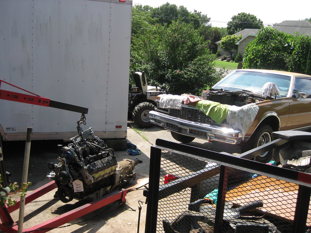
The Holley pan requires the use of an F-Body windage tray or a modified truck windage tray. Since I plan to use the F-Body oil pan that I'm now not going to be using on The Caprice for my '37 Chevrolet project and I won't have any future use for the old truck oil pan I decided to use the windage tray from the truck pan and modify it as described in the Holley's instructions. When I originally modified the pan below I cut it too long because I was using the portion of the directions which showed a close-up shot of the tray. I had to go back and recreate the cuts shown below at the next set of bolt holes on the tray.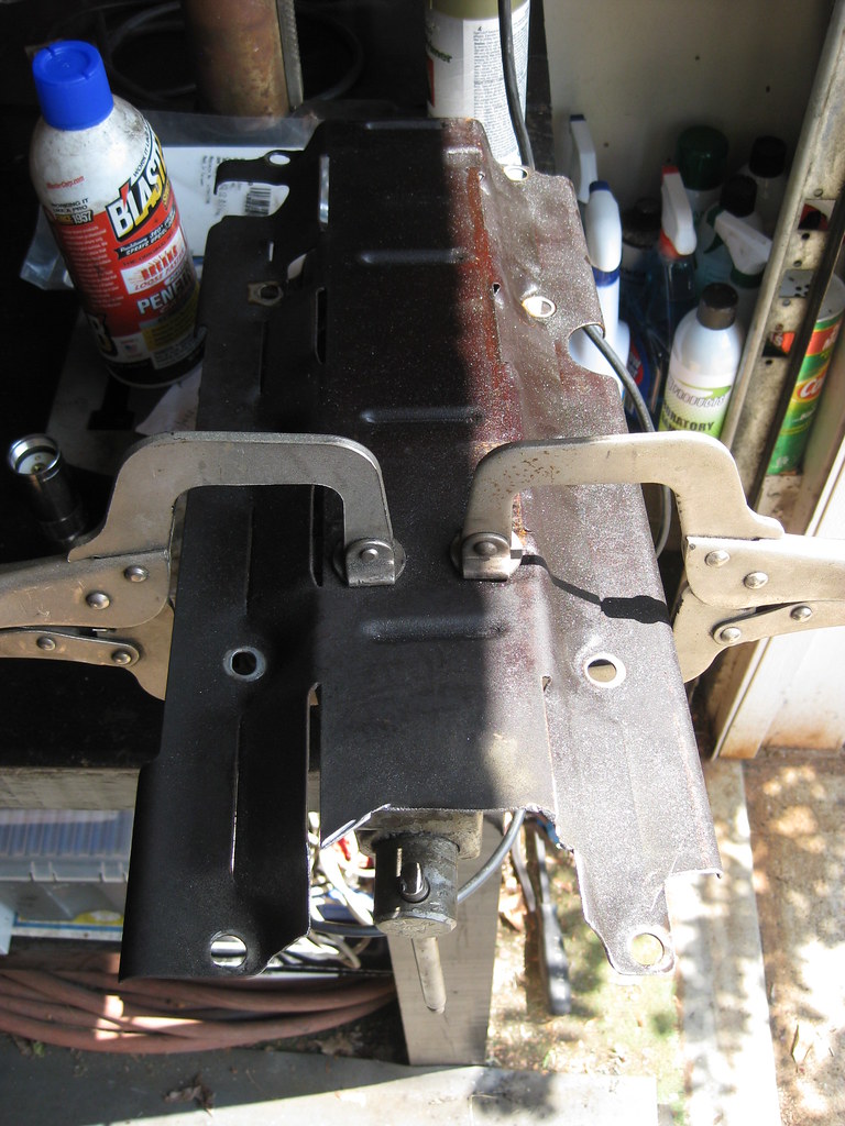
I had some business on Saturday and when I got back my Father-in-Law and Father had the F-Body oil pan removed.
We installed the modified windage tray, pickup tube and Holley oil pan and then installed the engine.
The new pan fit great! It has somewhere around 1 3/4" between the sump area on the pan and the crossmember. What a relief. Unfortunately, the compressor on the lower passenger side will not fit. This BRP kit has been an utter disappointment. First the frame mounts did not fit and required modification. Then the instructions were abysmally insufficient causing me to have to communicate with the company several times. I will say the company was good to respond to my communications. Then the transmission mount, which was not supposed to require any drilling, turns out to require some very difficult to locate holes to be drilled in the frame. Then the bolts for the transmission mount aren't long enough, or they sent too many shims, I'm not sure which yet. I have contacted the company again to try to find out. The engine was very difficult to align and took the three of us several hours to get bolted into place.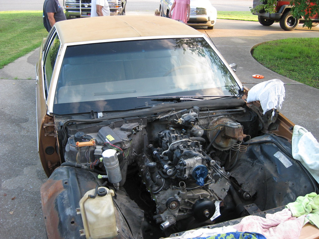
This is how much room I have between the firewall and the back of the engine. I know some guys like to push their engine back as far as possible, but I'm more concerned with having sufficient room to reach the back of the engine for maintenance.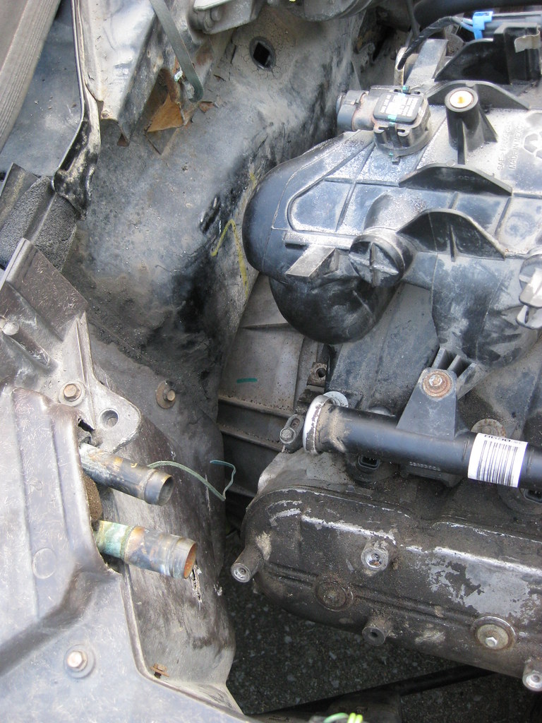
The photo below shows the compressor mount on the passenger side contacting the frame. The compressor obviously will not bolt in place and I am currently assessing my options on what to do about this situation. If I could move the entire engine forward 1 1/2" I believe the compressor would clear, but the oil pan would be very close. I test fit the new radiator to make sure I had enough room up front to play with. Other options involve cutting the frame to make room for the compressor or relocating the compressor. I believe the engine mount location will make notching the frame a non-option.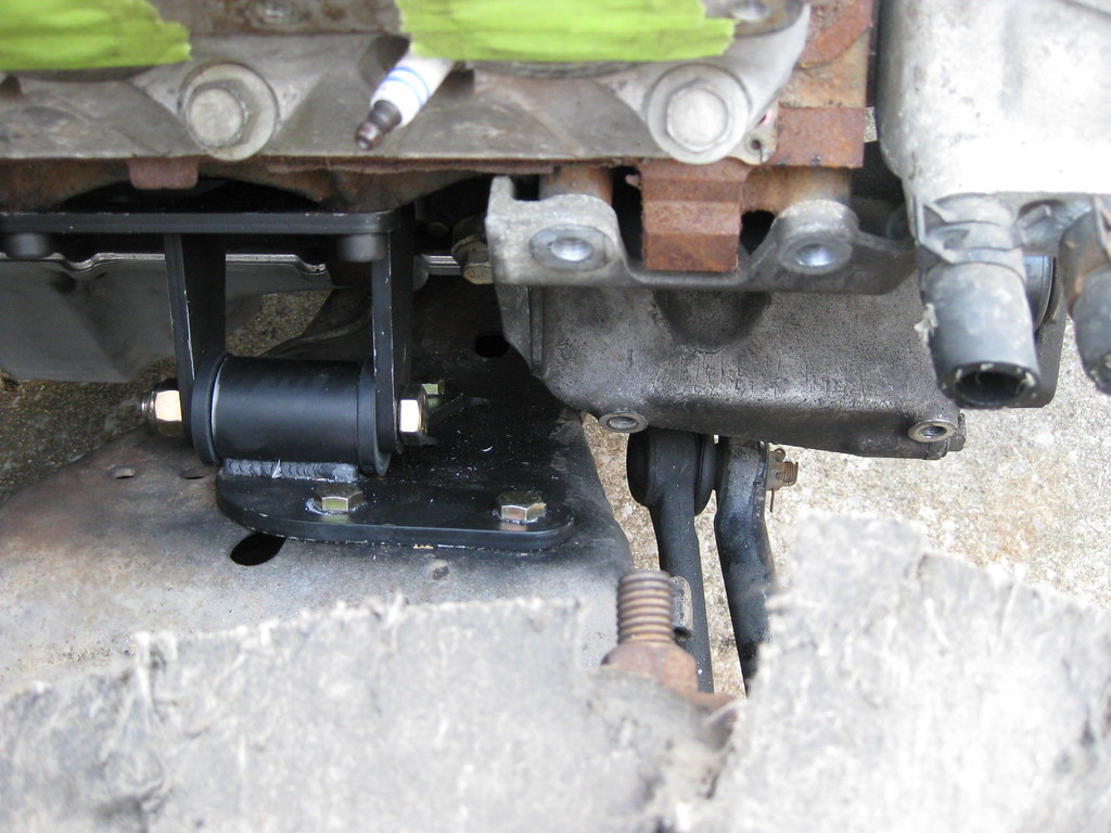
The picture below shows the reason this gas tank is used. The baffles shown hold the gasoline so when the fuel is low it does not slosh away from the pump. I cleaned away all of the debris.
Then I tested the new Delphi sending unit assembly to make sure it was registering 0-90 ohms between empty and full.
There were several differences between the original unit and the new unit. One was the way the wires hooked to the sender. Another was the addition of a blade connector hanging down from the lid of the sending unit assembly.
The wires on the new sending unit assembly were soldered and riveted to the sender. This mean you could not disconnect the wires and reconnect the wires from the new harness. Also, the manufacturer has changed their harness so the fittings and connectors are not the same as they used to be and past explanations on how to adapt this harness are no longer relevant. This company does not send instructions with their products. They require you to register for an internet forum which then must meet a moderators approval. As a result, I did not have access to the instructions the first day I tried to install these items. After receiving approval to the forum I found that the tech seemed unaware of the changes to the harness. I took the picture below and labeled all of the items with inquiries, however was still unable to get an answer to solve the problem. With help from a few other people online, I believe I have finally figured out how the new harness should be modified to fit on the sending unit assembly, but as of now I am not 100% sure.
The new Holley oil pan arrived that week and on Saturday my Father-In-Law was in town and helped me pull the engine out once again.
The Holley pan requires the use of an F-Body windage tray or a modified truck windage tray. Since I plan to use the F-Body oil pan that I'm now not going to be using on The Caprice for my '37 Chevrolet project and I won't have any future use for the old truck oil pan I decided to use the windage tray from the truck pan and modify it as described in the Holley's instructions. When I originally modified the pan below I cut it too long because I was using the portion of the directions which showed a close-up shot of the tray. I had to go back and recreate the cuts shown below at the next set of bolt holes on the tray.
I had some business on Saturday and when I got back my Father-in-Law and Father had the F-Body oil pan removed.
We installed the modified windage tray, pickup tube and Holley oil pan and then installed the engine.
The new pan fit great! It has somewhere around 1 3/4" between the sump area on the pan and the crossmember. What a relief. Unfortunately, the compressor on the lower passenger side will not fit. This BRP kit has been an utter disappointment. First the frame mounts did not fit and required modification. Then the instructions were abysmally insufficient causing me to have to communicate with the company several times. I will say the company was good to respond to my communications. Then the transmission mount, which was not supposed to require any drilling, turns out to require some very difficult to locate holes to be drilled in the frame. Then the bolts for the transmission mount aren't long enough, or they sent too many shims, I'm not sure which yet. I have contacted the company again to try to find out. The engine was very difficult to align and took the three of us several hours to get bolted into place.
This is how much room I have between the firewall and the back of the engine. I know some guys like to push their engine back as far as possible, but I'm more concerned with having sufficient room to reach the back of the engine for maintenance.
The photo below shows the compressor mount on the passenger side contacting the frame. The compressor obviously will not bolt in place and I am currently assessing my options on what to do about this situation. If I could move the entire engine forward 1 1/2" I believe the compressor would clear, but the oil pan would be very close. I test fit the new radiator to make sure I had enough room up front to play with. Other options involve cutting the frame to make room for the compressor or relocating the compressor. I believe the engine mount location will make notching the frame a non-option.
07-15-2018, 10:03 PM
#34
I have spent so much time researching my options for how to make a compressor fit on this car it's maddening. There are different types of compressors and different places to mount those compressors depending on what type they are. The best option would to be to get an entire accessory mounting kit to change all the accessories to better locations, but unfortunately those are very expensive and this project has already fast approached its budget. If I move the engine forward the power steering pump will hit the steering box. If I keep the compressor down low it will interfere with the crossmember. There isn't much room to cut and re-weld a relief in the crossmember because of the location of the engine mounts. The compressor is set back further than the rest of the accessories and runs on its own belt. There are kits to move it forward and have it run on the same belt as all of the other accessories, but even this will now allow it enough room to clear the crossmember. The company Sanden makes a mini-compressor that could possibly fit down low in the forward position, but it is my opinion that this will not give me the cooling capacity I would want for this car. Also, the location is so tight that I woudln't know for sure that it would fit until I ordered a kit and tried to install it. There are kits to move the compressor up, to the topside of the passenger side, and although this is an expensive option, and also creates a more cluttered engine compartment, after much consideration this is the route I chose to go with due to elimination of all other options. Unfortunately, no company that I have been able to find makes a kit to relocate the original compressor at all.
Holley offers two kits that mount a Sanden compressor up top. The kits include all the hardware, brackets, pulleys and idlers necessary for the installation. One kit includes a Sanden 508 compressor and the other kit includes the Sanden SD7 compressor. This is where the problem comes in. I ordered the Holley SD7 kit from an online company, Summit Racing. When it arrived, I found that they had included a SD7 mini-compressor. Sanden produced two compressors that I am interested in for my application, a 508 and a SD7. Within each kind, there are 3 types. The SD7 has two regular sized versions and also makes a SD7-B10, which is a mini-compressor which is physically smaller and has reduced cooling capacity. Some have indicated anecdotal evidence that this smaller compressor has adequate cooling capacity in automobiles comparable or even larger than mine, however after reading the statistics for the output of each model given by Sanden I have concluded that I do not want to go with a mini-compressor. To my knowledge, there is no notation on the website I ordered the kit from that indicates the SD7 would be a mini-compressor rather than a full size. To further complicate things, I looked up the specifications of the kit I ordered and the kit which comes with the Sanden 508, a full sized compressor, and found that both kits come with exactly the same part numbers for the brackets and pulleys, meaning the only difference in the kits is the compressor. I looked into the details for the part number of the bracket that comes in the kit and found that it fits both the Sanden SD7 and the 508. Since my kit came with a SD7-B10 (mini) and the same kit will fit a 508 (full size), it seems to reason that the same brackets would fit the SD7 full size models. Rather than return the entire kit, which is quite large, I called Holley, and waited on hold for a while, to see if they would exchange the compressor. They said I would have to call Summit, the company which I purchased the product through. I called Summit, and waited on hold for a while, and understandably they are not familiar with the intricacies of what is included in each Holley kit because Summit sells thousands of parts from many different vendors. I explained the situation and they ended up calling Holley tech support. At this point the Summit support tech is acting as proxy between Holley and I because the tech refused to talk to both of us on a conference call. Holley denied there was any difference in size between the SD7 and 508. I had the SD7 they sent me on the table next to a 508 and there was, no doubt, a difference. I explained this to the lady on the phone at Summit and she ended up calling Holley tech 3 times. Each time, I had to hold for a lengthy amount of time. Each time, they assured her there was no difference between a SD7 and a 508, and refused to acknowledge that a SD7 "mini" existed. The lady at Summit, who was very understanding and helpful, finally told me I would have to call Holley. I called Holley, again, and waited on hold for almost an hour. When I finally spoke with the tech, they again told me there was no difference in compressors. I explained that there was, that I was physically looking at both and also provided the measurements given on the Sanden website as well as a vintage air website which specifically gave the difference in measurements between the SD7-B10 (mini) and a 508. Finally, the tech agreed there was a difference between the SD7 and 508, but said that all SD7s are the same size. I explained that there are 3 types of SD7s (2 regular sized and one mini) and the one included in the kit was a mini, and that since my kit fits a 508 (regular size) or a SD7, I naturally concluded it must be a regular sized SD7 that the kit was supposed to include, because again the website did not distinguish. The tech then told me that they simply order an SD7 from Sanden and there is no distinguishing as to what size it is. The tech explained they did not distinguish in their description on the kit because they do not offer anything other than the mini, so it is not listed as a description. This is not my first experience with customer service and I realize that a person must maintain an impartial and non-confrontational attitude when dealing with this issues or the results will become less than favorable. This situation was very frustrating and Holley has an issue with a lack of understanding of the product which they are selling. Unfortunately, there was little to no interesting in resolving this issue. My next step will be to call Summit and ask for the SD7 mini to be swapped out for a 508. Fortunately I made sure to get the direct line to the Summit tech so that when I call back I don't have to re-explain all of this information to a new person. I preferred to have a SD7 full size, however I believe the 508 will be an adequate substitution. Had I known the kit I ordered came with a mini, or had it been in the description of the kit when I ordered it I could have avoided this very frustrating and time consuming situation entirely.
I was supposed to go down to a local exhaust shop on Saturday and borrow some F-body manifolds to make sure they will fit before I try to buy some, but unfortunately I was preoccupied listening to the on-hold music from Holley all morning until the exhaust shop closed, so I didn't make it. While I was on hold, I rewired the fuel pump, which is another frustrating experience with a after-market LS swap manufacturer. I would say dealing with vendors, their products and their instructions has, without a doubt, been the most frustrating and difficult part of this process so far.
The car goes back into the air. I hope to one day have a shop. I spend a lot of my limited time just getting the car and tools pulled out and put up each time I have a chance to work on the project.
The company I ordered the fuel pump from also makes a harness upgrade for the wiring harness that is in the fuel tank going from the pump to the bottom of the lid on the fuel sending unit assembly. The harness they make is not updated to work with the new-style fuel sending unit assemblies which are now made, but rather are made to fit the stock, original style fuel sending unit assemblies, which, to my knowledge, are no longer made and have been updated. This gas tank is from a 1994 Caprice and the in-tank harnesses were a known issue due to poor design, hence the need for an updated harness.
The company does not provide instructions and requires each buyer to join an online forum to get instructions. When I received approval to join this forum I found that the techs giving the advice did not realize that their harnesses no longer work. I found a different helpful individual on a website devoted to B-bodies that had figured out much of this problem and he helped me a lot, however the company's harness had also been re-designed since he had worked on the problem, however the redesign did not help the harness fit with the new sending units. After several attempts at answers from the company's forum tech, which proved to be insufficient or outright wrong, I realized I would be better off to figure this out myself with the help of the individual from the B-Body forum. Here is part of what I did. I won't know if this solution works until I try to start the car.
I had to remove the sender from the sending unit assembly. On the newer style units, the wires to the sender are riveted or soldered.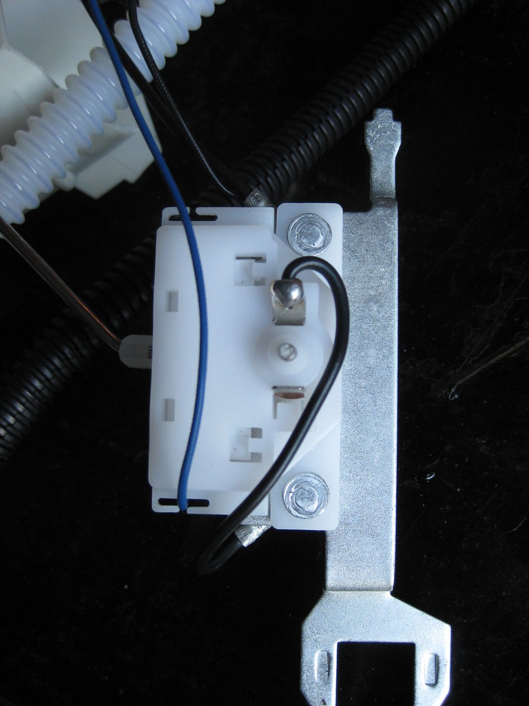
07-15-2018, 10:04 PM
#35
I had to drill out the top rivet and replace it with a screw and jam-nut to hold some of the new wires I would be adding. The wire for the sender provided by the company's kit was not long enough to reach the soldered location on the sender so I had to remove the connector from the original sending unit wire (blue wire) and replace the new harness' wire with the original one.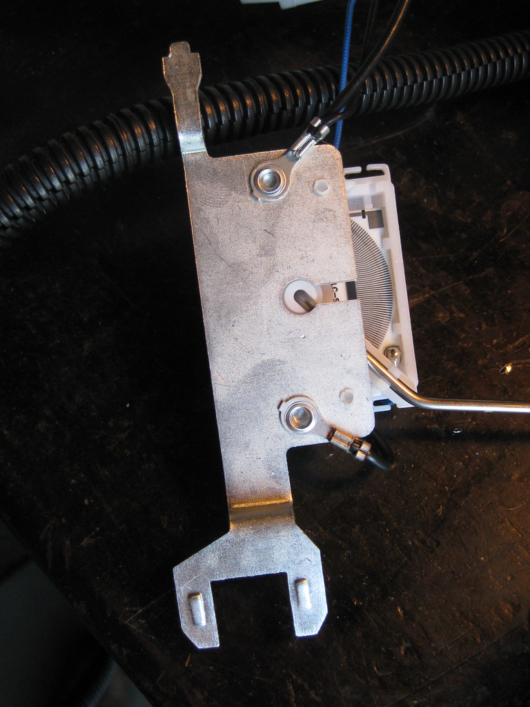
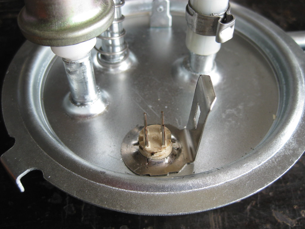
Part of the kit includes removing this connector and clamp from the sending unit assembly lid. I found removing this part to be fairly difficult.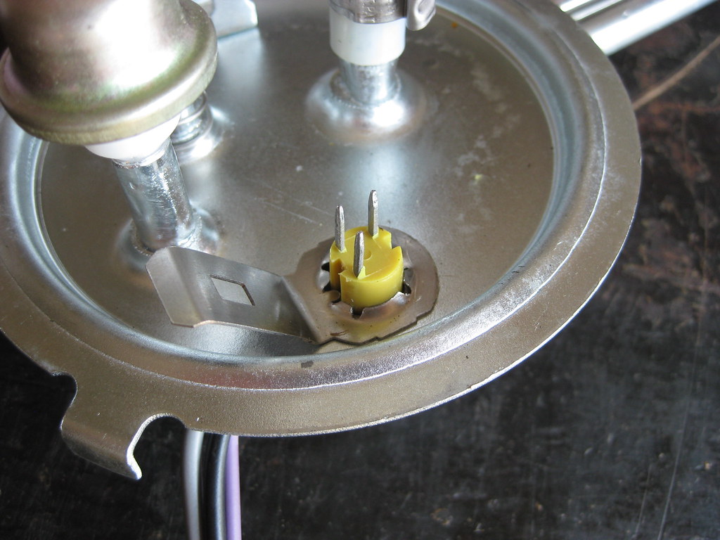
The new piece has 4 pins instead of 3.
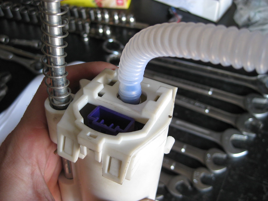
The fuel pump (purple) sits inside a case. I had to use a file to open up the hole so the new plastic hose could fit through.
I had to use these clamps to secure the plastic hose. I did not have experience with these clamps and it took a little while to figure out exactly how I was supposed to utilize them properly. Again, proper instructions would have been very helpful.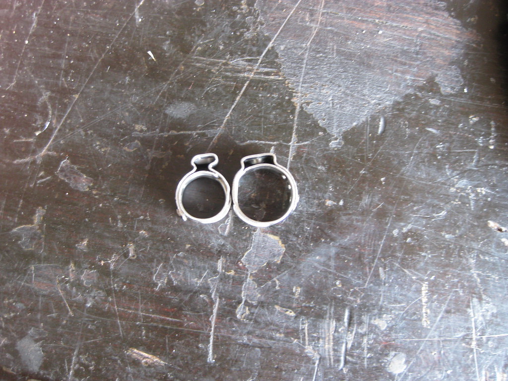
This is how I ended up wiring the final product. A 1/4 hole must be drilled in the lid so a brass stud can be installed which acts as an extra ground.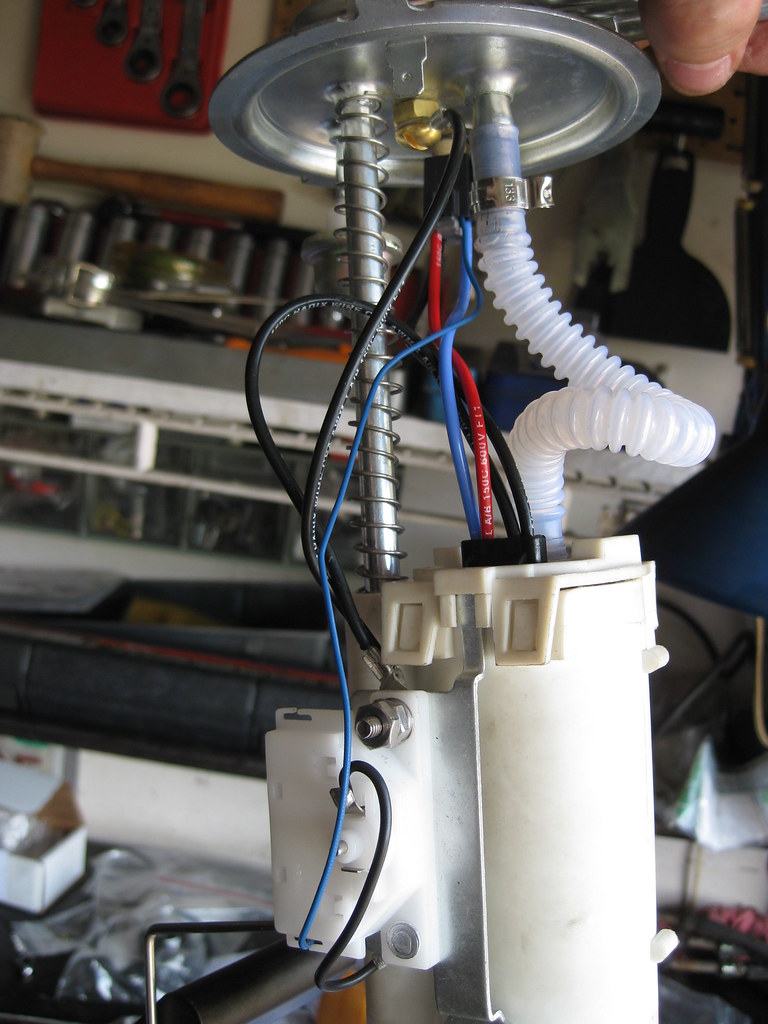
I then installed the assembly in the '94 Caprice gas tank. Fortunately, Dad happened to stop by and was there when I installed the unit and noticed I had installed it backwards in the tank. You would think I would have noticed when all the metal lines were pointed the wrong direction.
One thing that takes so long with projects like this is learning simple things you just didn't know and have no experience with. At first I was unable to get the AN fittings to clamp and secure the -6 fuel lines properly. After a lot of trial and more and more error I found out that these are not the same type of AN fittings as I have used in the past. These fittings are called PTFE fittings, which means they have the brass ferrule, or "olive" as they are referred to, in the picture below.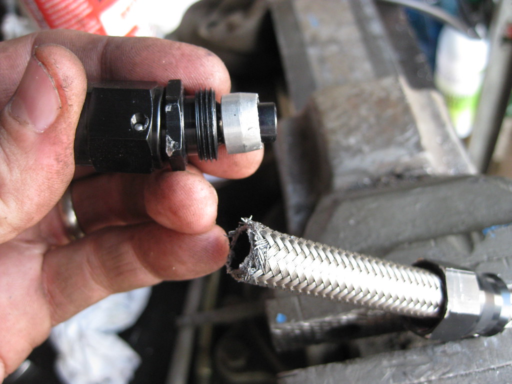
I was simply installing the fittings as shown below. This is incorrect. The proper way to use these fittings is to slide the fitting on the very right of this picture on first, then use a small screwdriver to peel the steel braids back away from the hose inside. The ferrule then slides over the hose but under the steel braid. When the fitting on the right in the picture below is then slid forward and screwed onto the threads it creates a sandwich of the tube from the fitting on the left going into the hose, then the hose, then the ferrule over the hose, then the steel braids over the ferrule and the fitting on the right on top. After I learned this, getting the fittings on the lines was not much trouble at all. Also, the threads of the fitting need to be lubricated. I used air tool lubricant. This step is on all the instructions I saw for these fittings. I forgot to use lubrication on one of the threads and when I got the fitting screwed together I could feel the heat from the friction.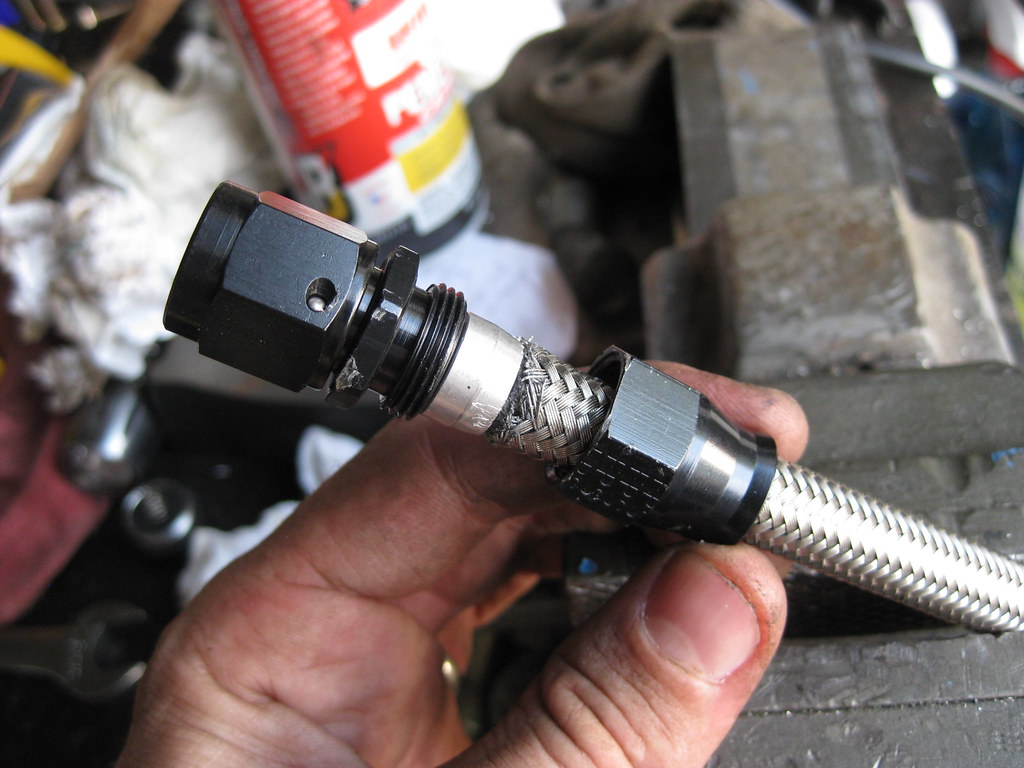
The adel clamps I ordered to secure the fuel lines would not fit with the original bolts that held the old fuel line clamps. I had to drill out the holes in each clamp and also trim down part of the flanges on each one of them.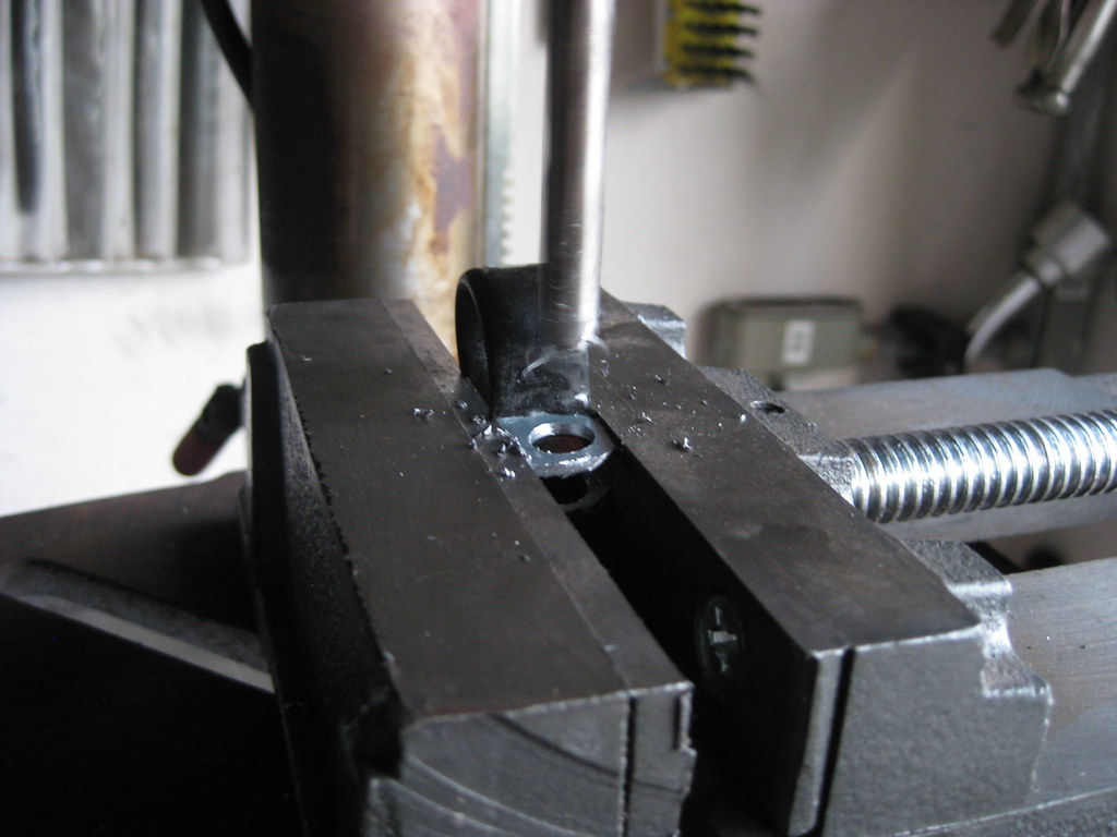
Part of the kit includes removing this connector and clamp from the sending unit assembly lid. I found removing this part to be fairly difficult.
The new piece has 4 pins instead of 3.
The fuel pump (purple) sits inside a case. I had to use a file to open up the hole so the new plastic hose could fit through.
I had to use these clamps to secure the plastic hose. I did not have experience with these clamps and it took a little while to figure out exactly how I was supposed to utilize them properly. Again, proper instructions would have been very helpful.
This is how I ended up wiring the final product. A 1/4 hole must be drilled in the lid so a brass stud can be installed which acts as an extra ground.
I then installed the assembly in the '94 Caprice gas tank. Fortunately, Dad happened to stop by and was there when I installed the unit and noticed I had installed it backwards in the tank. You would think I would have noticed when all the metal lines were pointed the wrong direction.
One thing that takes so long with projects like this is learning simple things you just didn't know and have no experience with. At first I was unable to get the AN fittings to clamp and secure the -6 fuel lines properly. After a lot of trial and more and more error I found out that these are not the same type of AN fittings as I have used in the past. These fittings are called PTFE fittings, which means they have the brass ferrule, or "olive" as they are referred to, in the picture below.
I was simply installing the fittings as shown below. This is incorrect. The proper way to use these fittings is to slide the fitting on the very right of this picture on first, then use a small screwdriver to peel the steel braids back away from the hose inside. The ferrule then slides over the hose but under the steel braid. When the fitting on the right in the picture below is then slid forward and screwed onto the threads it creates a sandwich of the tube from the fitting on the left going into the hose, then the hose, then the ferrule over the hose, then the steel braids over the ferrule and the fitting on the right on top. After I learned this, getting the fittings on the lines was not much trouble at all. Also, the threads of the fitting need to be lubricated. I used air tool lubricant. This step is on all the instructions I saw for these fittings. I forgot to use lubrication on one of the threads and when I got the fitting screwed together I could feel the heat from the friction.
The adel clamps I ordered to secure the fuel lines would not fit with the original bolts that held the old fuel line clamps. I had to drill out the holes in each clamp and also trim down part of the flanges on each one of them.
07-15-2018, 10:04 PM
#36
The fuel rail only has one line because this 2004 5.3 LY7 is a returnless style fuel rail.
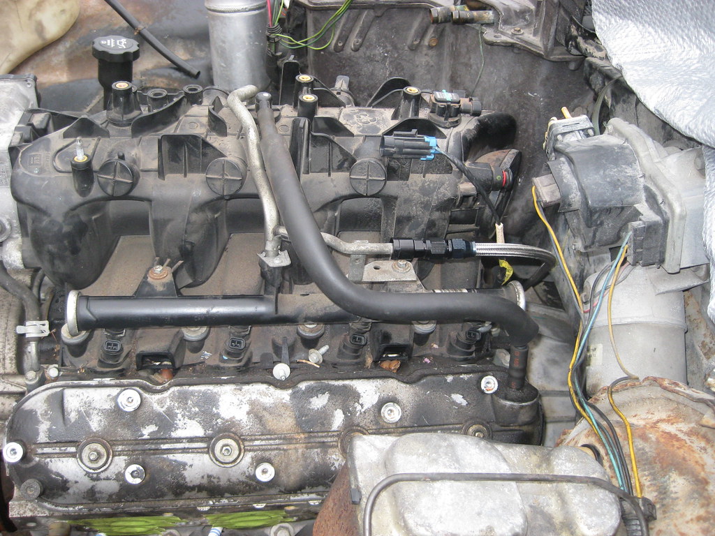
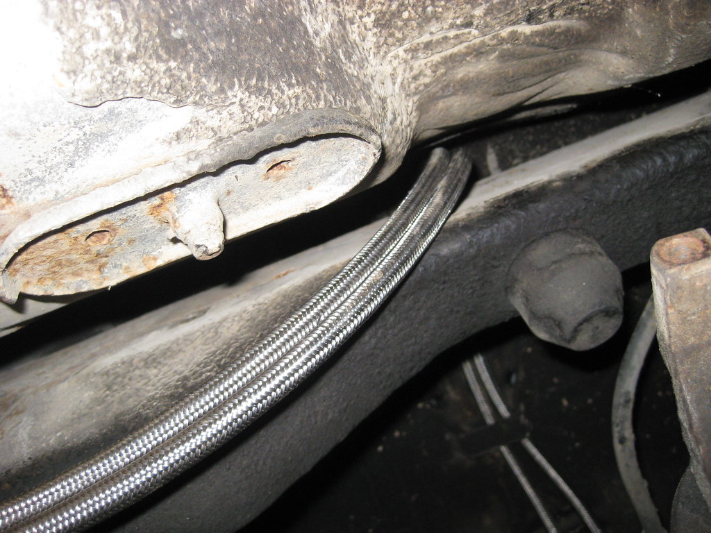
The line runs down the passenger side and over the frame rail to the filter/regulator, which I mounted mid-way on top of the framerail. I have not yet installed all of the clamps to secure the fuel line. I almost mounted the regulator in the very back of the car over the axle, and I saw where many people have done this, but I decided to move it forward, mid-way on the car. I don't have any evidence to support this but I feel as though this would give the regulator an easier time of managing the PSI in the shorter line running to the fuel rail than if I had mounted the regulator in the back of the car. The stock locations for these regulators seem to be about mid-way on the car as well, but this could also be a space requirement more than a design choice. Also, the pump I purchased was for an LT1 and is slightly under the 58 psi of what a LS motor requires. I have heard that others have used this setup with no problem, but I suspect that relieving any extra load on the regulator would be helpful.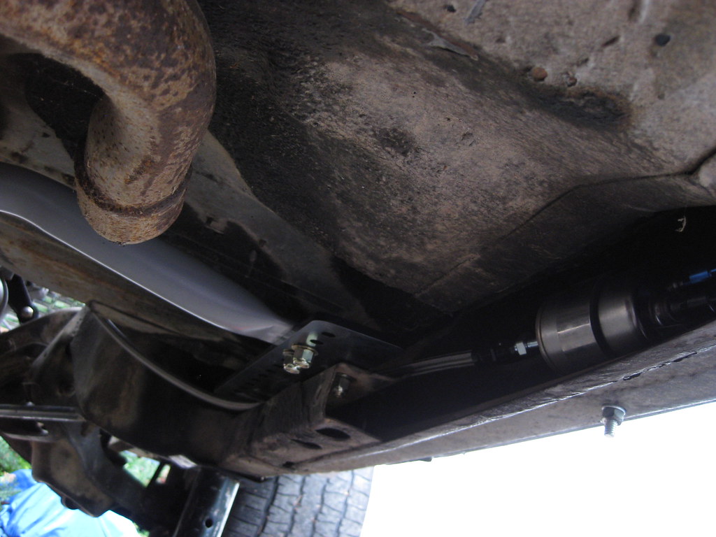
The line continues down the frame rail, using a stock location from the old fuel line for the new adel clamps.
Another reused stock clamp location using new adel clamps. These clamps seem to be a bit oversized for the -6 lines and I may end up replacing them with clamps that will hold the lines a bit tighter.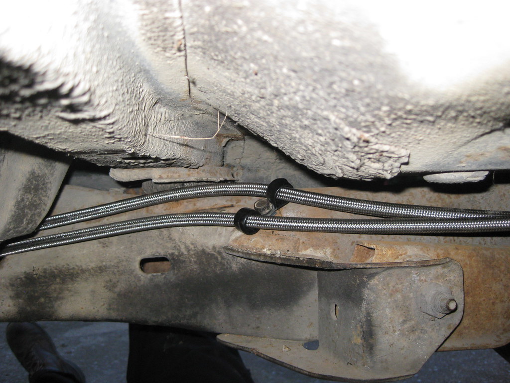
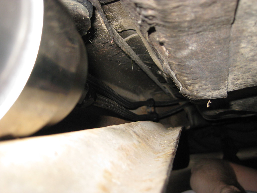
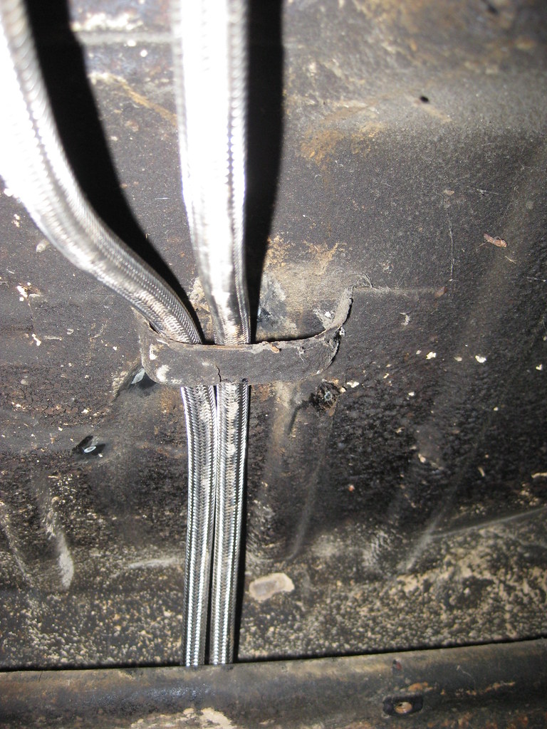
The line continues over the frame in the rear, which is over the top of the rear axle. I will add more clamps soon.
After going over the axle the lines go through the original fuel hose bracket.
They finally terminate at the tank. I have not yet installed the fuel tank vent tube.
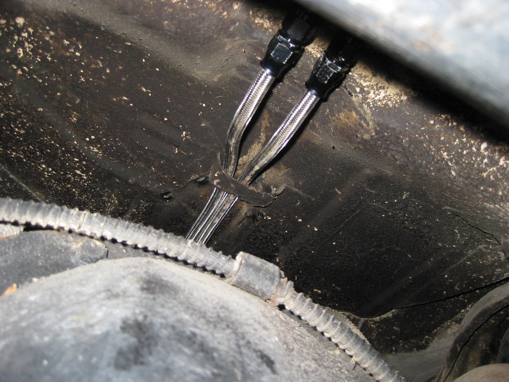
If you look right above the lines here you'll see the old exhaust hanger mount. I no longer use this mount because of the dual exhaust. I've removed this mount and I am going to weld a mounting tab to the bottom to provide a mounting location for two more adel clamps.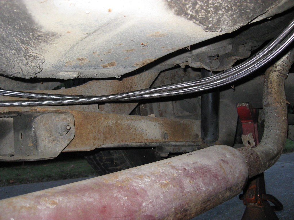
The line runs down the passenger side and over the frame rail to the filter/regulator, which I mounted mid-way on top of the framerail. I have not yet installed all of the clamps to secure the fuel line. I almost mounted the regulator in the very back of the car over the axle, and I saw where many people have done this, but I decided to move it forward, mid-way on the car. I don't have any evidence to support this but I feel as though this would give the regulator an easier time of managing the PSI in the shorter line running to the fuel rail than if I had mounted the regulator in the back of the car. The stock locations for these regulators seem to be about mid-way on the car as well, but this could also be a space requirement more than a design choice. Also, the pump I purchased was for an LT1 and is slightly under the 58 psi of what a LS motor requires. I have heard that others have used this setup with no problem, but I suspect that relieving any extra load on the regulator would be helpful.
The line continues down the frame rail, using a stock location from the old fuel line for the new adel clamps.
Another reused stock clamp location using new adel clamps. These clamps seem to be a bit oversized for the -6 lines and I may end up replacing them with clamps that will hold the lines a bit tighter.
The line continues over the frame in the rear, which is over the top of the rear axle. I will add more clamps soon.
After going over the axle the lines go through the original fuel hose bracket.
They finally terminate at the tank. I have not yet installed the fuel tank vent tube.
If you look right above the lines here you'll see the old exhaust hanger mount. I no longer use this mount because of the dual exhaust. I've removed this mount and I am going to weld a mounting tab to the bottom to provide a mounting location for two more adel clamps.
07-22-2018, 04:52 PM
#37
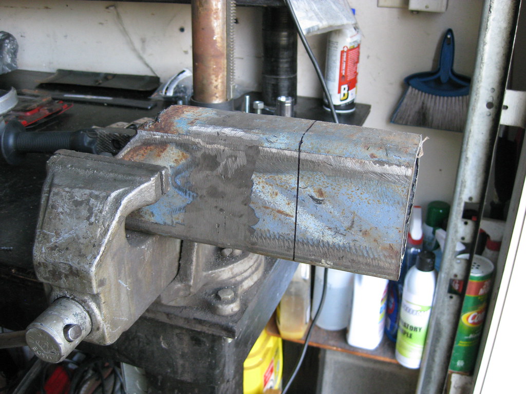
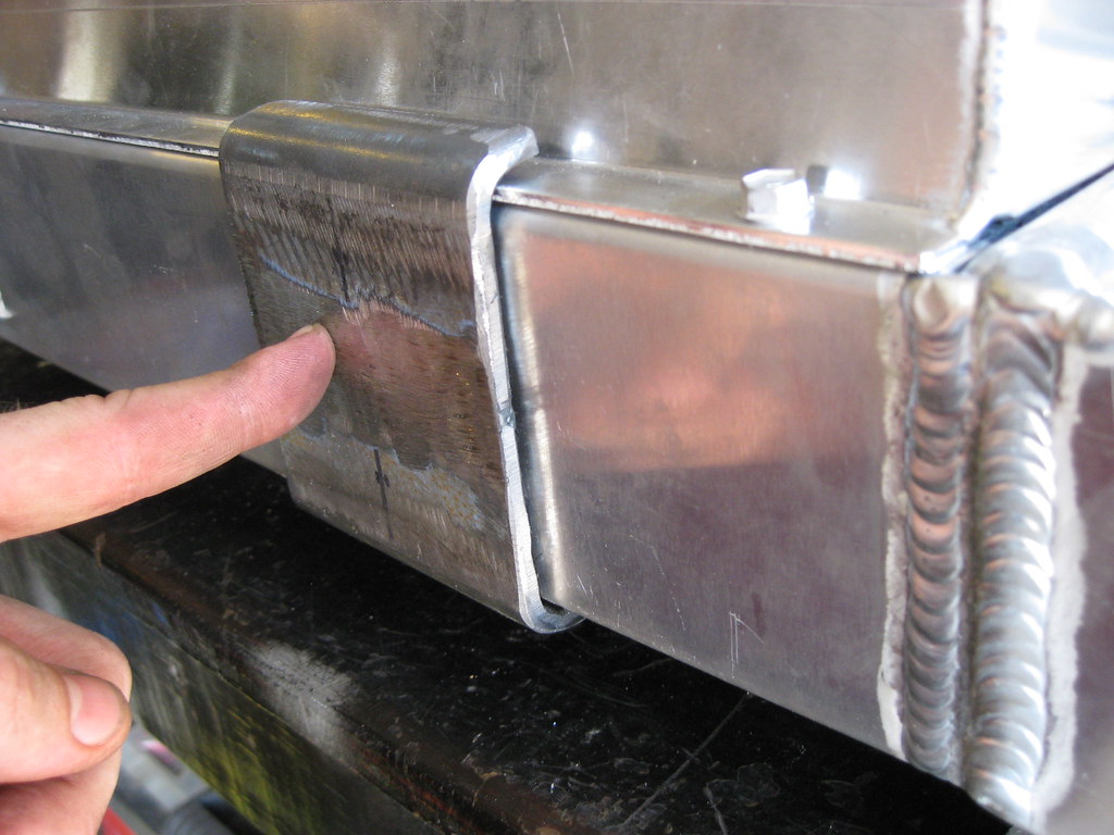
A friend that owns a muffler shop said he had some LS exhaust manifolds behind his shop if I wanted to search through all the scraps to see if there was anything that would fit. I was searching for F-body manifolds as the truck manifolds won't work but unfortunately couldln't come up with any. I spent a long time digging through all the pieces and pulled out two different types of manifolds. I brought them back home and neither of them would fit so I took them back and started back in on making some brackets. I had forgotten how long metal fabrication can take. I was again surprised at how few pictures can sum up hours of work. The below pictures took several days, including one full Saturday.
I removed the old exhaust hanger so that I could add a mounting bracket for the fuel lines.
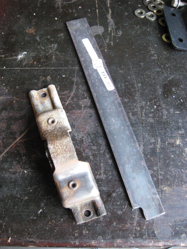 After after a lot of grinding dust, it looked like this. I will paint this and all of the other parts at one time when I have them finished.
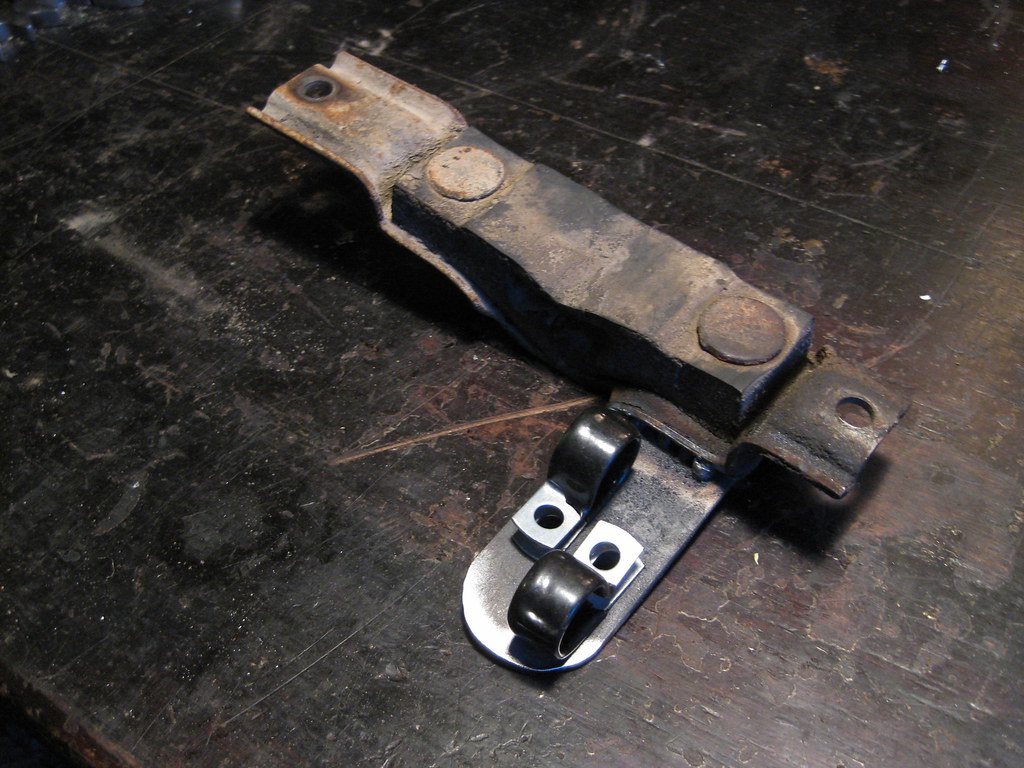
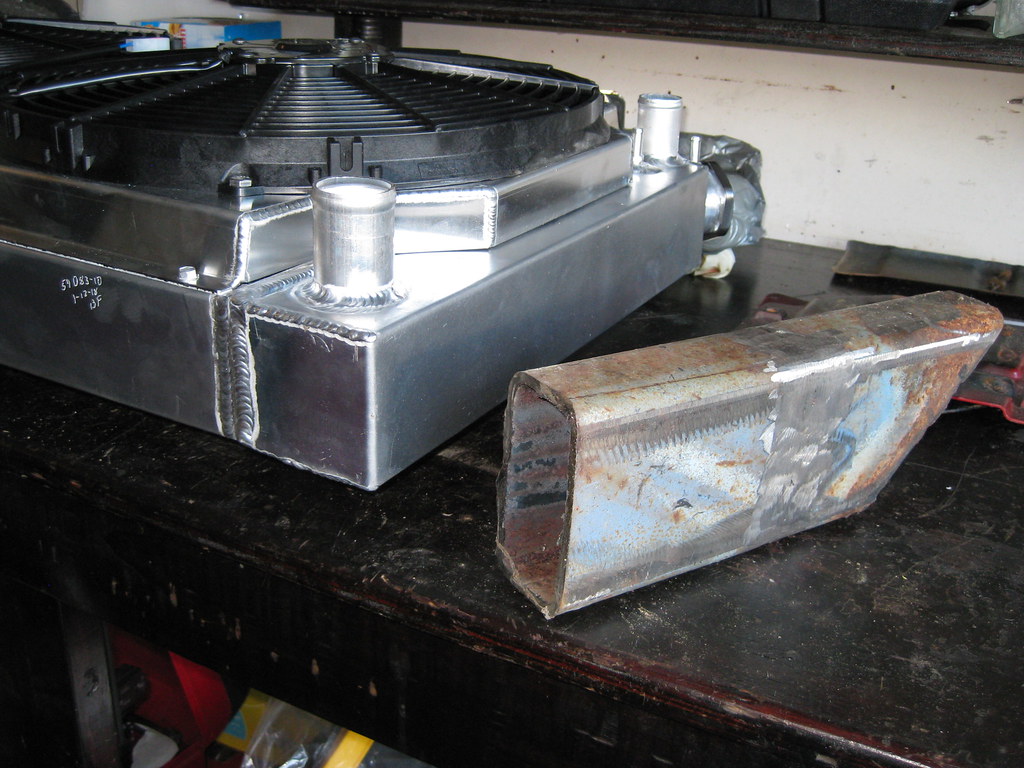
It was time to make the mounting brackets for the radiator. This part was particularly difficult for me to wrap my head around. There seem to be as many ways to mount a radiator as there are people, however I wanted to do it correctly. I tend to believe that if the frame flexes under torsion then hard-mounting the radiator would put undue stress on the aluminum welds of the piece. I wanted to dampen the radiator with rubber mounts as the automobile manufacturers do.
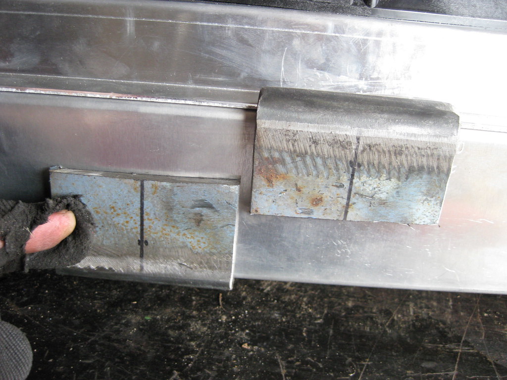
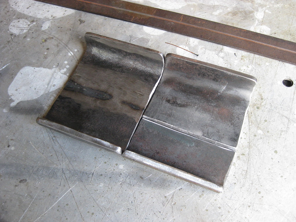
I scrounged through my scrap metal pile and found this piece. This was the very first piece of scrap metal I got at the scrapyard when I first got my welder to use for practice. I had probably cut this thing in half and put it back together 3 or 4 times, as well as laid a lot of beads on top of it. It was pretty close to the right shape and size to make bottom radiator supports.
I made some measurements and started burning through some grinding wheels.
I had a lot of grinding to do to smooth out all of the old practice beads I had put down.
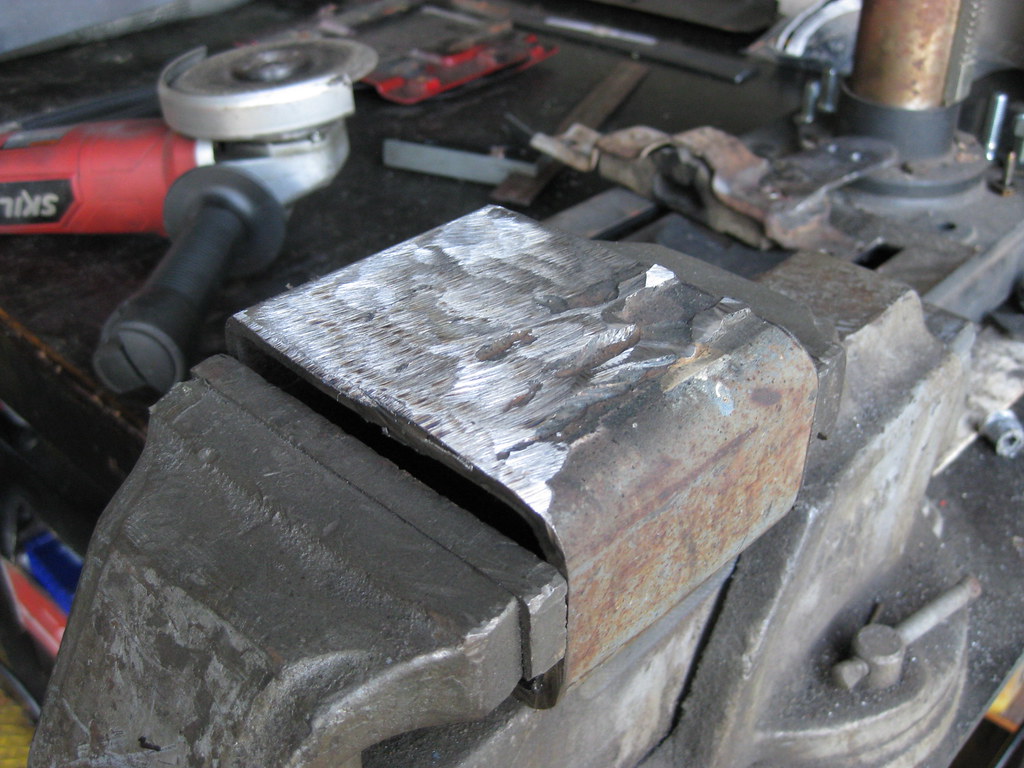
I ended up with these two pieces.
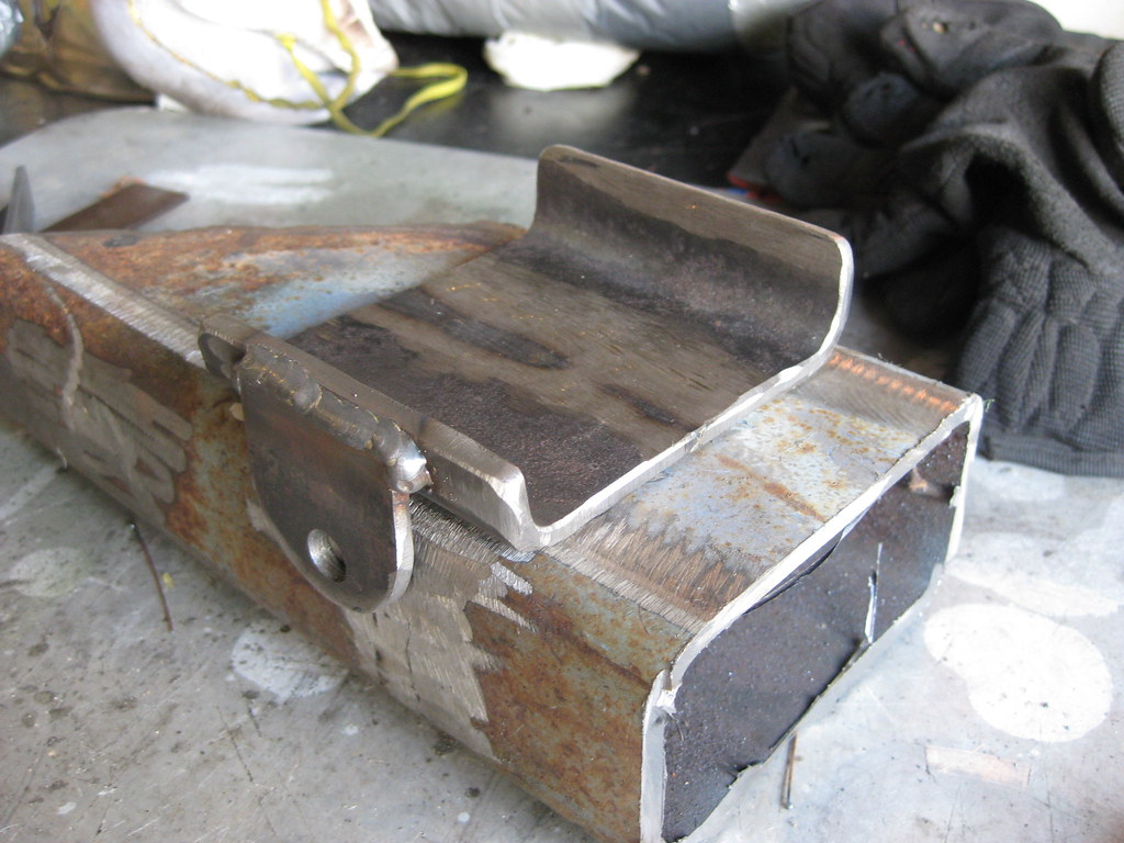
 Several years ago I got some inner-tubes from a dump truck tire to use for a project. I plan to use these again to insulate the steel on the bottom mounts from touching the aluminum on the radiator. Aside from providing a cushion, the rubber will prevent the two dissimilar metals from reacting with one another.
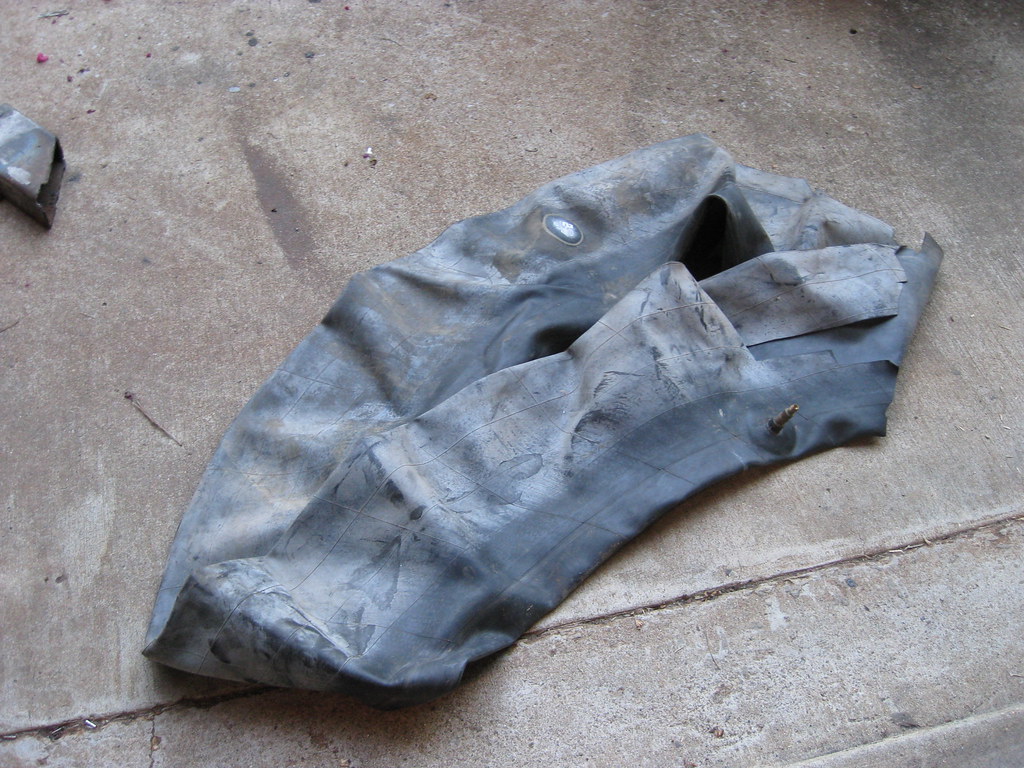 The first test fitting revealed that the length of the bracket was just a bit too large. I could have made it work by adding more pieces of rubber, as shown below, but after thinking it over I realized this was not the correct way to fix the problem and I needed to make it right. The size pictured below would require 4 pieces of rubber, with one piece being cut long and folder over on itself on each end in order to secure the radiator with no movement or play.
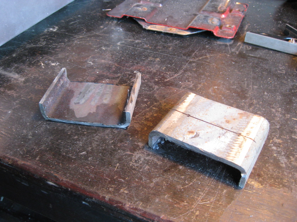
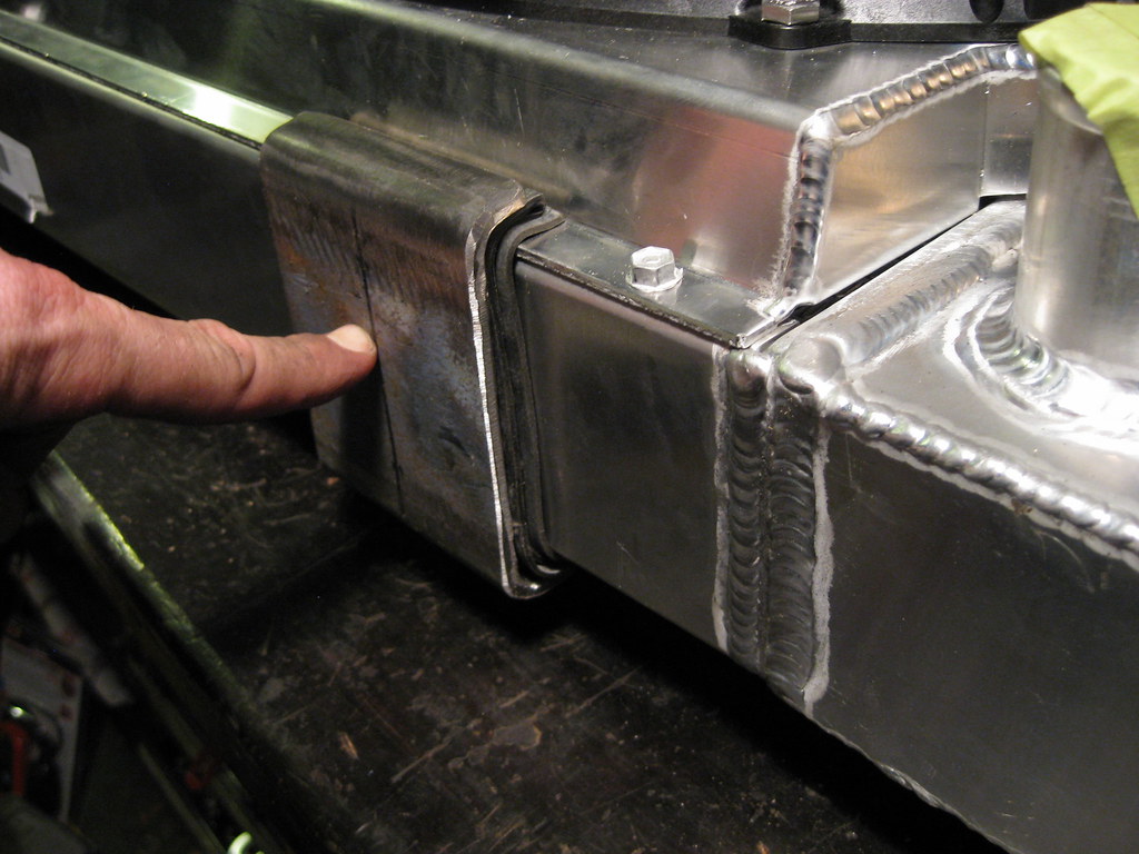
I had to cut almost this much out of the middle of the bracket.
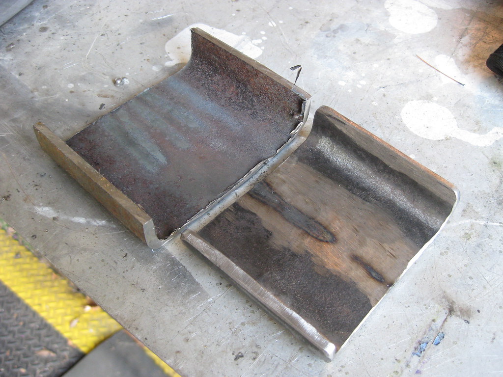
This is a much better and more secure fit, leaving enough room for two pieces of rubber.
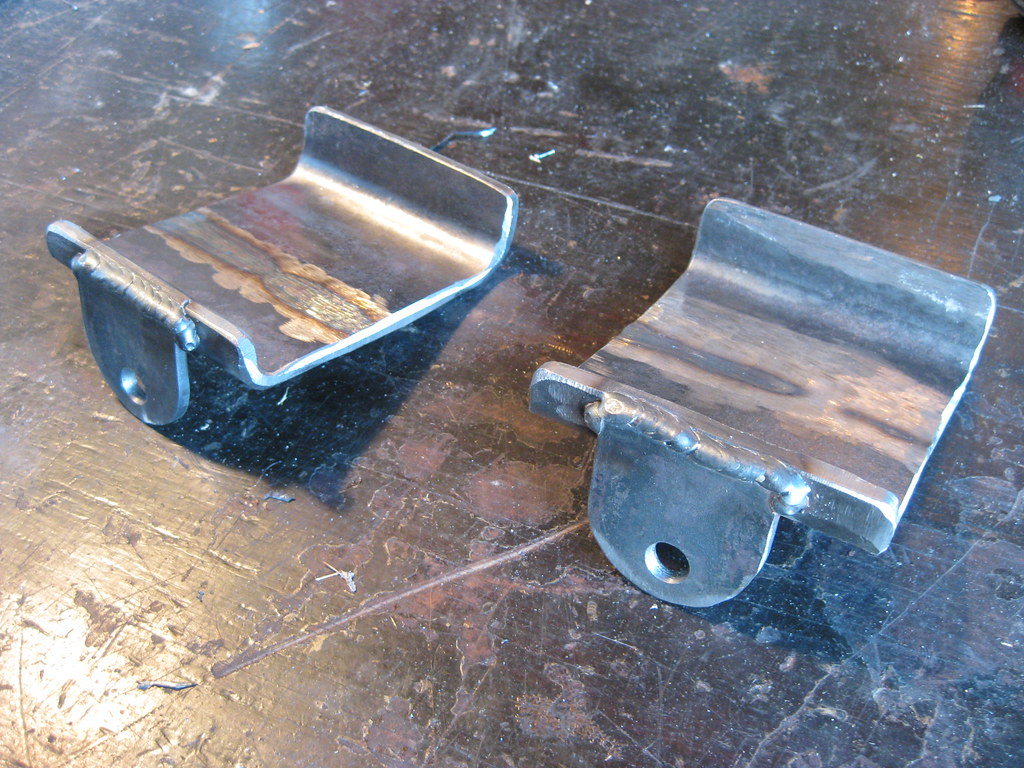
The second piece went quicker because I could use the first as a template.
After a lot more test fitting, grinding and drilling, this was the finished result of the new bracket shape.
After finishing the other one all that will be left is primer, paint and gluing the rubber into the mounts.
Then I moved on to the top. I thought I had stored these rubber insulators from a previous project with some other parts in my dad's barn loft. After going over there and searching everywhere I found they had been less than 5 feet from me the whole time in my garage.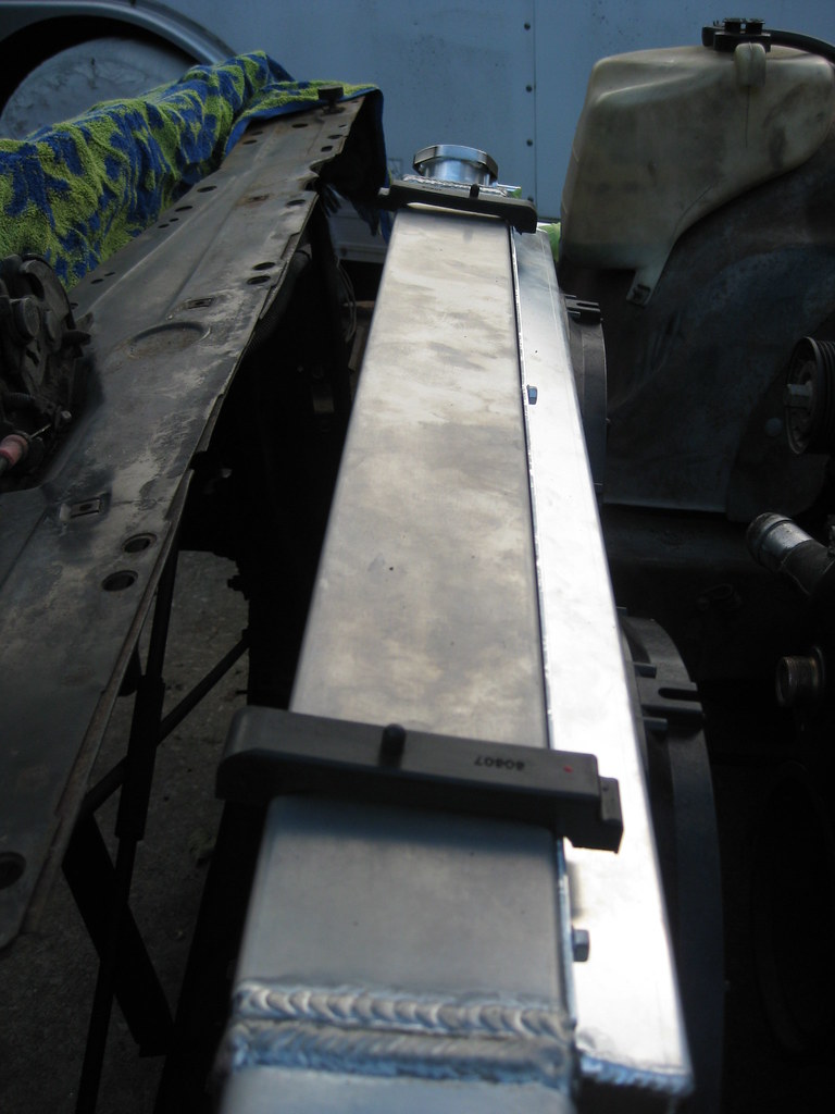
After considering several different types of bracket options for the top I made a rough cardboard template to get an idea of what kinds of bends I would need and to see if I would like the overall shape. My next step will be to try to find someone that will let me use a metal break.
I removed the old exhaust hanger so that I could add a mounting bracket for the fuel lines.
After after a lot of grinding dust, it looked like this. I will paint this and all of the other parts at one time when I have them finished.It was time to make the mounting brackets for the radiator. This part was particularly difficult for me to wrap my head around. There seem to be as many ways to mount a radiator as there are people, however I wanted to do it correctly. I tend to believe that if the frame flexes under torsion then hard-mounting the radiator would put undue stress on the aluminum welds of the piece. I wanted to dampen the radiator with rubber mounts as the automobile manufacturers do.
I scrounged through my scrap metal pile and found this piece. This was the very first piece of scrap metal I got at the scrapyard when I first got my welder to use for practice. I had probably cut this thing in half and put it back together 3 or 4 times, as well as laid a lot of beads on top of it. It was pretty close to the right shape and size to make bottom radiator supports.
I made some measurements and started burning through some grinding wheels.
I had a lot of grinding to do to smooth out all of the old practice beads I had put down.
I ended up with these two pieces.
Several years ago I got some inner-tubes from a dump truck tire to use for a project. I plan to use these again to insulate the steel on the bottom mounts from touching the aluminum on the radiator. Aside from providing a cushion, the rubber will prevent the two dissimilar metals from reacting with one another.The first test fitting revealed that the length of the bracket was just a bit too large. I could have made it work by adding more pieces of rubber, as shown below, but after thinking it over I realized this was not the correct way to fix the problem and I needed to make it right. The size pictured below would require 4 pieces of rubber, with one piece being cut long and folder over on itself on each end in order to secure the radiator with no movement or play.I had to cut almost this much out of the middle of the bracket.
This is a much better and more secure fit, leaving enough room for two pieces of rubber.
The second piece went quicker because I could use the first as a template.
After a lot more test fitting, grinding and drilling, this was the finished result of the new bracket shape.
After finishing the other one all that will be left is primer, paint and gluing the rubber into the mounts.
Then I moved on to the top. I thought I had stored these rubber insulators from a previous project with some other parts in my dad's barn loft. After going over there and searching everywhere I found they had been less than 5 feet from me the whole time in my garage.
After considering several different types of bracket options for the top I made a rough cardboard template to get an idea of what kinds of bends I would need and to see if I would like the overall shape. My next step will be to try to find someone that will let me use a metal break.
07-28-2018, 11:38 PM
#38
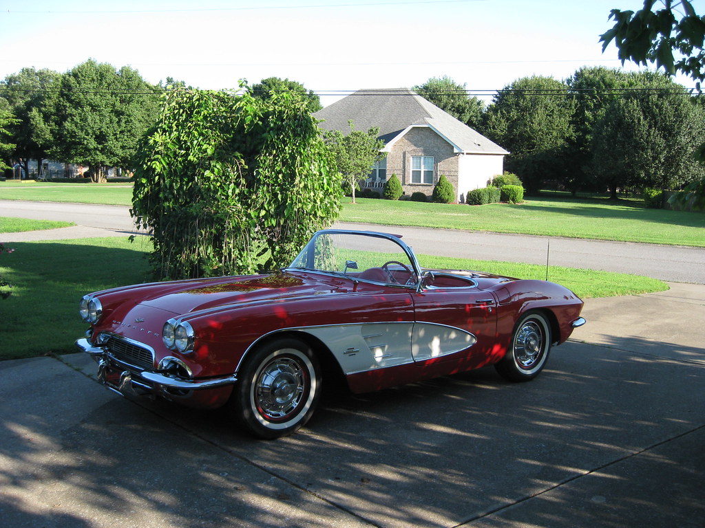
Dad stopped by with Little Red. It's the first time it has been driven in a very long time. Last year it wouldn't start, which turned out to be a fuel pump, so while he was gone during the winter I put a new fuel pump on it. When he tried to drive it a couple weeks ago it would drive for a short while and then sputter and die. It seems to have just been the fuel filter, which on this car is a small filter that fits into a housing on the carburetor. The old filter appeared to have something melted inside of it. My best guess, which is a long shot, is that the old diaphram broke apart and got stuck in the filter and then melted. He made it over to the house one day last week and it barely made it home. On this trip it didn't give any troubles.This car has had the 283 replaced with a 327 bored .30 over and has a small cam. The air filter fitment has always been pretty finicky and after looking closer I realized that if you positioned it so that the throttle didn't hit the base plate when your foot was off the throttle, then it would hit when you pressed the pedal. If you adjusted it so it wouldn't hit when you hit the gas, then it would make contact with the base plate of the filter when you didn't touch the pedal. We marked and modified the base plate and got the throttle working with no contact with the air cleaner base plate.
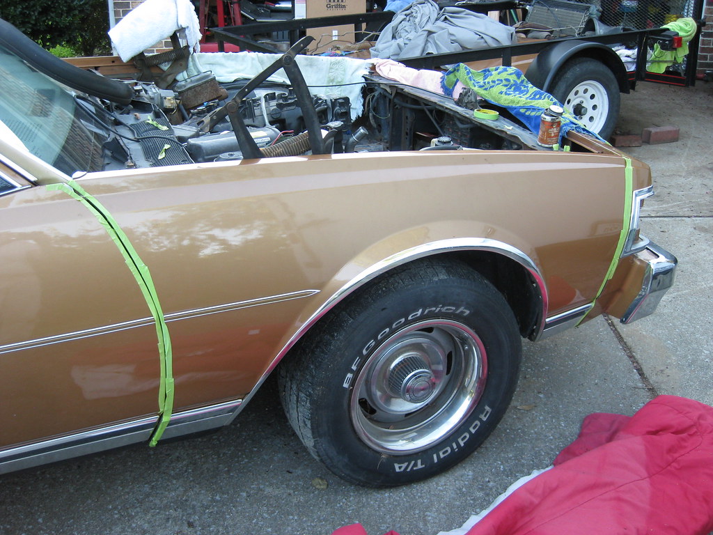
I put the passenger side fender back on. Working on the car would have been easier if I left the fender off, however covering the car continually with a tarp was a bigger hassle than it was worth. This is where all of the previous labeling came in very handy.
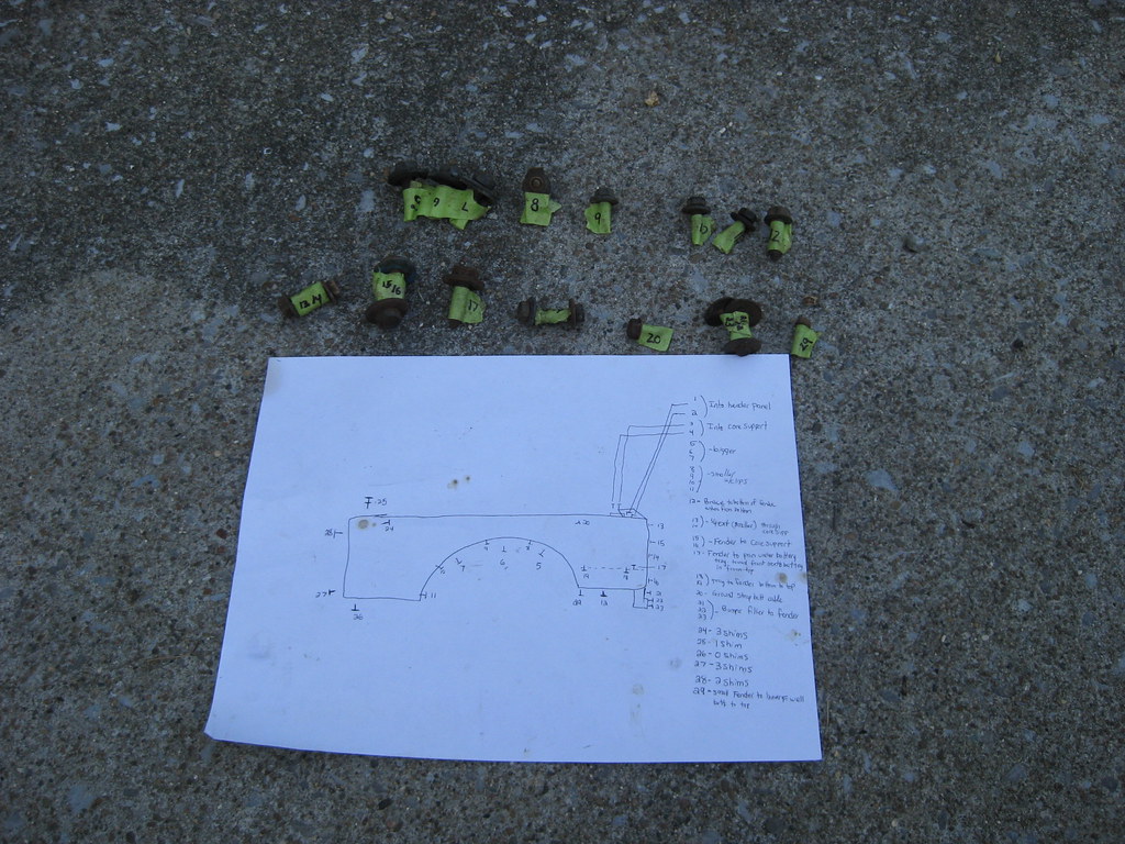
It's always easy to let imperfections slide in the alignment of panels because the factory didn't even align the panels correct back in the 70's.
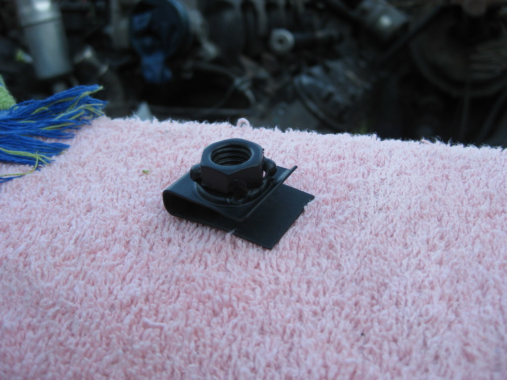
This clip fell out of the fender when I took it off. It was rusted and the nut was stripped out so I welded the nut back on, cleaned it and painted it. Then I found out it doesn't go anywhere. All of the bolt holes had bolts and clips.
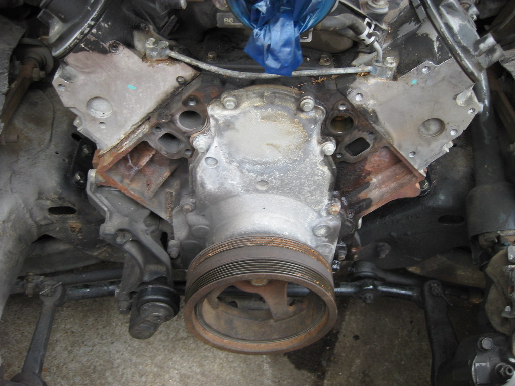
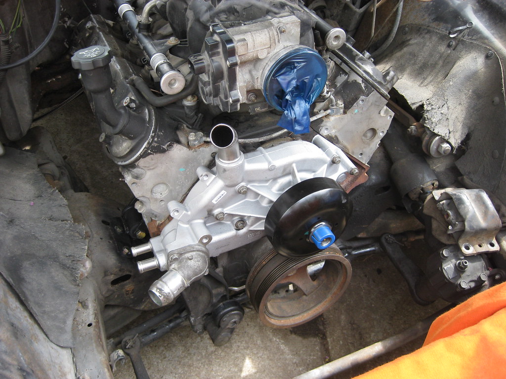
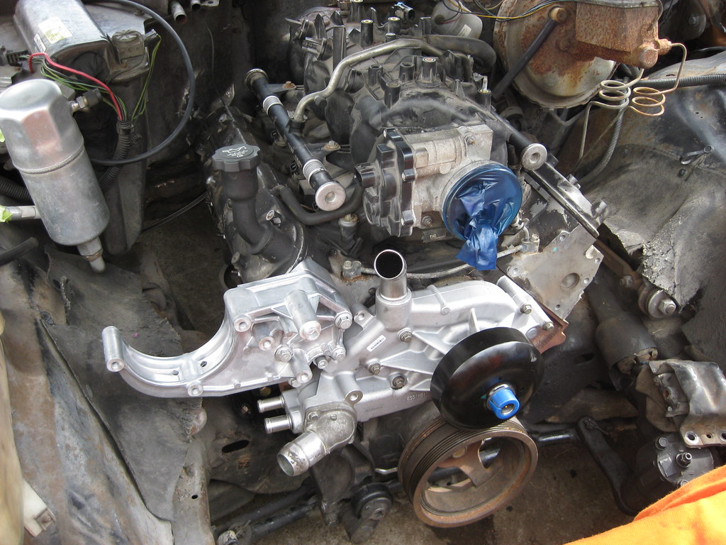
I took the old water pump off. I'm not sure if it was bad, but I didn't want to find out. It is a true test of discipline to not over-restore this project. The temptation to clean, paint and restore everything is enormous, but this is a daily driver that needs to be finished quickly without snowballing into a 6 month project. I really want to paint the block, powdercoat the inner fenders, and make the entire engine bay look brand new.
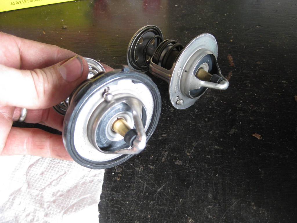
The instructions for the new thermostat were somewhat confusing. There are two types of gaskets to use depending on what type of housing you have. The instructions said to use a paper gasket for my type of housing, but the housing didn't have a gasket at all when I took it apart. Also, the new thermostat didn't have this piece of rubber around the outer perimeter so I had to reuse the old one from the old thermostat. Pictured below is the new thermostat with the old rubber gasket attached.
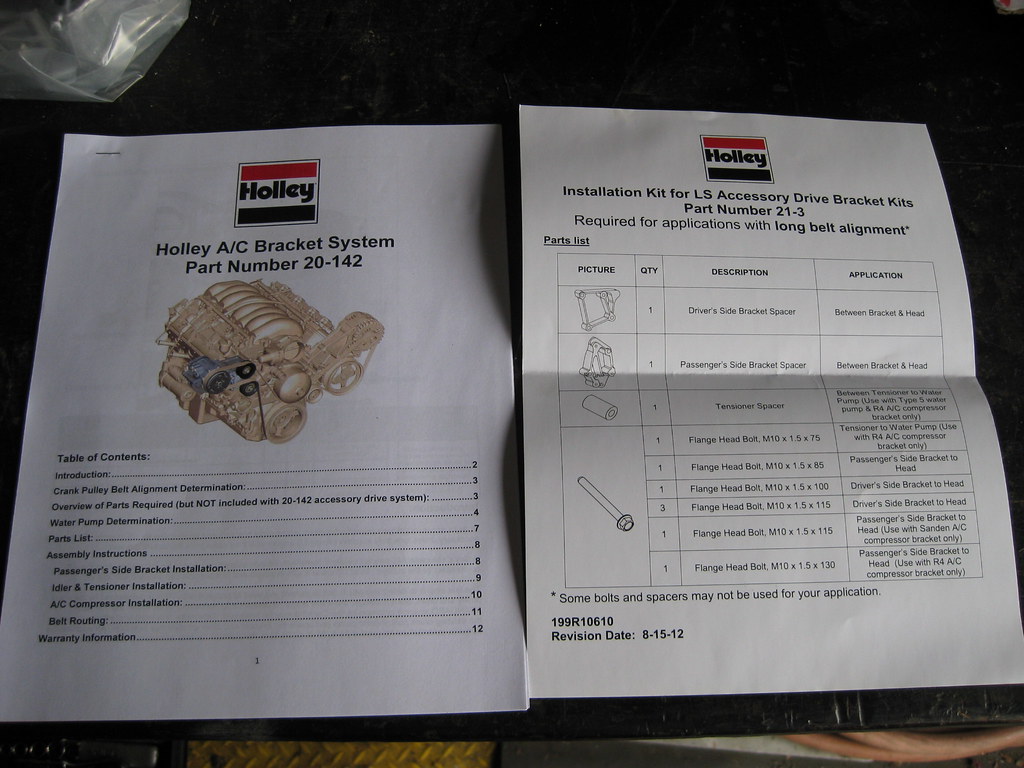
I opened up the Holley high mount AC bracket kit. The packing was top notch.
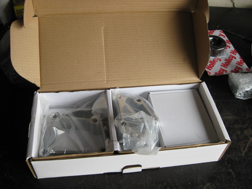
The instructions were much better than what I've been used to seeing from some of these "so called" LS Swap kits.
The new pump went on without too much of a hassle except for the fact that I got it torqued down and realized I forgot to put the gaskets in place. Since gaskets are fairly important I got to install the water pump twice.
The worst part about the Holley kit was that I found they included bolts and brackets for all 3 types of kits they offer, which meant that I had to find out which bolts went with my kit and which bolts weren't needed. Perhaps someone better at following instructions than myself wouldn't have had trouble, but it was a bit confusing. Either way, the kit was very nice and fit as described. Nice fit, nice finish and an overall well designed product, which is something I've grown unaccustomed to with the other kit's I've used so far.
I put the passenger side fender back on. Working on the car would have been easier if I left the fender off, however covering the car continually with a tarp was a bigger hassle than it was worth. This is where all of the previous labeling came in very handy.
It's always easy to let imperfections slide in the alignment of panels because the factory didn't even align the panels correct back in the 70's.
This clip fell out of the fender when I took it off. It was rusted and the nut was stripped out so I welded the nut back on, cleaned it and painted it. Then I found out it doesn't go anywhere. All of the bolt holes had bolts and clips.
I took the old water pump off. I'm not sure if it was bad, but I didn't want to find out. It is a true test of discipline to not over-restore this project. The temptation to clean, paint and restore everything is enormous, but this is a daily driver that needs to be finished quickly without snowballing into a 6 month project. I really want to paint the block, powdercoat the inner fenders, and make the entire engine bay look brand new.
The instructions for the new thermostat were somewhat confusing. There are two types of gaskets to use depending on what type of housing you have. The instructions said to use a paper gasket for my type of housing, but the housing didn't have a gasket at all when I took it apart. Also, the new thermostat didn't have this piece of rubber around the outer perimeter so I had to reuse the old one from the old thermostat. Pictured below is the new thermostat with the old rubber gasket attached.
I opened up the Holley high mount AC bracket kit. The packing was top notch.
The instructions were much better than what I've been used to seeing from some of these "so called" LS Swap kits.
The new pump went on without too much of a hassle except for the fact that I got it torqued down and realized I forgot to put the gaskets in place. Since gaskets are fairly important I got to install the water pump twice.
The worst part about the Holley kit was that I found they included bolts and brackets for all 3 types of kits they offer, which meant that I had to find out which bolts went with my kit and which bolts weren't needed. Perhaps someone better at following instructions than myself wouldn't have had trouble, but it was a bit confusing. Either way, the kit was very nice and fit as described. Nice fit, nice finish and an overall well designed product, which is something I've grown unaccustomed to with the other kit's I've used so far.
07-28-2018, 11:38 PM
#39
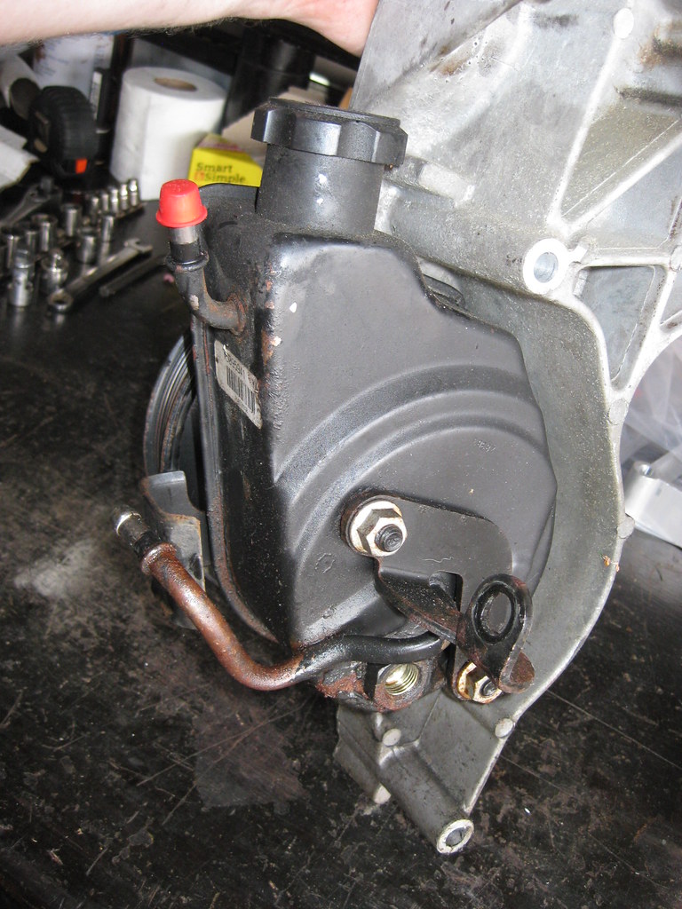
I'm going to need to adapt the power steering pump to The Caprice's gearbox. I'm not sure what the 3 fittings are for just yet. There's two lines and a fitting at the bottom of the pump.
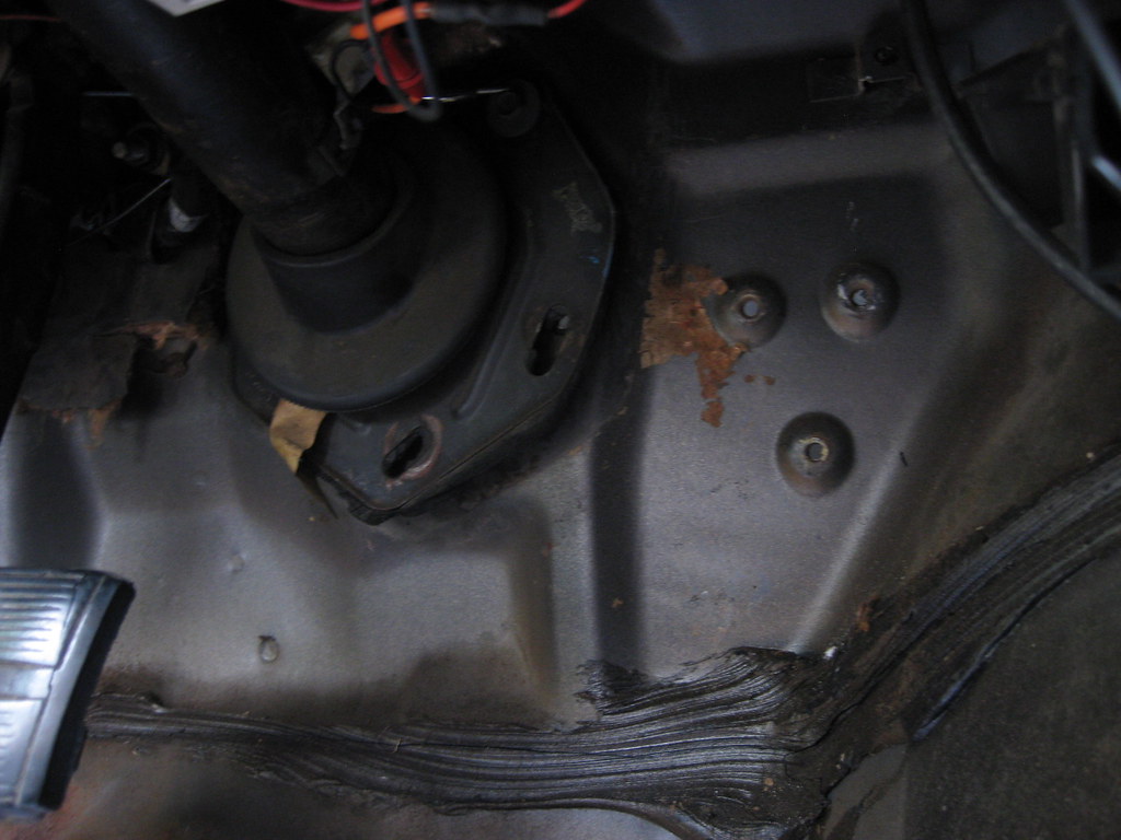
I started working on getting the new pedal mounted. This is the area I have to work with. The three humps below are where the old gas pedal assembly mounted. Because the firewall is not flat in this area and I also don't want to drill more holes in the firewall, the solution I came up with is to make a plate that will bolt to the original holes and then mount the new pedal assembly to the plate. I used a piece of paper to get a rough shape and then transferred that to cardboard.
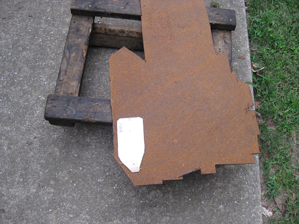
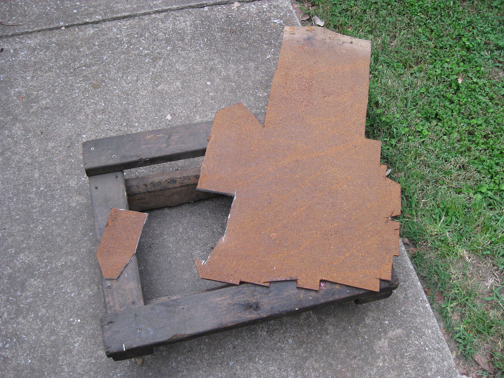
I got out the giant piece of 1/4 steel I got years ago at the scrapyard for practically no money. I've made all kinds of car parts out of this piece of steel and it's still bearing fruit. I was fortunate and found one of the existing sides already matched one of the angles I had made with the template.
This finished up yet another grinding wheel.
After lots of trips back and forth between the table and laying in the floorboard the final product slowly began to take shape.
The tricky part was transferring the hole pattern to the piece of steel plate. I was not able to fit a pen through the holes to mark the plate and I also didn't have anyone to hold the plate for me while I marked it even if I could. I taped a piece of cardboard to the firewall and marked the hole pattern from inside the car.
I then measured and drilled the first hole.
I used the first hole to hold the plate in it's location and left it loose enough to adjust back and forth until I had it positioned in just the right place. Then I used white fingernail polish on the back of the plate. I was able to get a small, pointed pick through one of the holes in the firewall and score the location on the white fingernail polish.
I then used the old pedal assembly to align the markings. I had to have the plate mounted in the car to get it clocked in the right position. After that I used the two holes to locate the 3rd hole and drilled it as well. I was tired at the end of the night I forgot to take a picture of the last step I got done for the night. The final plan will be to use small spacers between the firewall and plate and also spacers between the pedal assembly and plate, which will allow room for the nuts and bolts from each piece to fit.
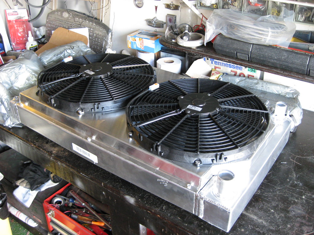
After doing some research and getting a lot of opinions I decided to try to return the radiator which did not have a transmission cooler built in. It seems that the transmission cooler also heats the transmission fluid when it is cold causing the transmission to get up to temperature sooner which allows longevity of life of the unit. After considering this and the amount of fabrication it was going to take to get an external transmission cooler to fit in the limited space I have I decided to try if I could swap out the radiator. Fortunately, because of the Holley debacle with the AC compressor I had established a relationship with a tech support at the vendor so I called that extension and they worked with me. I hadn't installed the radiator, other than just sitting it in the car to measure for mounts, so I was able to return it. I am currently awaiting the new radiator. I also painted the bottom radiator mounts but will have to wait for the new radiator to get here before I know exactly how many layers of rubber to glue to the bottom. I had to do two oil change and tire rotations and get some personal business done today so I was yet again unable to make it to the scrapyard to try to find some metal for the upper radiator mount.
I started working on getting the new pedal mounted. This is the area I have to work with. The three humps below are where the old gas pedal assembly mounted. Because the firewall is not flat in this area and I also don't want to drill more holes in the firewall, the solution I came up with is to make a plate that will bolt to the original holes and then mount the new pedal assembly to the plate. I used a piece of paper to get a rough shape and then transferred that to cardboard.
I got out the giant piece of 1/4 steel I got years ago at the scrapyard for practically no money. I've made all kinds of car parts out of this piece of steel and it's still bearing fruit. I was fortunate and found one of the existing sides already matched one of the angles I had made with the template.
This finished up yet another grinding wheel.
After lots of trips back and forth between the table and laying in the floorboard the final product slowly began to take shape.
The tricky part was transferring the hole pattern to the piece of steel plate. I was not able to fit a pen through the holes to mark the plate and I also didn't have anyone to hold the plate for me while I marked it even if I could. I taped a piece of cardboard to the firewall and marked the hole pattern from inside the car.
I then measured and drilled the first hole.
I used the first hole to hold the plate in it's location and left it loose enough to adjust back and forth until I had it positioned in just the right place. Then I used white fingernail polish on the back of the plate. I was able to get a small, pointed pick through one of the holes in the firewall and score the location on the white fingernail polish.
I then used the old pedal assembly to align the markings. I had to have the plate mounted in the car to get it clocked in the right position. After that I used the two holes to locate the 3rd hole and drilled it as well. I was tired at the end of the night I forgot to take a picture of the last step I got done for the night. The final plan will be to use small spacers between the firewall and plate and also spacers between the pedal assembly and plate, which will allow room for the nuts and bolts from each piece to fit.
After doing some research and getting a lot of opinions I decided to try to return the radiator which did not have a transmission cooler built in. It seems that the transmission cooler also heats the transmission fluid when it is cold causing the transmission to get up to temperature sooner which allows longevity of life of the unit. After considering this and the amount of fabrication it was going to take to get an external transmission cooler to fit in the limited space I have I decided to try if I could swap out the radiator. Fortunately, because of the Holley debacle with the AC compressor I had established a relationship with a tech support at the vendor so I called that extension and they worked with me. I hadn't installed the radiator, other than just sitting it in the car to measure for mounts, so I was able to return it. I am currently awaiting the new radiator. I also painted the bottom radiator mounts but will have to wait for the new radiator to get here before I know exactly how many layers of rubber to glue to the bottom. I had to do two oil change and tire rotations and get some personal business done today so I was yet again unable to make it to the scrapyard to try to find some metal for the upper radiator mount.
07-29-2018, 10:17 AM
#40
TECH Senior Member
iTrader: (7)
The fitting at the bottom of the pump is the high pressure feed to the steering box. The other two fittings, with the nipples, are both return lines. One is the low pressure return from the steering box and the other was probably a return line from a hydro boost brake system.
Andrew
Andrew