
1978 Aerocoupe Caprice: 5.3 / 4L60E

 08-17-2018, 11:34 AM
#63
Staging Lane
Join Date: Jun 2016
Posts: 68
Likes: 0
Received 0 Likes
on
0 Posts

 08-20-2018, 09:45 PM
#64
oh man, where were you a month ago??? Haha, I wish you could see how much grief we had trying to souse that engine and trans in there with an FBody oil pan. I think we should probably get some sort of gold metal because we actually got it in there, but it of course wouldn't go forward enough to let the motor mounts line up.
08-21-2018, 11:05 AM
#65
Staging Lane
Join Date: Jun 2016
Posts: 68
Likes: 0
Received 0 Likes
on
0 Posts
oh man, where were you a month ago??? Haha, I wish you could see how much grief we had trying to souse that engine and trans in there with an FBody oil pan. I think we should probably get some sort of gold metal because we actually got it in there, but it of course wouldn't go forward enough to let the motor mounts line up.
08-24-2018, 11:50 PM
#66
I have spent a tremendous amount of the little time I have researching things online, but I don't have a lot of pictures to show for it. The investment of new neuron connections seem to be something that is only evident in future payoffs. I've just been having to spend 10 minutes here or 5 minutes there during the week and then stay up late and try to read as much as I can from the internet about what steps to take next. These 18 and 19 hour days are getting tiresome but the end is in sight.
I found out my PCM does not have the correct hardware which would allow my air conditioner setup to be operated by the PCM in the way that I would like it to, so I'm going to have to get a different one. This project is so far over budget at this point it feels like telling the surgeon amputating a gangrenous toe to go ahead and take the pelvis.
I haven't been able to find any steel the size I need to make the upper radiator mount. I have been scrounging through the scrap piles of local body shops and the scrapyard trying to find something I could use. Most of the metal on cars today is so thin it's barely able to be used as panels on cars, least of all structural support. If I had a bead-roller it would open up a lot of doors to make thinner metal sturdier. I did end up getting the quarter panel below from a Tahoe or Suburban. I'll use this, somehow, to make the air dams that will keep the air from bypassing the condenser and radiator. I haven't figured that part out yet, but I know it has to be done, so I'll have to make it works somehow.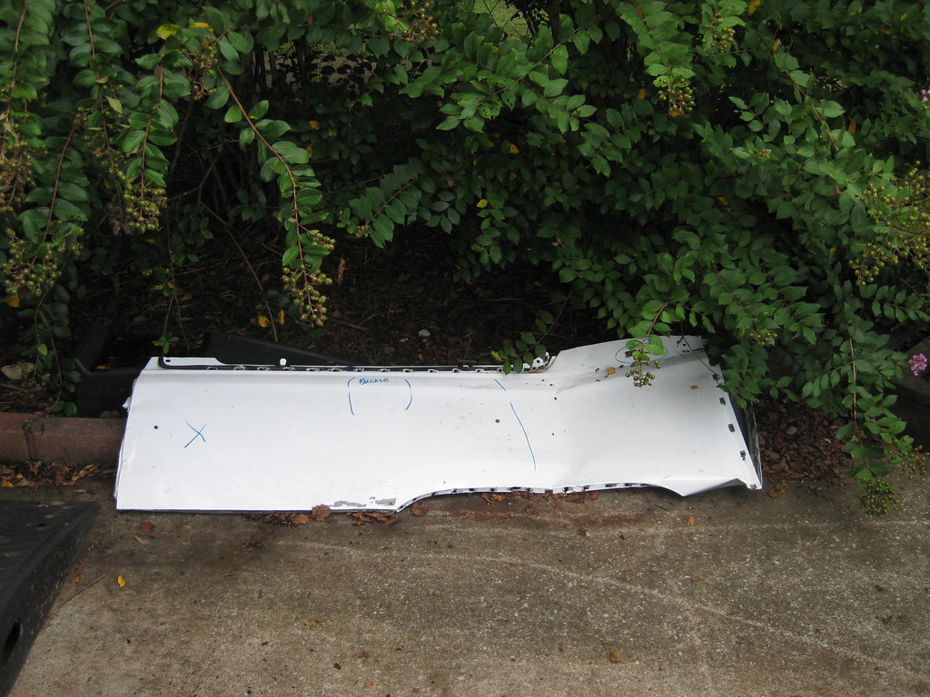
I finally got tired of people flaking out about manifolds and just bought a set of 5th generation Camaro manifolds, hoping they would fit. The set I bought looked pretty rough in the pictures, but the person I bought them from was nice enough to sand blast them before shipping them. I sanded them down further and prepped them for paint.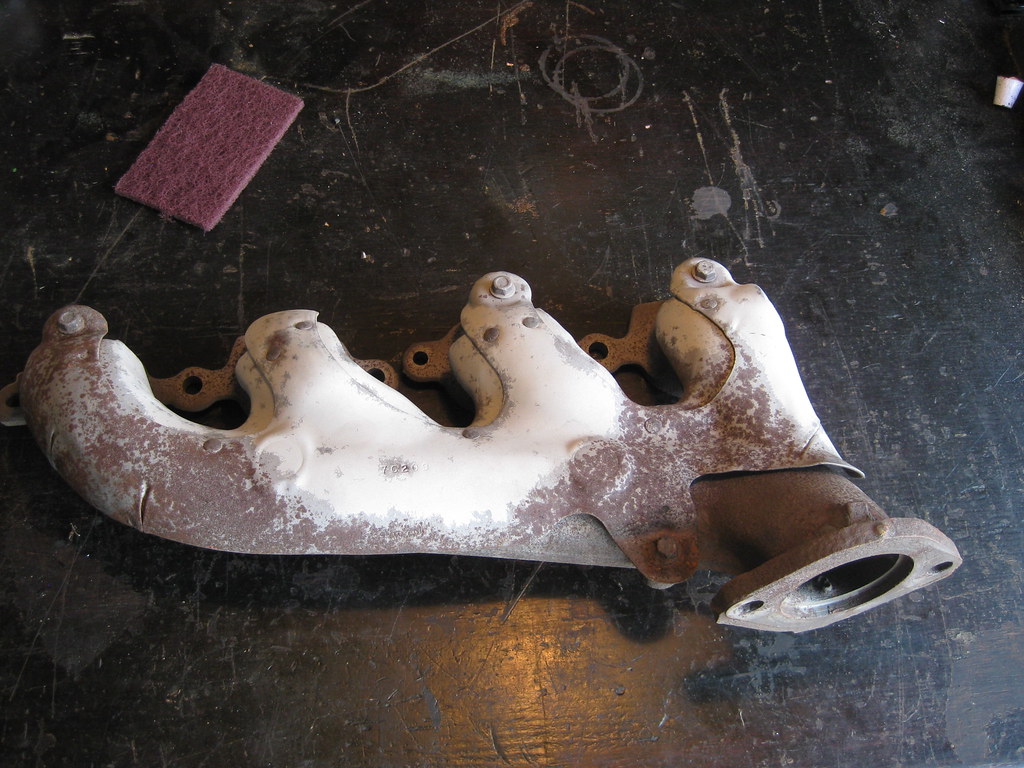
Header paint is expensive. That's all I've got to say about that. I had originally planned to paint the heat shields silver to more closely match what they originally looked like, but I already had this cast grey in the heat resistant paint so I used it. I was surprised to find that I actually like this color combination better. It's a bit more low key and blends in better with the crusty looking engine and engine bay. I was not about to try to remove the head shields and deal with all the broken bolts so I had to tape everything off, which took a long time. It kept springing up summer showers while I was trying to paint, so that also delayed things.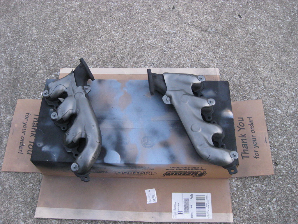
I painted the manifolds black because I figured they would blend in better as they aged. I ended up putting on two coats of "very high heat" resistant primer, two coats of basecoat and two coats of clear coat. I'm not sure, but I hope that will prolong the typical manifold paint flaking that always takes place. Or maybe the paint will be too thick and it'll all fall off. Only time will tell. I coated the inside of the tubes as well at the advice of someone I met in the store buying the paint. Maybe it will help cut down on the heat and paint flaking, or maybe not. Again, I didn't figure it would hurt anything and time will tell.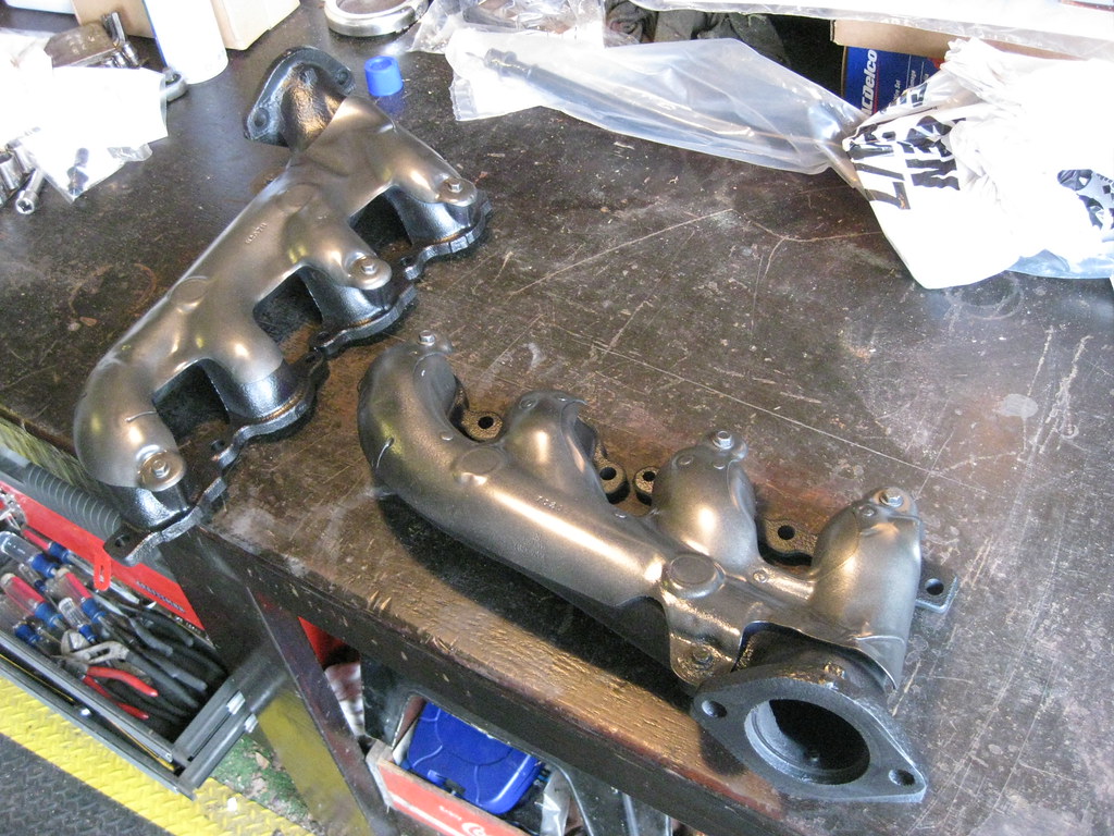
I got a lot of small things mounted like the evap solenoid block off plate, the coils, new spark plugs and coil wires, the exhaust manifolds, the starter, etc. One of my new plug wires was bad so I've had to order a single one from the dealer. They must be made out of gold. $$$.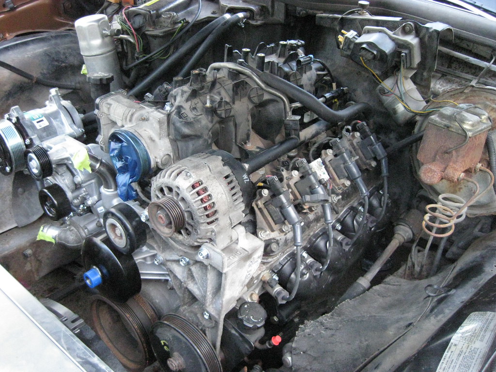
The exhaust manifold on the driver side fits great.
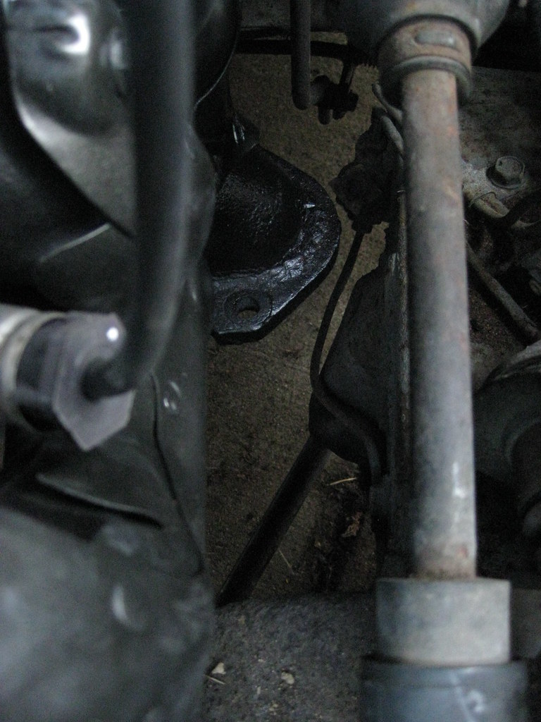
The passenger side is either touching the frame, or it's so close it would have to be measured in microns. I'm not sure how much of this flange I can grind off without effecting the way the exhaust will mount together, so I'm going to let the exhaust shop handle this to their liking.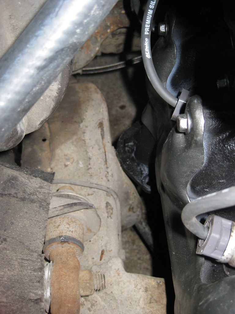
One great thing about having a father that's retired is he can run and get parts during normal business hours. Dad dropped off my transmission yoke at the driveshaft shop and then picked it up when they had made a new driveshaft to my specifications.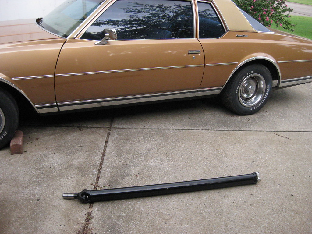
I think I jacked the car up and took this measurement around 5 times, on 5 different days. Each time I would think I had the measurement taken in the correct way and then I would learn something new that made me realize I needed to remeasure or double check what I had done. I installed the driveshaft holding my breath and it fit exactly right. Relief.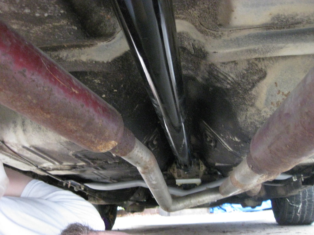
The yoke had just the right about of run out. Now I just hope the BRP transmission mount got the driveline angle correct, as it was advertised to do. My experience with the rest of their products on this car has left me less than confident.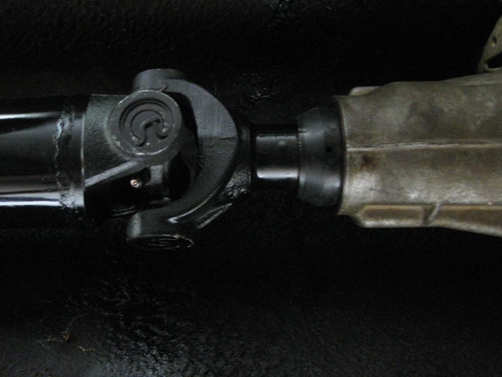
I bought an oil filter for a 2004 Avalanche, because that's what kind of engine I have in the car. I got home, filled it full of oil and realized, I have a 2004 Avalanche engine in my car, but the oil pan for that engine is now sitting in a barn. I have a Holley oil pan on the engine. So I gave the oil filter to dad for his next oil change on his Suburban and bought the correct oil filter, a PF48. When I went to install the oil filter it suddenly occurred to me that there's nothing to screw it to. Go back in time to earlier in this story and I purchased the Holley oil pan, which comes with two provisions for turbos, if one were so included to add them. I'm not using turbos so I plugged the holes with the provided plugs. I had assumed at that time, without thinking, that the piece pictured below was an adapter for a turbo. Fast forward to me looking at the oil pan like a calf at a dried up sow and I immediately realized that piece was the oil filter adapter, but where had I put it? At this point my entire garage looks like that jar of loose screws and nuts that old men always have in their shop and I had no idea where I had put this thing. Was it in one of the boxes I'd stored in the barns far away? Was it in dad's barn? Was it in some random box in my garage? I had no idea. I ruminated on this for quite a while and finally gave up and as so often happens when you have succumb to defeat, suddenly it occurred to me that I thought I had wrapped this piece up and put it in a storage pin sitting over my workbench. When I looked, it was right where I thought it might be. What a relief. 40 foot pounds later (and 1/4 turn past hand tight on the filter), I had an oil filter on the car.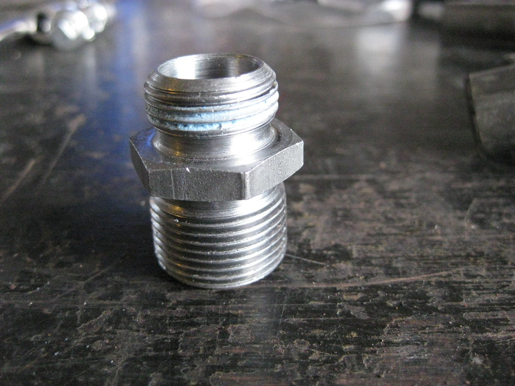
My childrens' babysitter called in late last night with a stomach bug so I had to take off work and keep them. I used this time to take a field trip to the steel supply store in Nashville and picked up two pieces of 1/8" steel, which they cut to my specifications. Unfortunately, they didn't have a metal brake. I'll use one of these two pieces for the upper radiator mount. I'm still not sure how I'm going to get the piece bent into shape, but at least I have the steel now. The other piece will be a mount for the PCM and new fusebox.
I spent a ridiculous amount of time reading about what kind of fusebox I would want to order for my needs for this car. There is so much information it is entirely overwhelming. Fortunately I found a superb write up online about this very topic. I printed out every page of the write up and put it in a 3-ring binder and have been using it like an encyclopedia for a pre-internet research final due at 8:00 am tomorrow. I was up past midnight one night trying to figure out all the correct connectors and pieces I would need to order and how they would fit together. After looking at my options I have decided on a way to mount the PCM that I believe will not only be the cleanest appearing installation, but may also still allow me to run the air filter over to the driver side of the engine.
I found out my PCM does not have the correct hardware which would allow my air conditioner setup to be operated by the PCM in the way that I would like it to, so I'm going to have to get a different one. This project is so far over budget at this point it feels like telling the surgeon amputating a gangrenous toe to go ahead and take the pelvis.
I haven't been able to find any steel the size I need to make the upper radiator mount. I have been scrounging through the scrap piles of local body shops and the scrapyard trying to find something I could use. Most of the metal on cars today is so thin it's barely able to be used as panels on cars, least of all structural support. If I had a bead-roller it would open up a lot of doors to make thinner metal sturdier. I did end up getting the quarter panel below from a Tahoe or Suburban. I'll use this, somehow, to make the air dams that will keep the air from bypassing the condenser and radiator. I haven't figured that part out yet, but I know it has to be done, so I'll have to make it works somehow.
I finally got tired of people flaking out about manifolds and just bought a set of 5th generation Camaro manifolds, hoping they would fit. The set I bought looked pretty rough in the pictures, but the person I bought them from was nice enough to sand blast them before shipping them. I sanded them down further and prepped them for paint.
Header paint is expensive. That's all I've got to say about that. I had originally planned to paint the heat shields silver to more closely match what they originally looked like, but I already had this cast grey in the heat resistant paint so I used it. I was surprised to find that I actually like this color combination better. It's a bit more low key and blends in better with the crusty looking engine and engine bay. I was not about to try to remove the head shields and deal with all the broken bolts so I had to tape everything off, which took a long time. It kept springing up summer showers while I was trying to paint, so that also delayed things.
I painted the manifolds black because I figured they would blend in better as they aged. I ended up putting on two coats of "very high heat" resistant primer, two coats of basecoat and two coats of clear coat. I'm not sure, but I hope that will prolong the typical manifold paint flaking that always takes place. Or maybe the paint will be too thick and it'll all fall off. Only time will tell. I coated the inside of the tubes as well at the advice of someone I met in the store buying the paint. Maybe it will help cut down on the heat and paint flaking, or maybe not. Again, I didn't figure it would hurt anything and time will tell.
I got a lot of small things mounted like the evap solenoid block off plate, the coils, new spark plugs and coil wires, the exhaust manifolds, the starter, etc. One of my new plug wires was bad so I've had to order a single one from the dealer. They must be made out of gold. $$$.
The exhaust manifold on the driver side fits great.
The passenger side is either touching the frame, or it's so close it would have to be measured in microns. I'm not sure how much of this flange I can grind off without effecting the way the exhaust will mount together, so I'm going to let the exhaust shop handle this to their liking.
One great thing about having a father that's retired is he can run and get parts during normal business hours. Dad dropped off my transmission yoke at the driveshaft shop and then picked it up when they had made a new driveshaft to my specifications.
I think I jacked the car up and took this measurement around 5 times, on 5 different days. Each time I would think I had the measurement taken in the correct way and then I would learn something new that made me realize I needed to remeasure or double check what I had done. I installed the driveshaft holding my breath and it fit exactly right. Relief.
The yoke had just the right about of run out. Now I just hope the BRP transmission mount got the driveline angle correct, as it was advertised to do. My experience with the rest of their products on this car has left me less than confident.
I bought an oil filter for a 2004 Avalanche, because that's what kind of engine I have in the car. I got home, filled it full of oil and realized, I have a 2004 Avalanche engine in my car, but the oil pan for that engine is now sitting in a barn. I have a Holley oil pan on the engine. So I gave the oil filter to dad for his next oil change on his Suburban and bought the correct oil filter, a PF48. When I went to install the oil filter it suddenly occurred to me that there's nothing to screw it to. Go back in time to earlier in this story and I purchased the Holley oil pan, which comes with two provisions for turbos, if one were so included to add them. I'm not using turbos so I plugged the holes with the provided plugs. I had assumed at that time, without thinking, that the piece pictured below was an adapter for a turbo. Fast forward to me looking at the oil pan like a calf at a dried up sow and I immediately realized that piece was the oil filter adapter, but where had I put it? At this point my entire garage looks like that jar of loose screws and nuts that old men always have in their shop and I had no idea where I had put this thing. Was it in one of the boxes I'd stored in the barns far away? Was it in dad's barn? Was it in some random box in my garage? I had no idea. I ruminated on this for quite a while and finally gave up and as so often happens when you have succumb to defeat, suddenly it occurred to me that I thought I had wrapped this piece up and put it in a storage pin sitting over my workbench. When I looked, it was right where I thought it might be. What a relief. 40 foot pounds later (and 1/4 turn past hand tight on the filter), I had an oil filter on the car.
My childrens' babysitter called in late last night with a stomach bug so I had to take off work and keep them. I used this time to take a field trip to the steel supply store in Nashville and picked up two pieces of 1/8" steel, which they cut to my specifications. Unfortunately, they didn't have a metal brake. I'll use one of these two pieces for the upper radiator mount. I'm still not sure how I'm going to get the piece bent into shape, but at least I have the steel now. The other piece will be a mount for the PCM and new fusebox.
I spent a ridiculous amount of time reading about what kind of fusebox I would want to order for my needs for this car. There is so much information it is entirely overwhelming. Fortunately I found a superb write up online about this very topic. I printed out every page of the write up and put it in a 3-ring binder and have been using it like an encyclopedia for a pre-internet research final due at 8:00 am tomorrow. I was up past midnight one night trying to figure out all the correct connectors and pieces I would need to order and how they would fit together. After looking at my options I have decided on a way to mount the PCM that I believe will not only be the cleanest appearing installation, but may also still allow me to run the air filter over to the driver side of the engine.
10-07-2018, 10:20 PM
#68
A lot of time went by and I was not able to get any work done on The Caprice for various different reasons. When I was able to get work done it was very sporadic. All of the following projects were completed a little at a time as time, weather and parts permitted, but for the purpose of making things easier to understand I am going to combine the pieces together.
The original engine harness on The Caprice had these diagnostic ports. This was apparently an idea GM tried that did not work well and was quickly discontinued. The result for me was a lot of extra wires and a confusing page of spaghetti on the wiring diagram. I finally bought an original shop manual for the 1978 Caprice, which was somewhat confusing. I've wanted to buy one for a long while but was never sure exactly which one to get. Several models are contained in one book, such as Camaro, Malibu, etc, and they are all listed on the cover, but Caprice is not mentioned and is only listed as "Chevrolet." The frustrating part is that we used to have all these books back when Dad had the GM dealership but an employee stole them so I wasn't able to keep any of the old manuals when the dealership closed.=center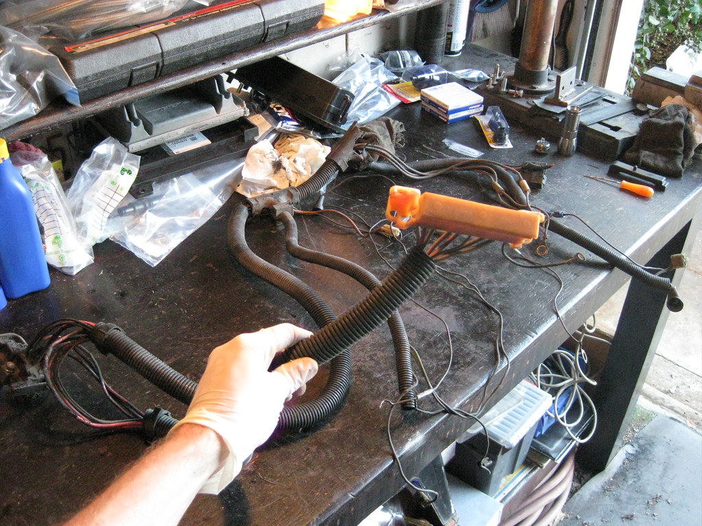
A computer would plug into these ports and perform various diagnostic functions. I called one of Dad's old mechanics that used to work on these back in the 70's and 80's and he said you could use them for different things, like starting the car from under the hood, but that it was essentially a big flop and no one used it.=center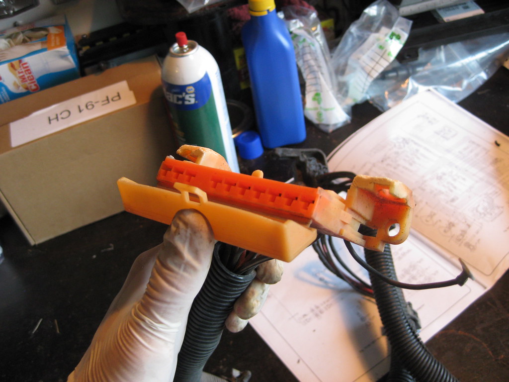
Many of the wires were spliced together from the factory inside the harness. I used a multi-meter and wiring diagrams to determine which wires went to what pins in the firewall bulkhead connector. =center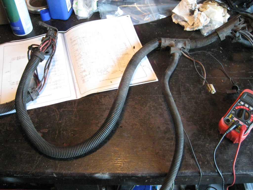
I stripped out as many wires as I could and eliminated the diagnostic port and then labeled the remaining wires.
=center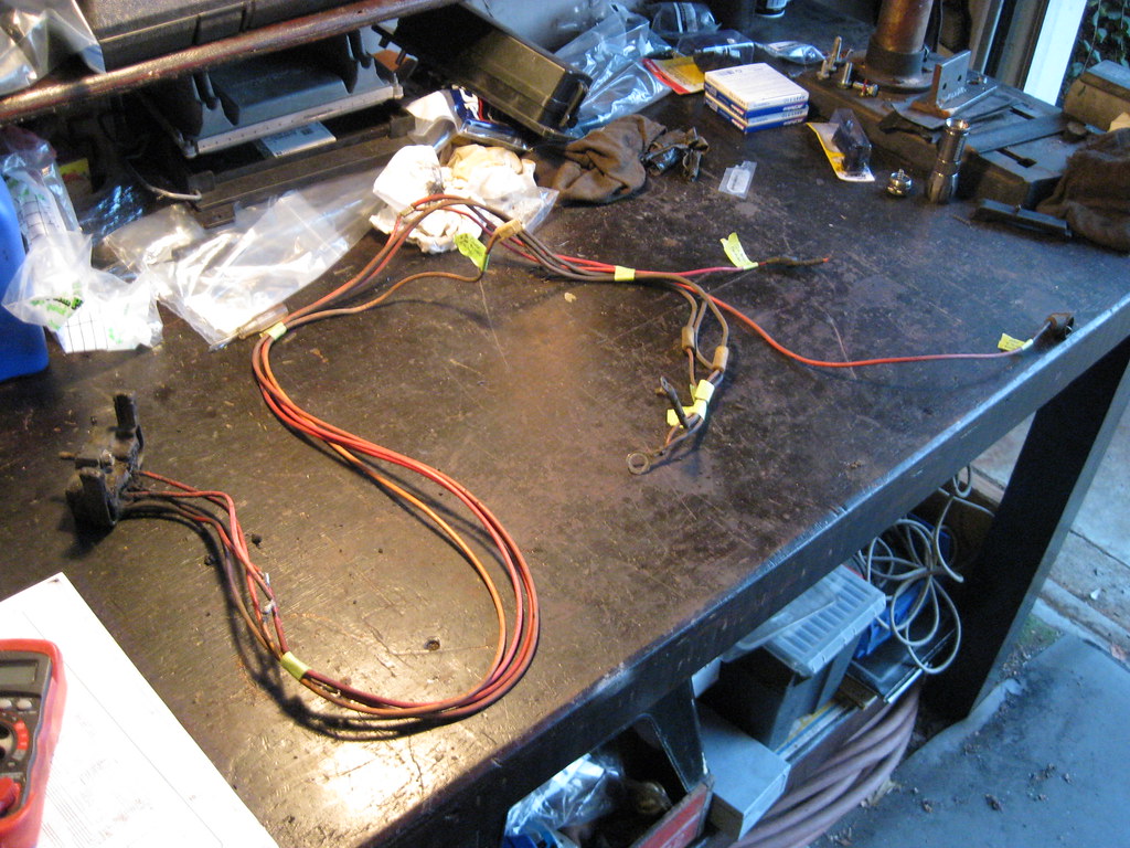
I ended up with only 4 connectors on the firewall connector.
=center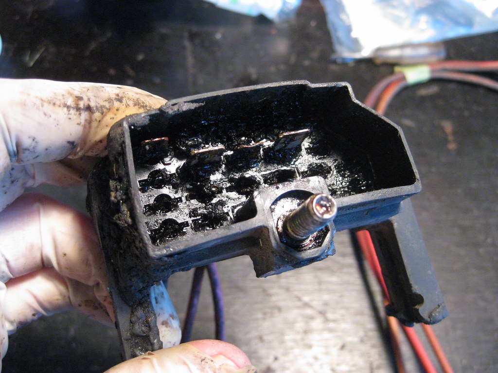
I had to remove some of the factory tape that GM had used to cover and seal these factory splices. It was a thick type of material covered with a gum substance. I de-pinned each wire, wrapped the exposed area with black tape and then covered it with head shrink tubing with sealant to be water tight.=center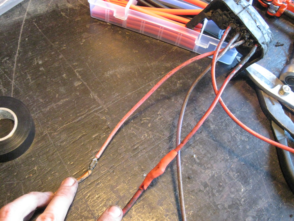
I then covered the wires with black tape.
=center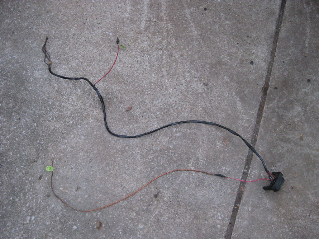
And reinstalled some of the original loom. The red wire that splits from the top will be for the high setting for the HVAC blower motor, which takes a full 12 volts. These connectors were bad about melting the harness connector, and this car is also afflicted with that issue, so I'll be adding a new weather tight connector and probably adding a weatherpack connector for the remaining wires on the connector like I'm using on the underhood fusebox. The single wire on the bottom is the old wire that powered the HEI. I will now be using it to power the relay that will power the side of the fusebox that will be ignition positive.=center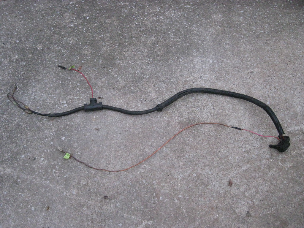
There are many different correct ways to combine the original wiring and the new wiring to power the starter, fusebox and alternator. Below is a diagram of how I chose to wire these accessories.
=center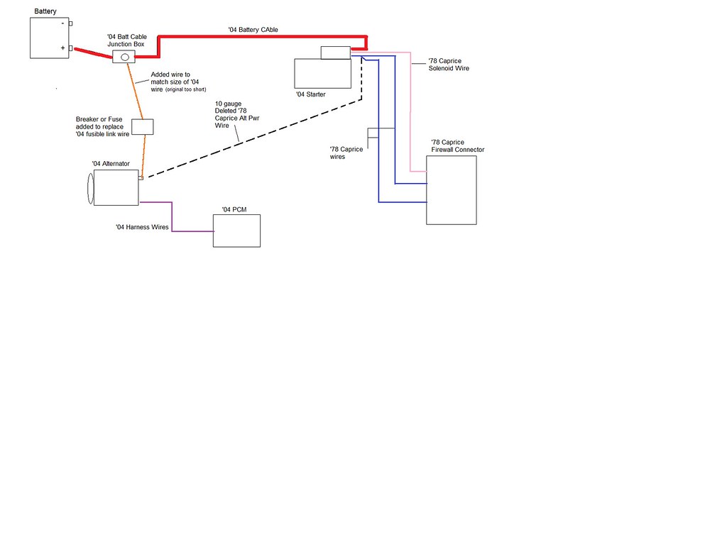
10-07-2018, 10:22 PM
#69
I laid out the harness inside the engine bay to get an idea of where I could mount the PCM and where the wiring would need to be spliced for the fusebox.=center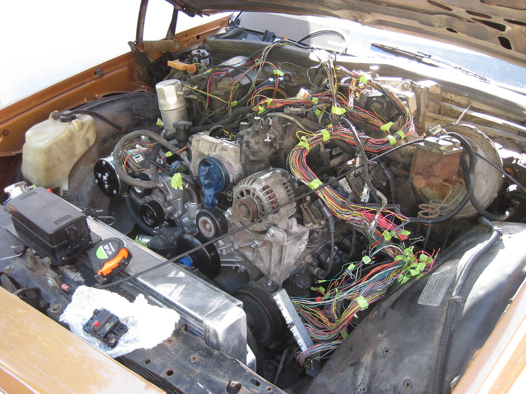
After a lot of consideration and deliberation I ended up with a mounting solution. I was finally able to find some 1/8 steel by going to Nashville to a steel provider. I first mounted the PCM.
=center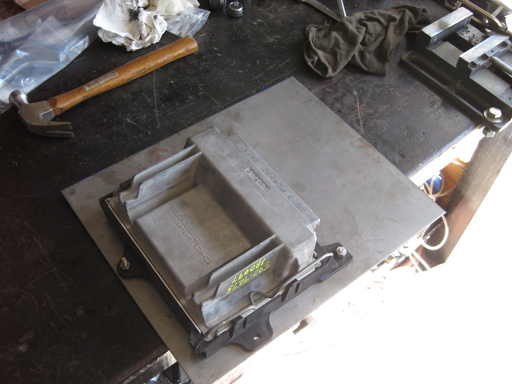
Then I began measuring to mount the fusebox.
=center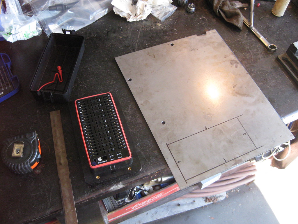
Getting a perfectly tight fit with an angle grinder took a while.
=center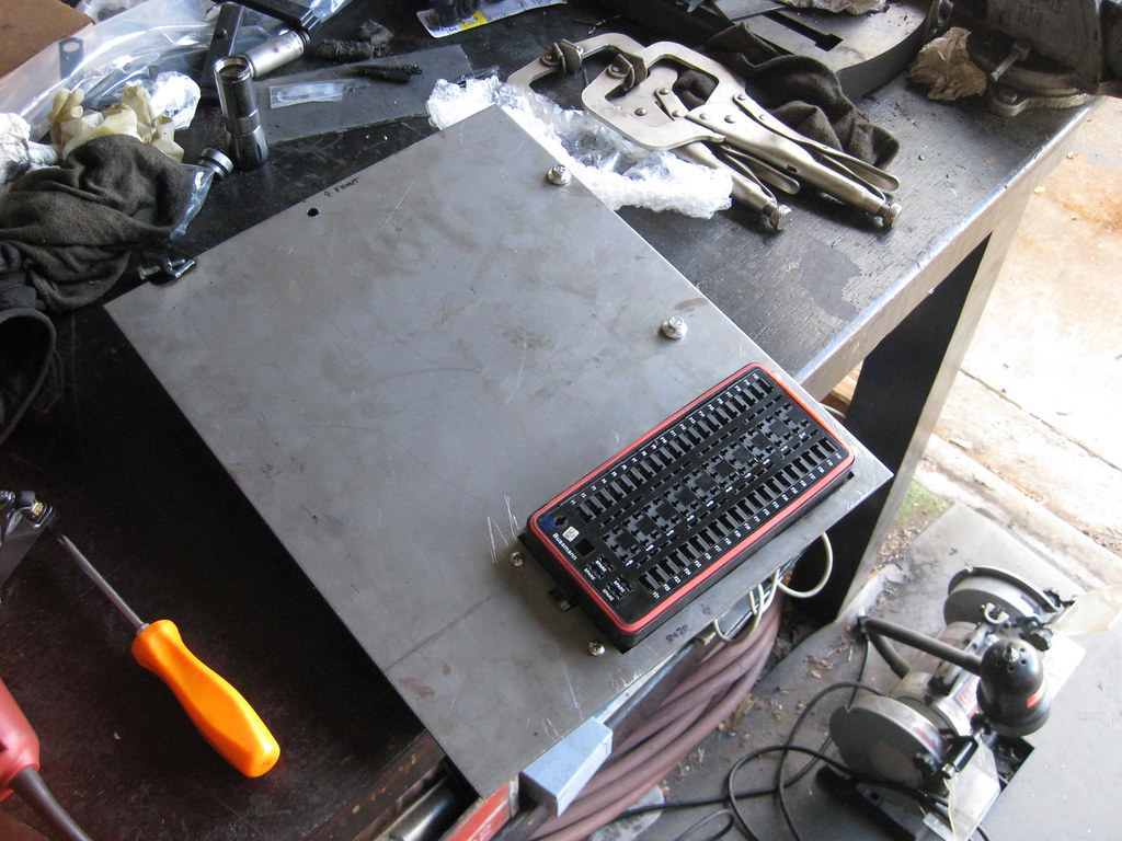
The underside.
=center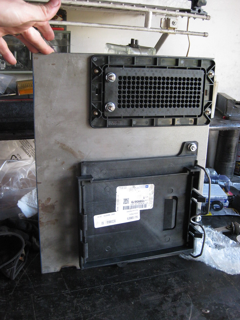
Getting everything laid out and fitting correct took a lot of testing, measuring and drilling. I mounted the breaker on the topside so that I can see the reset button.=center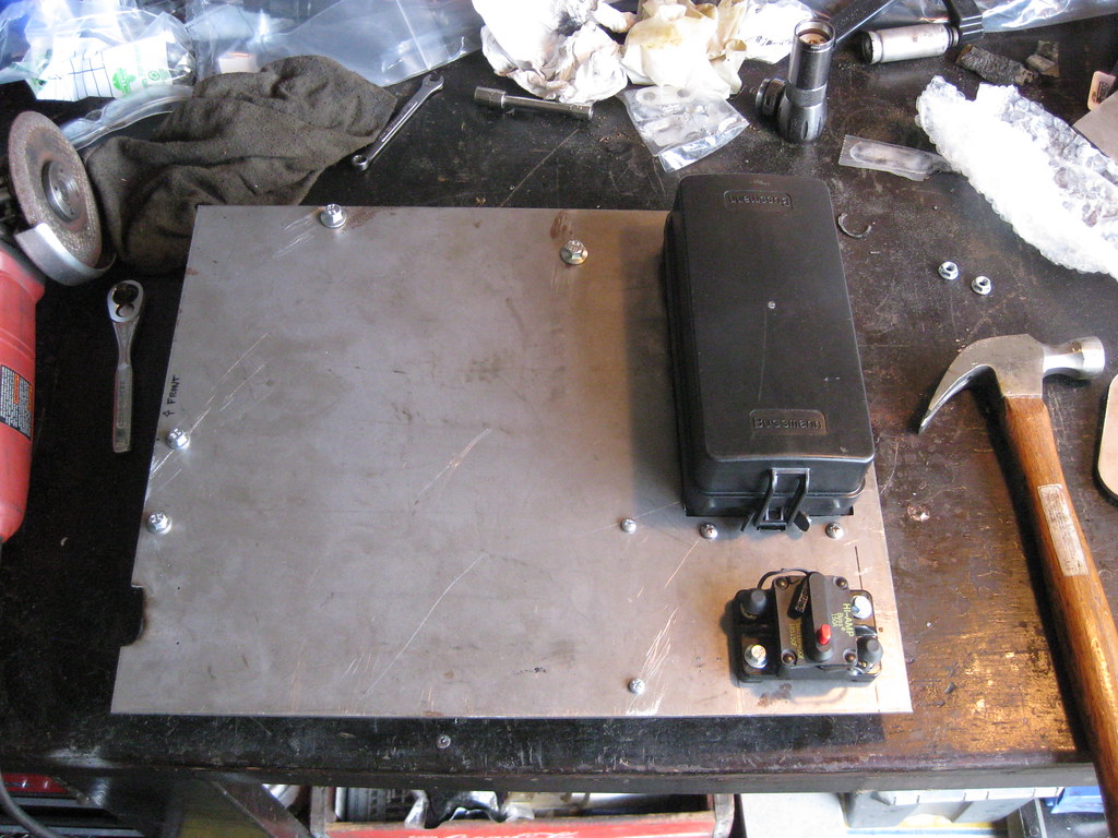
I mounted the distribution block I'll use for the ground on the underside.
=center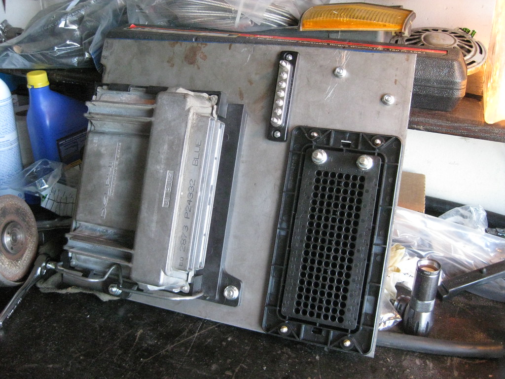
The plate will mount like this.
=center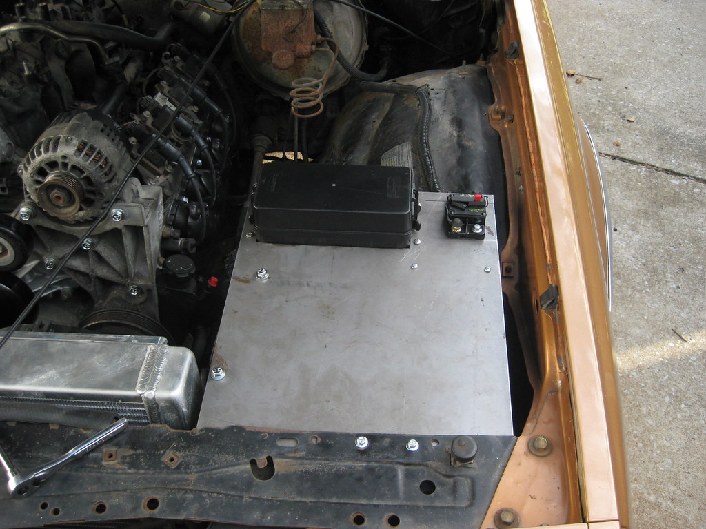
My hope is that the air filter will fit under the PCM and this area can act as an airbox as well as protect the wiring from the elements.=center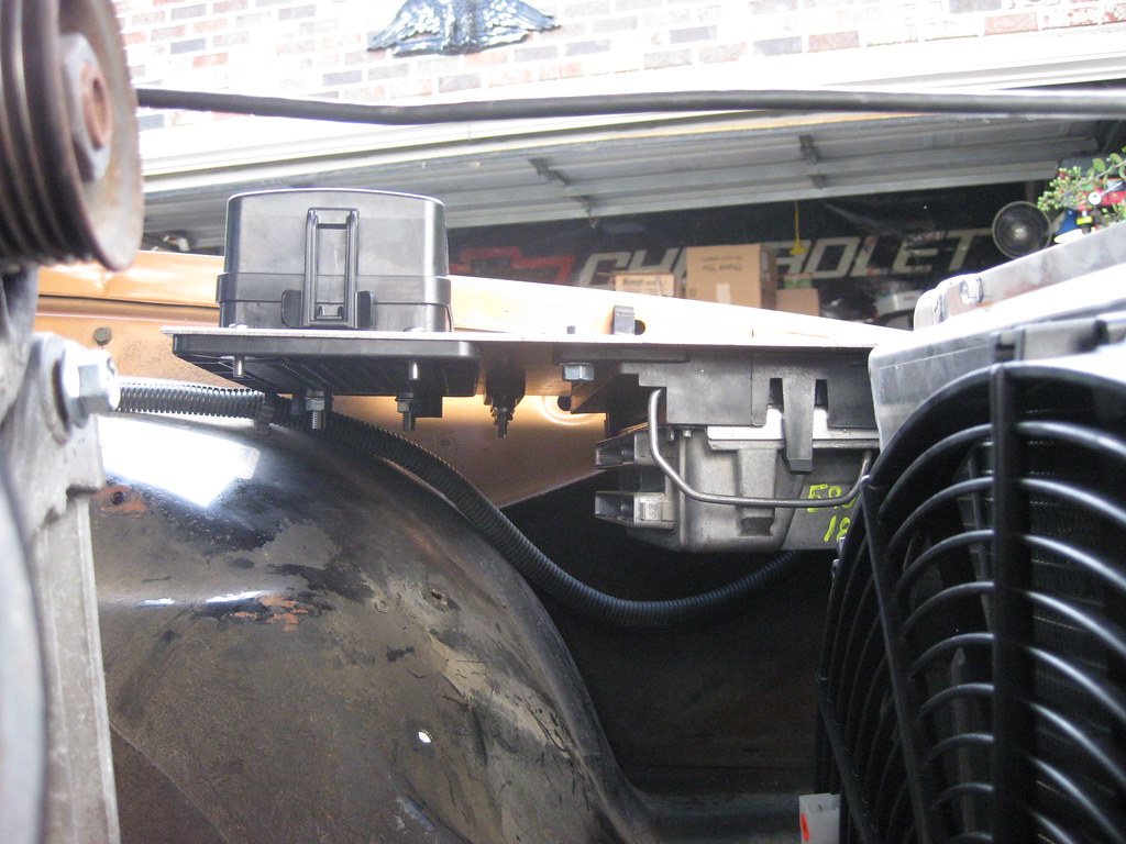
=center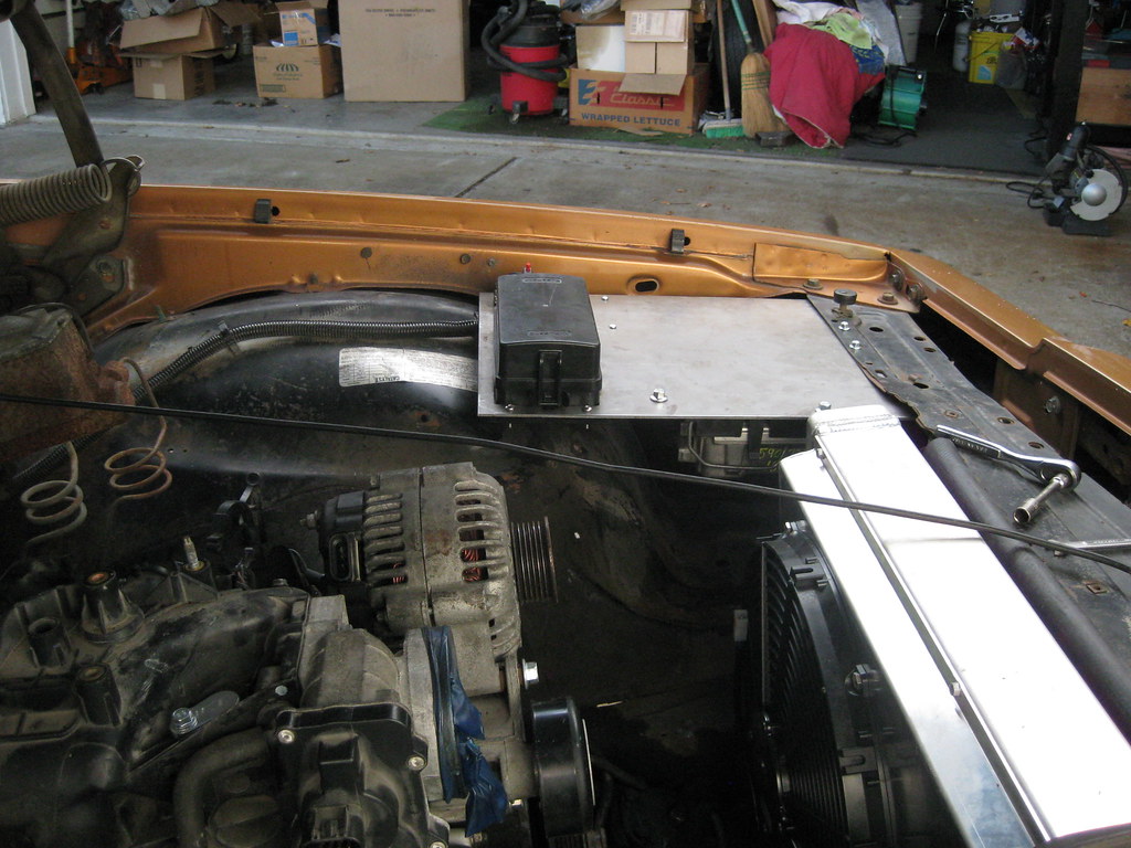
I also needed to add a mounting support for the rear.
=center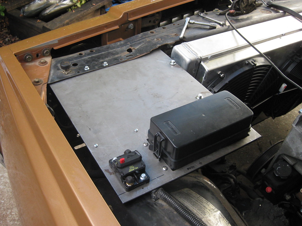
So I used this existing hole that was already in the fenderwell.
=center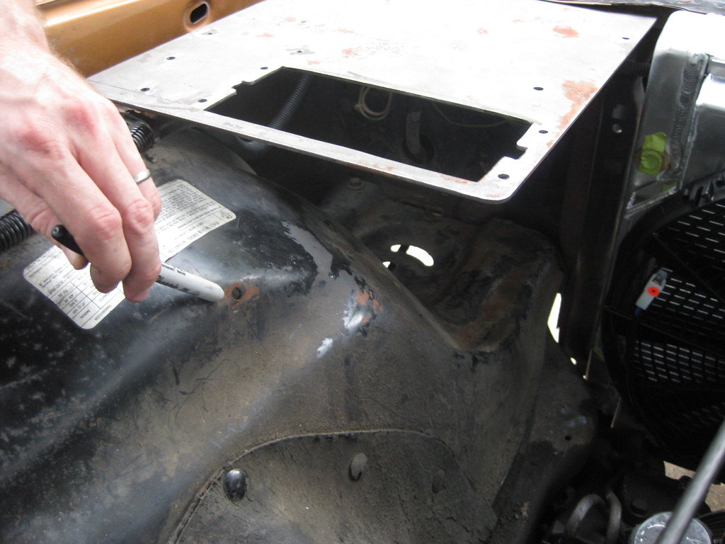
I had these items in my scrap pile, so they will become the rear support.
=center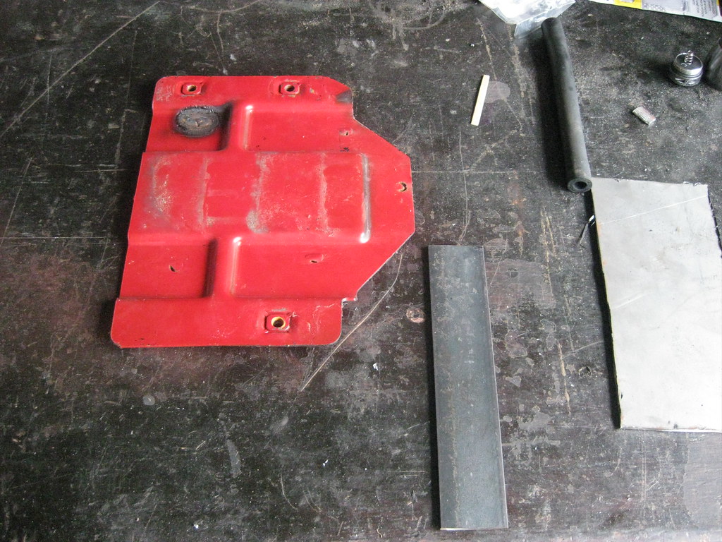
The bend on the mount was difficult because of the complex angles involved. They included bends with twists in order to correctly line everything up.=center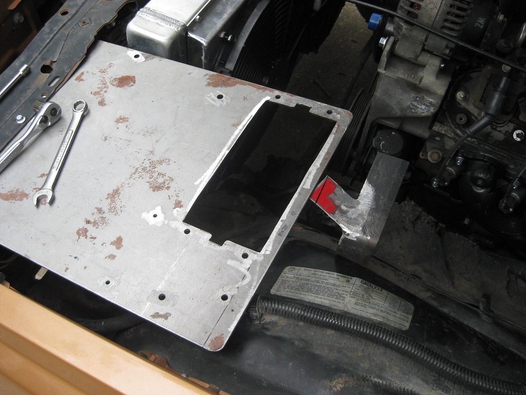
Below is a picture after welding it all together. The fusebox on the original Avalanche sat in this area and the wiring harness originated from this point and went straight to the engine over the front of the driver side valve cover. Because at this time I am not able to modify every wire in the harness this location will work well because the harness will fit back near its original location in relation to the engine. I will use the extended piece on the rear mount I made below to have a clip to hold the wiring harness in place.=center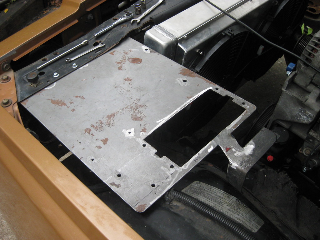
I rounded off the edges of the harness mount.
=center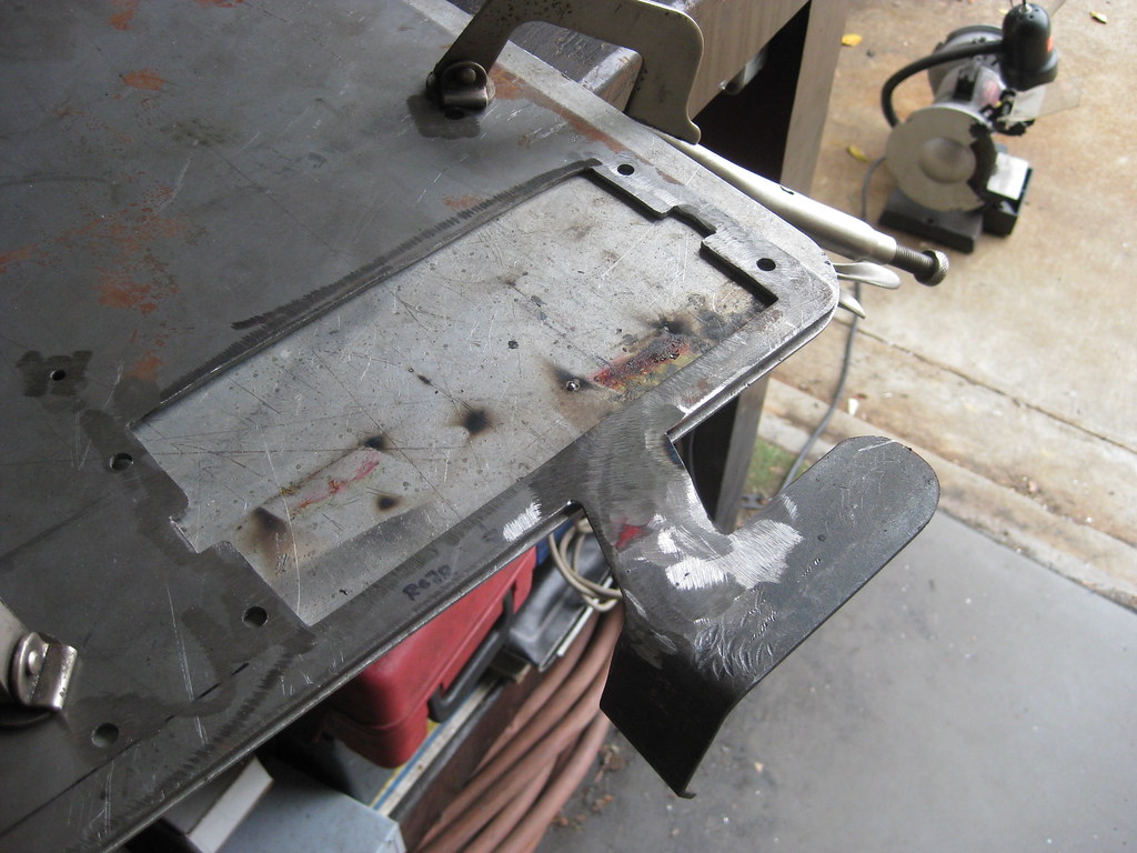
=center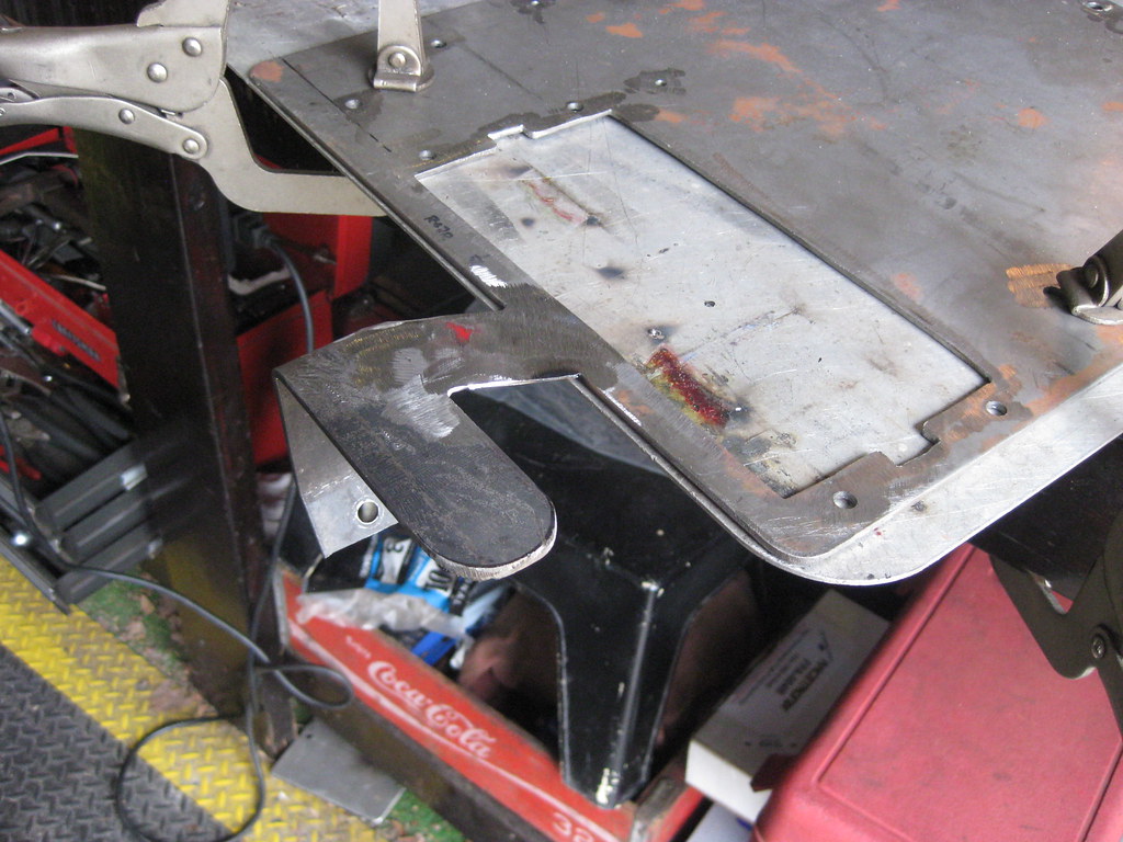
And then I made a panel to hold all of my large relays that are too large for the micro relays used on the fusebox.
=center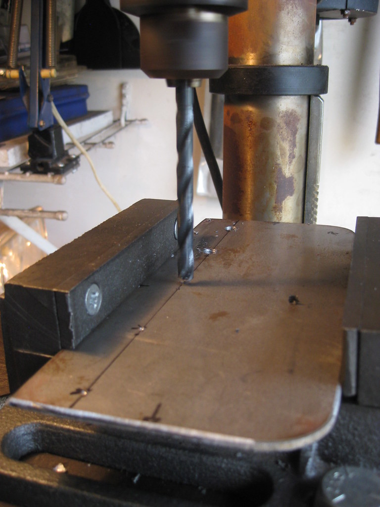
I used a steel brush and put a coat of primer on the mount so it would be easier to handle while I'm working on it inside at the dining room table. I'm not sure what was going on with my welder on the relay-panel but I could not get a steady bead. It was more than strong enough but looked terrible. The irony is that the other welds turned out OK, but they are the ones that had to be ground off. This simple panel took almost two full days of work to complete. Getting the holes drilled in exactly the right spot took a lot of time.=center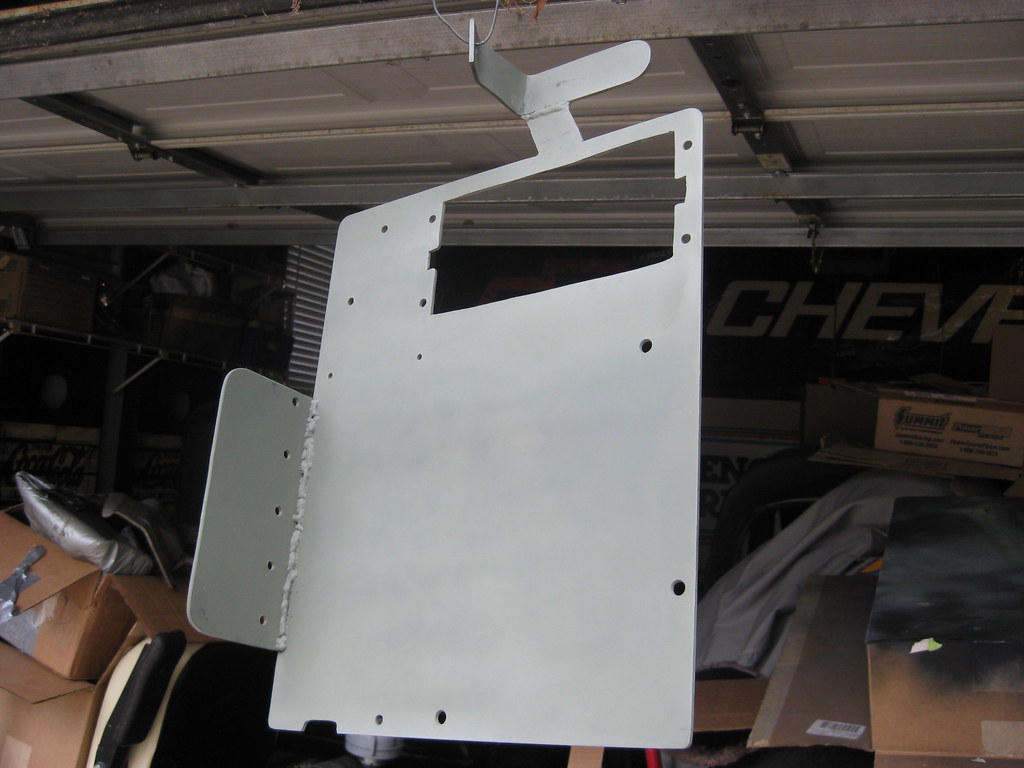
10-07-2018, 10:23 PM
#70
I turned the dining room into a makeshift laboratory. I have about four binders of emails, charts, diagrams and instructions on how to get everything wired together. Fortunately, a lifesaver of a person compiled a great article on how to wire a fusebox similar to the one I have and put it on the internet. The one he used was different than the one I'm using but it was close enough that I was able to make it work. Just learning about all the different connectors and sizes and parts involved and then making sure to order the correct pieces to make everything fit together was hours of investigation. I spent more than one night up past midnight researching and compiling the correct parts to order for the fusebox. If I had directed this much effort into academia I would have a masters degree by now. I ended up calling the company that makes the fusebox to distinguish the differences in their products so that I made sure I ordered the right one. I ended up ordering a dual buss fusebox, which means each of the two columns of fuses has its own power source and ten micro relays are in the middle. I'll power one buss with a direct 12v from the battery and the other will only receive power when the key is on. We took a vacation for a week during this time and I printed out several internet threads and emails I've been exchanging. Each night when everyone else would go to bed I would sit up and read over all of the information, reading and re-reading until I could finally begin to wrap my mind around the process. Besides understanding how everything is supposed to work, understanding what parts to order was a huge task. =center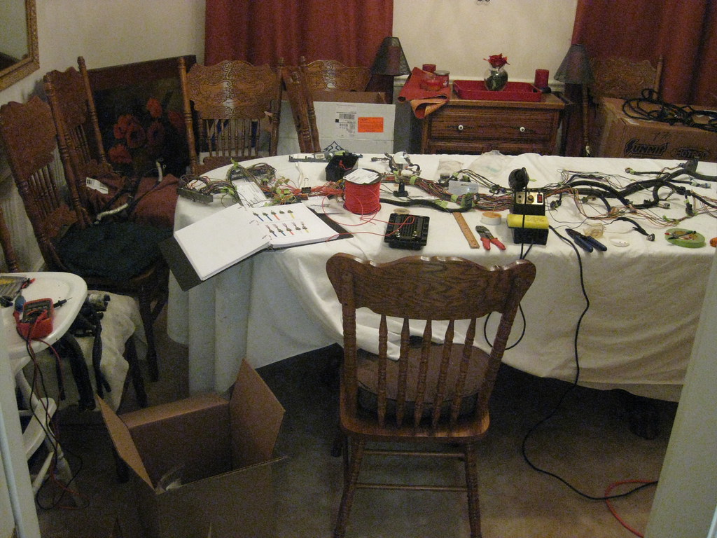
To build the fusebox first you insert the correct size seal and measure out the right distance of wire.
=center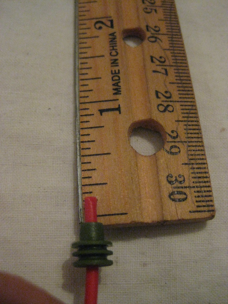
Then strip the wire.
=center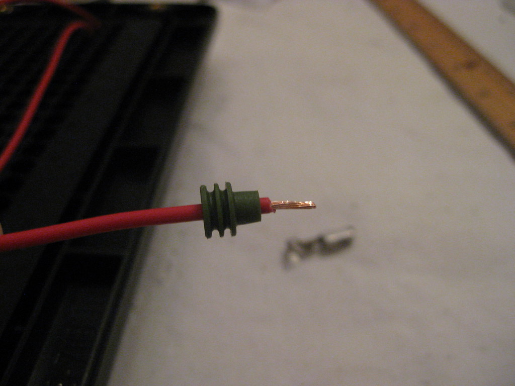
Crimp on the correct end for the connection type. I purchased this special crimping tool and it was well worth it.
=center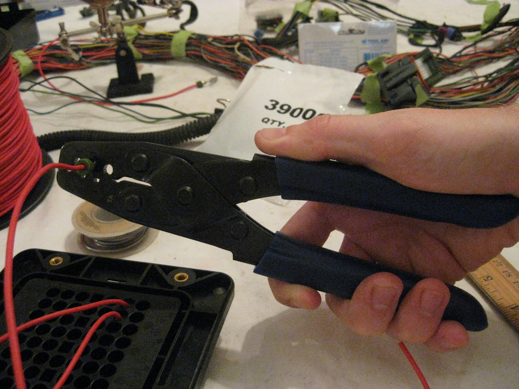
This is the crimped connector with the weather seal crimped as well. The particular fusebox I ordered uses female connectors with a tang that holds them in place once installed.=center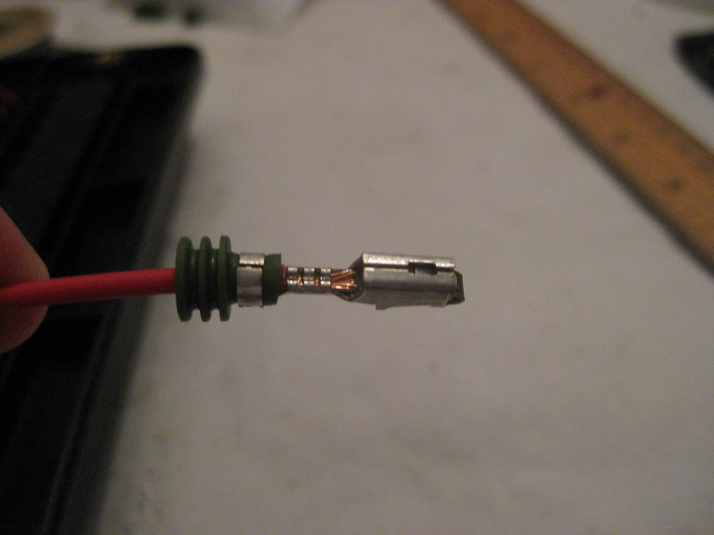
I borrowed this tool from a friend of mine and it made working with the wire much easier.
=center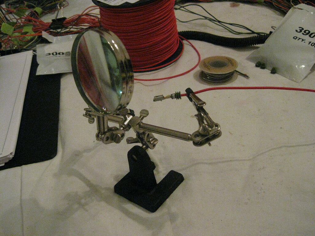
I have never been able to do a good job of soldering wires together. The solder would never create a good connection. I knew with as much soldering as I would have to do on this project I needed to learn how to solder so I did a lot of reading and watched a lot of videos on the internet. I found out that the list of things not to do seemed like a list of everything I had been doing when trying to solder. One of the biggest keys was using solder flux.=center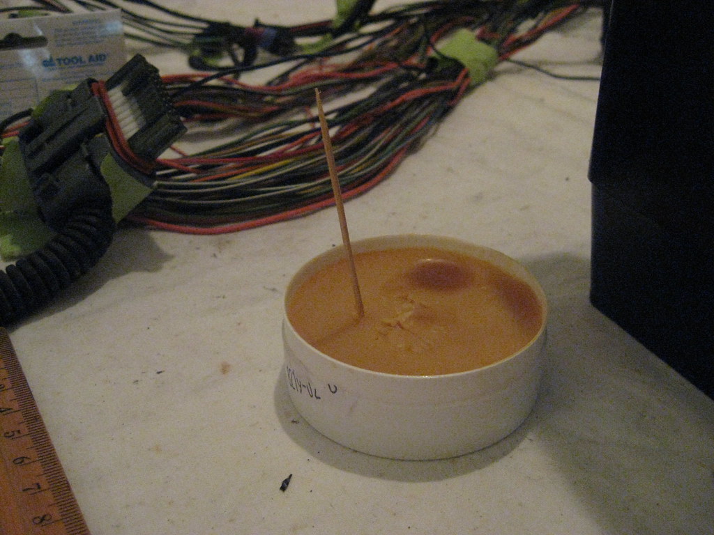
The flux is applied to the area and melted into the wires. Once melted it draws the solder down into the wires, causing it to flow in and around the desired area rather than pool above and roll off the wire. It's also good to use for cleaning off the tip of the soldering iron.
=center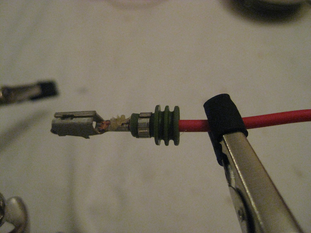
I soldered each connection.
=center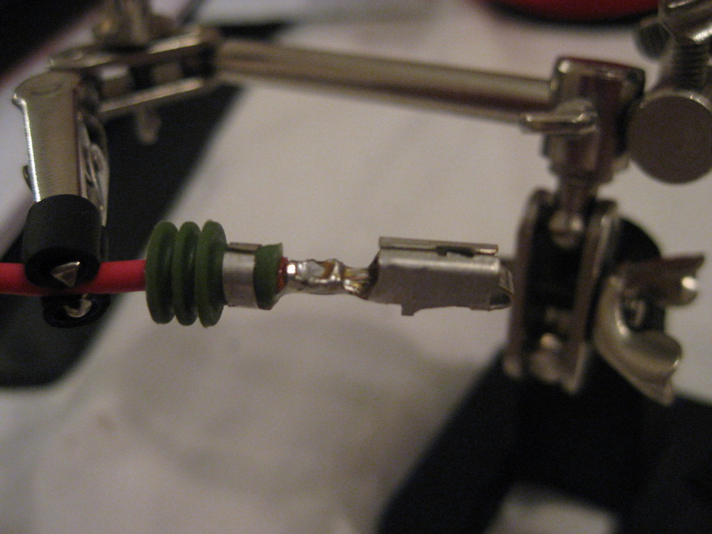
After a lot of that I ended up with this. Each weatherpack connector I ordered holds six wires, so I would create six wires at a time.=center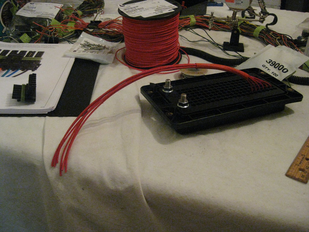
And then put the correct connectors on the other end using a similar process.
=center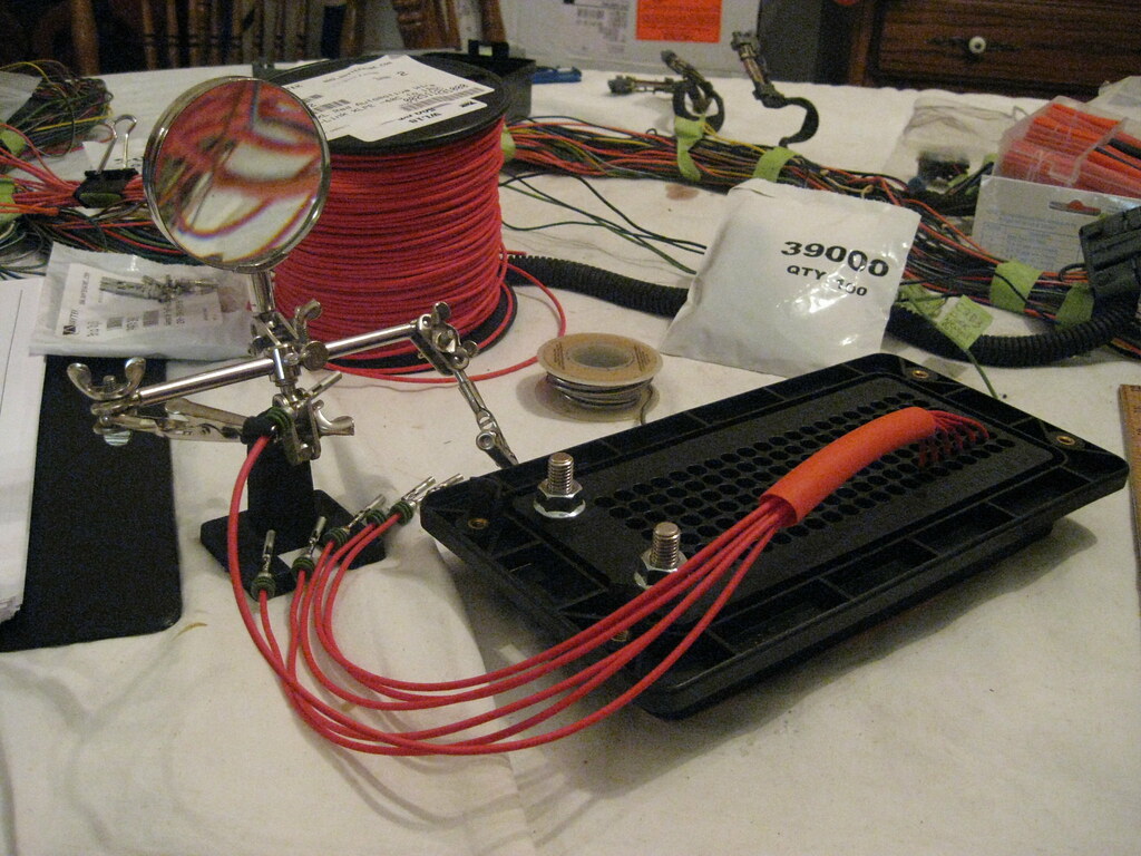
This is the finished product of the first connector. These connectors will provide 12 volts when the key is turned on. There's a lot of slow progress here. Each night I would work and get a few more wires finished up. I realized later on that I had installed every wire on this column below in the wrong hold and had to take them all out and move them. Then I realized I had not correlated the pins on the connector the the numbered fuse connector that I wanted them, so I had to unpin all of the connectors and repin them.=center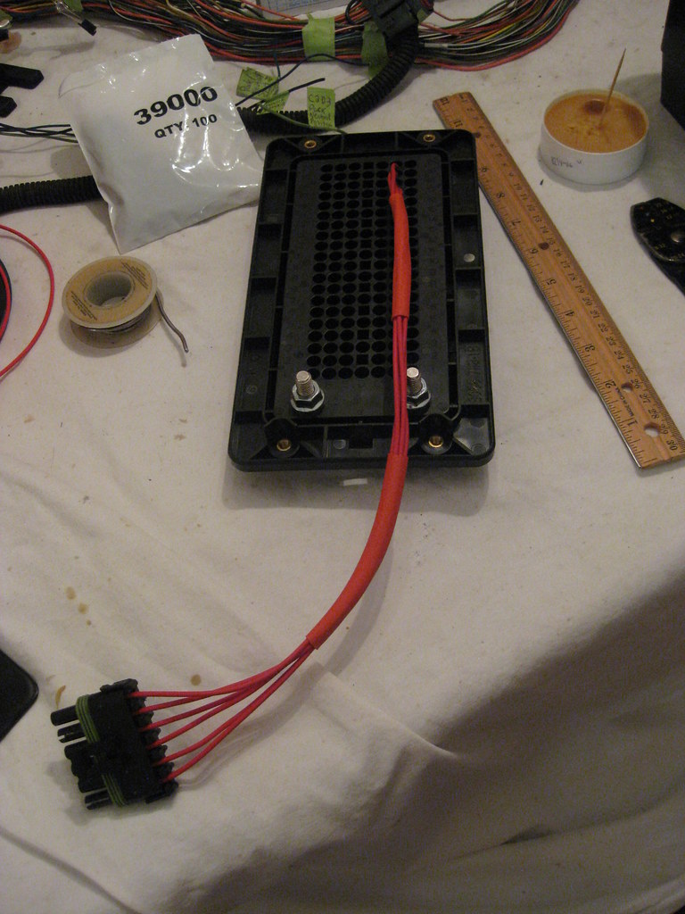
Although I didn't splice nearly as many of the wires together as many others do when building their own harness I did still have a good amount of wires that needed to be spliced together.=center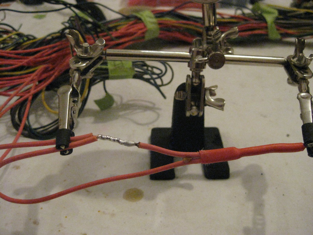
The solder flux allowed for a good, solid connection, which I followed up with black tape and heat shrink tubing with waterproof sealant.=center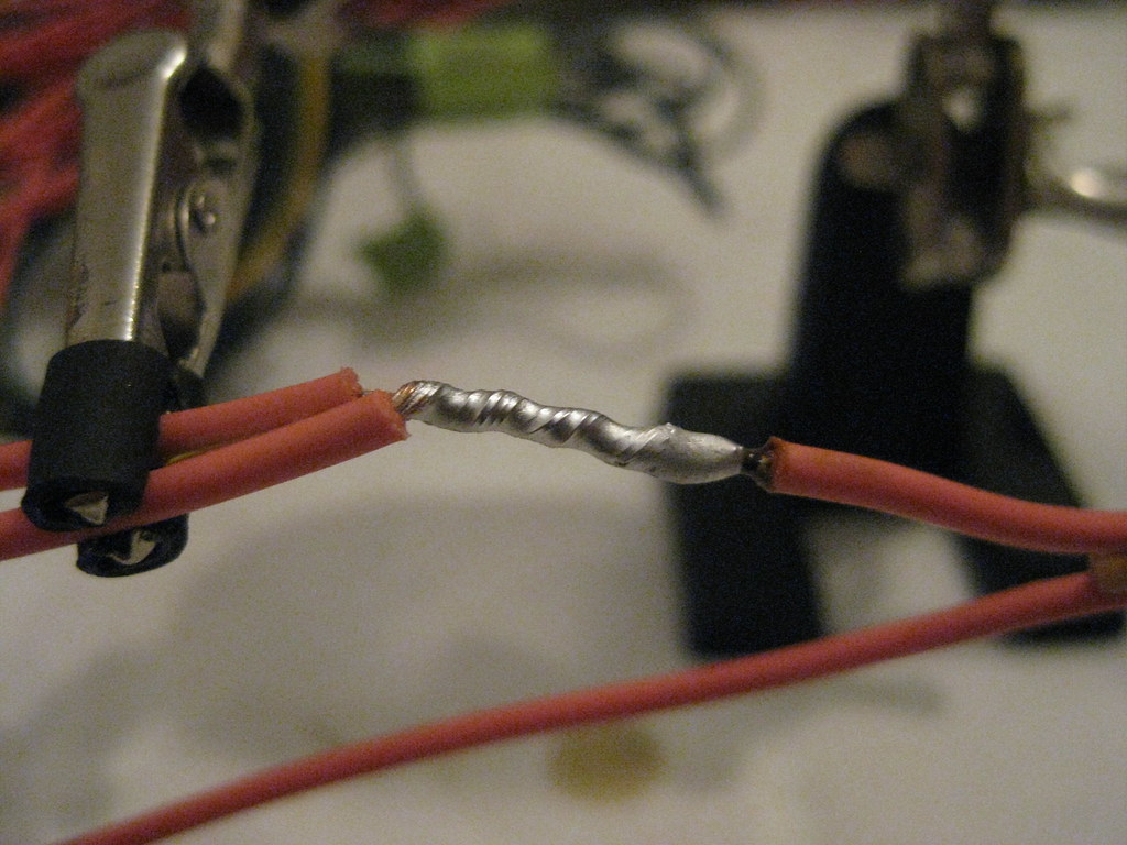
Slowly but surely I began to get all of the wires that I wanted hooked to the fusebox separated out, labeled and put in place.
=center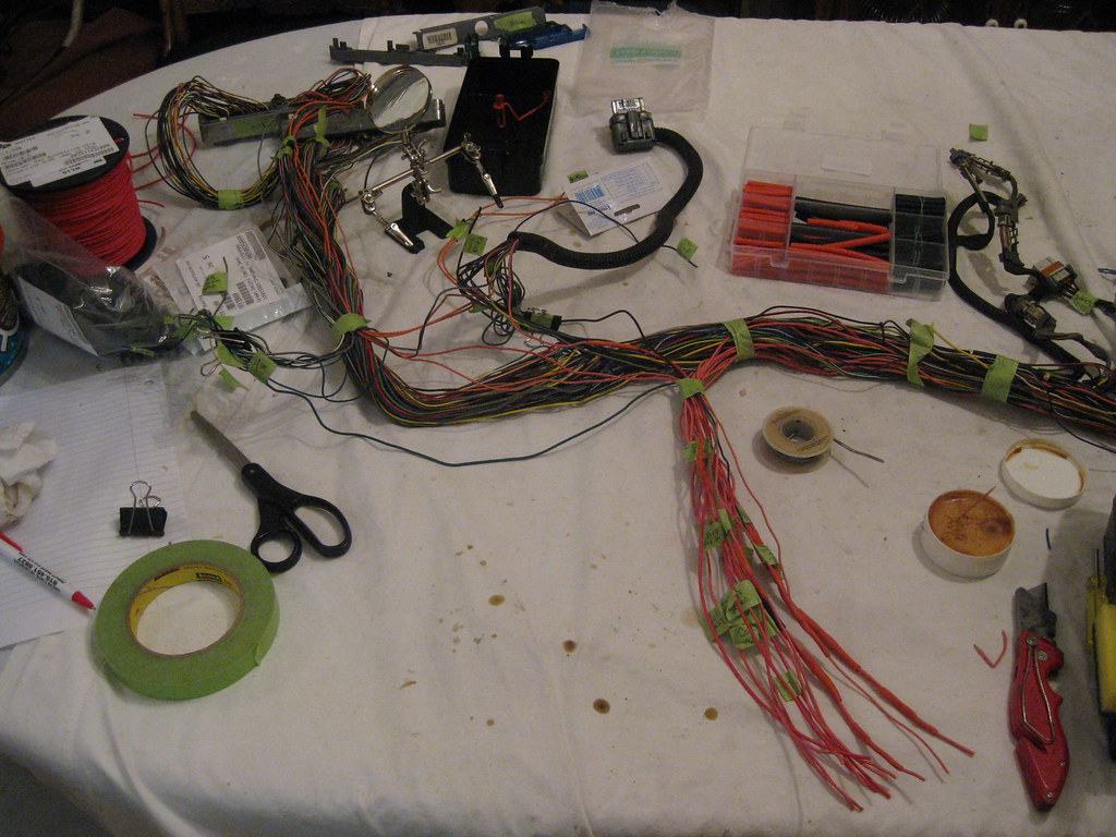
My youngest daughter always asks if I'm going to "work on my wires," and always wants to help. I don't let her hang around when I'm soldering with the lead solder, but she helps assemble the pieces together. All of these steps took a tremendous amount of time.=center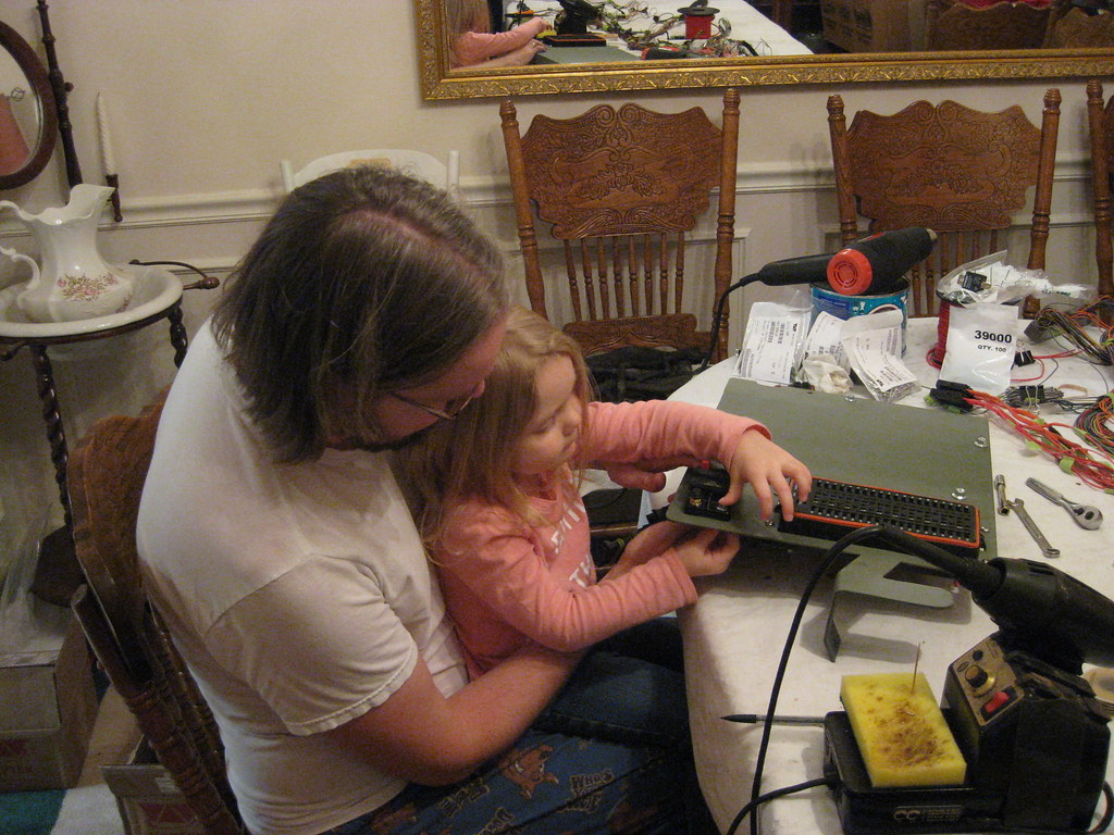
10-07-2018, 10:23 PM
#71
I used a string to measure for the new serpentine belt. I still ended up having to return two belts until the third one was close enough.=center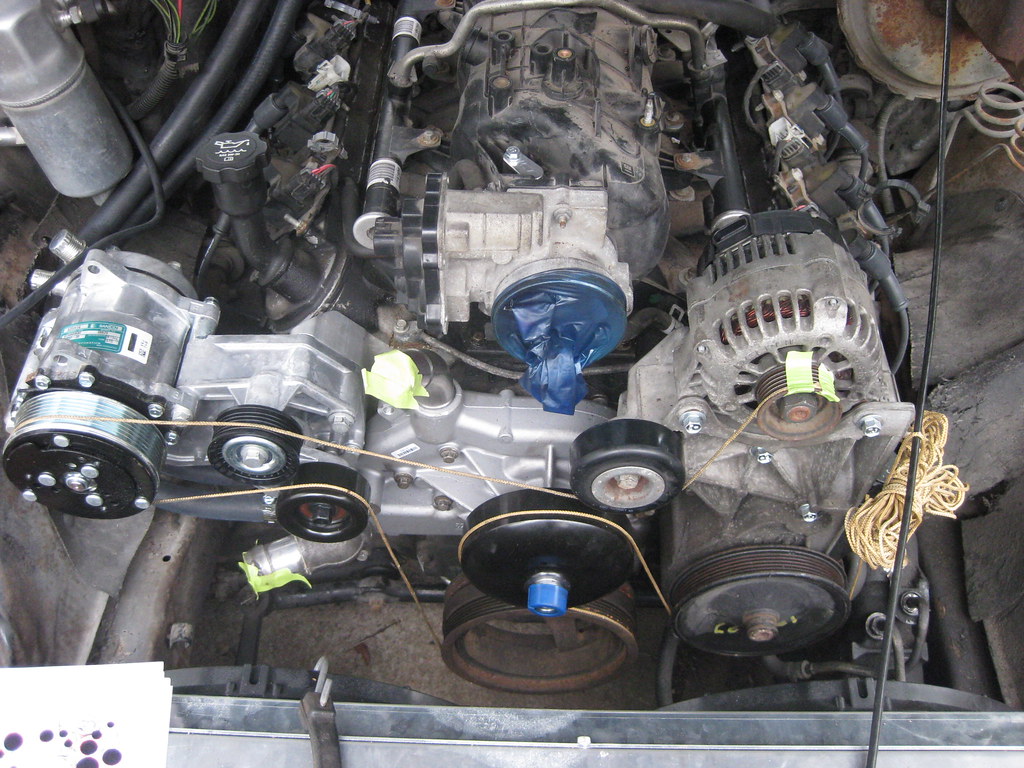
The hose coming out of the bottom of the throttle body goes to the steam vent port on the radiator.
=center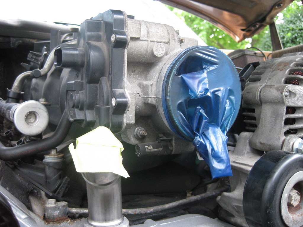
This piece mounts on the back of the driver side fuel rail and is there in case of an accident to prevent the fuel rail from hitting the firewall and puncturing.=center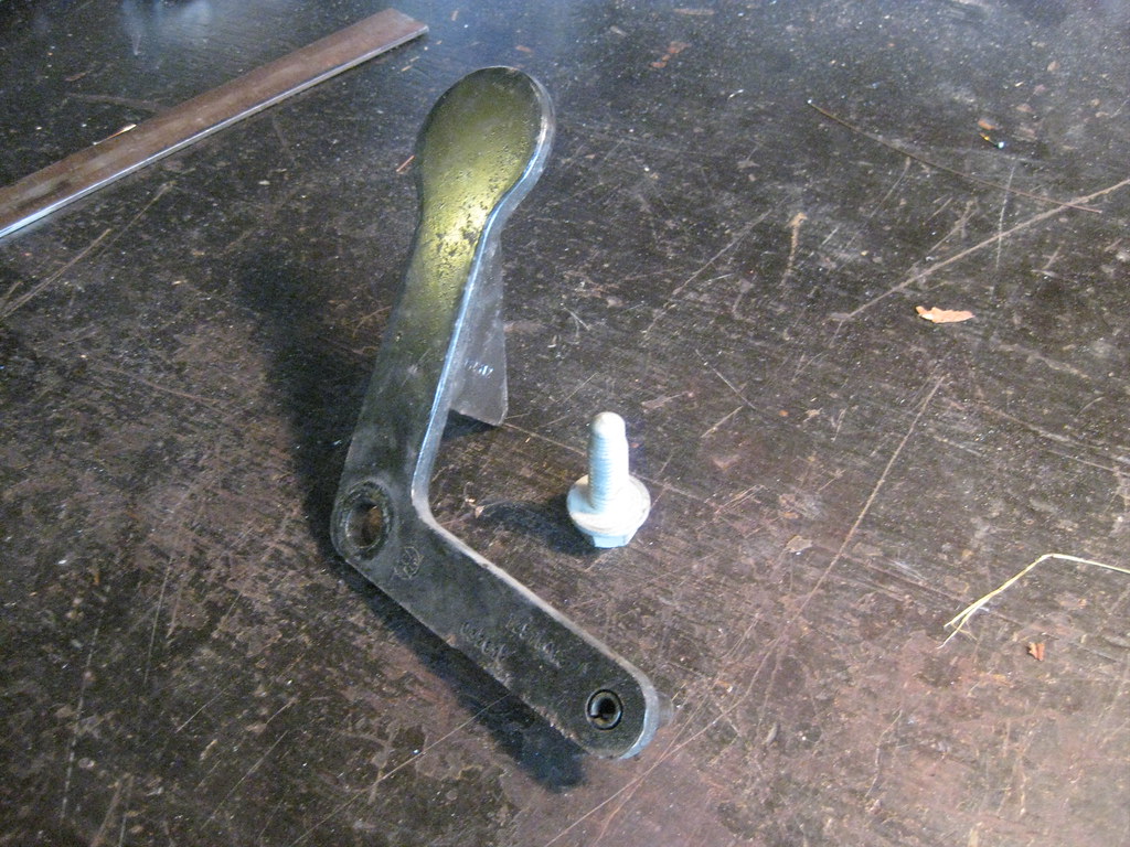
I reinstalled it in its original location.
=center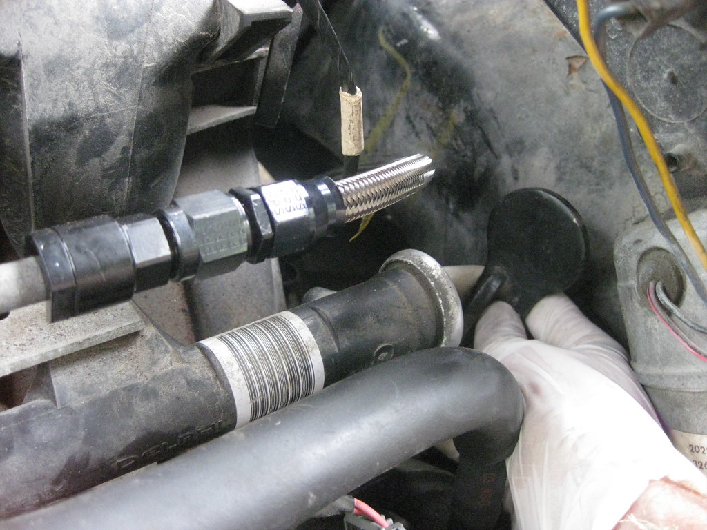
I found that the vacuum port for the brake booster was plugged on the engine. This engine originally used a hydraboost system to power the brakes, which used fluid from the power steering reservoir, so the vacuum port on the manifold was plugged. I ordered a new fitting from the GM dealership but I couldn't figure out how to remove the old plug. After reading online I found that you have to depress the red portion of the plug while pulling out on the plug itself.=center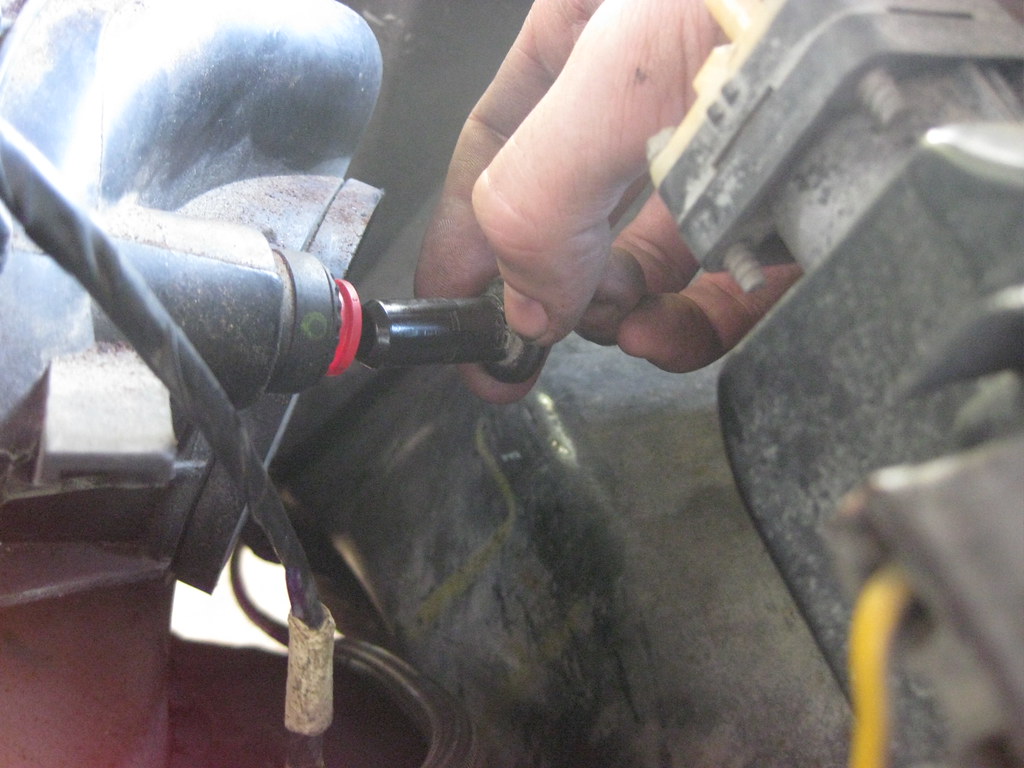
I replaced the booster hose fittings.
=center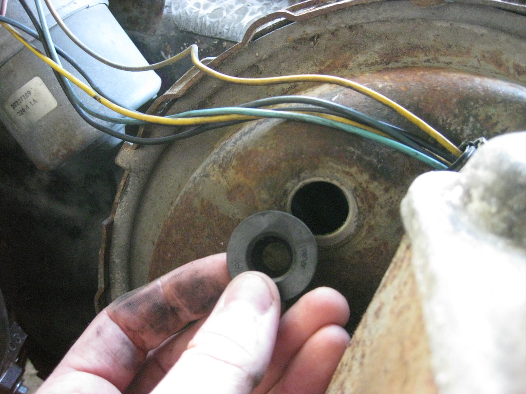
Installing the hose on the new fitting was a very tight fit. Some grease helped it go on.
=center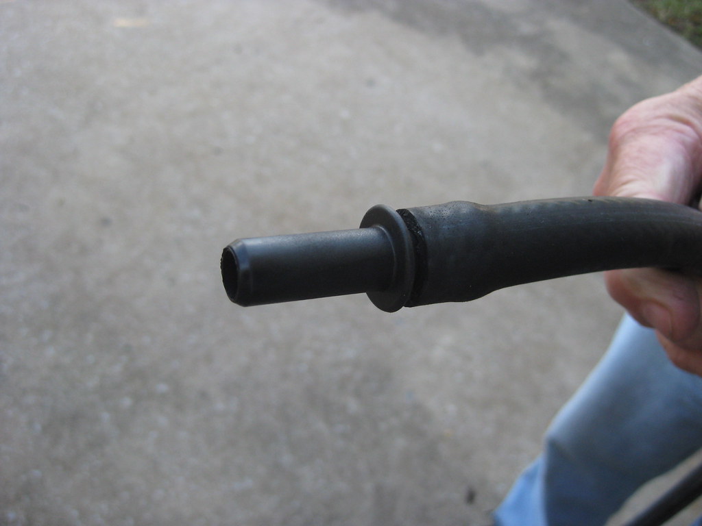
I installed a new hose filter, valve and hose.
=center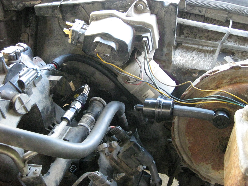
I ordered some carpet samples online.
=center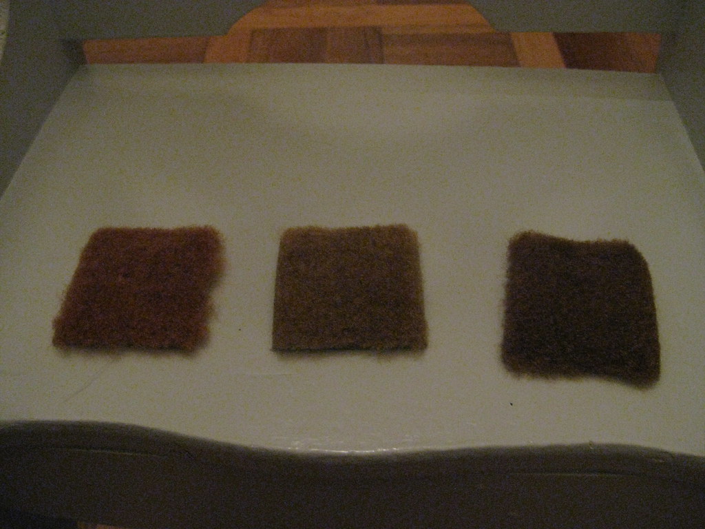
And after a couple weeks the girls had a new playmat.
=center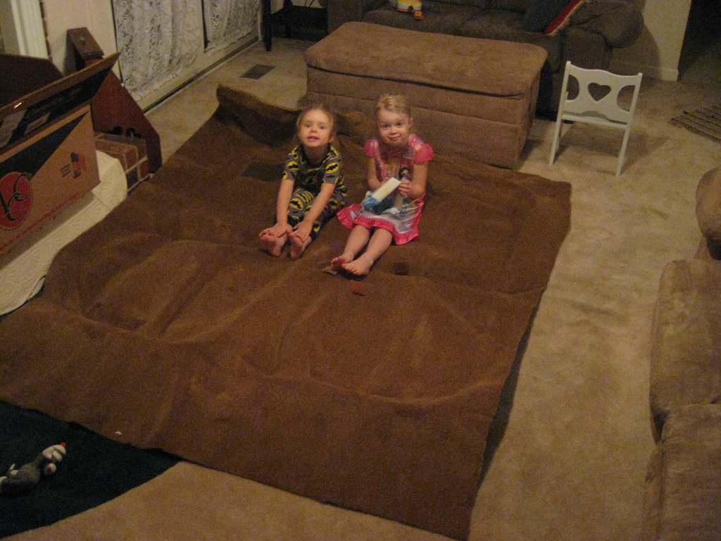
I could not believe how difficult getting the upper radiator mount was. Finding the steel was difficult to begin with and then I couldn't find anyone who could bend 1/8" steel. I looked into buying my own metal brake and reinforcing it with metal gussets, but even that was going to be a gamble. After several dead ends, finally one machine shop sent me to another machine shop that sent me to another machine shop that gave me the information for a final machine shop that was able to make the bends. I noticed that the angle on the rise didn't appear to be steep enough. After getting the metal closer to the appropriate size I tried to make it work but realized it wasn't going to fit correctly. I'm going to try to take the piece back to the shop and see if they will increase the angle of the bend.=center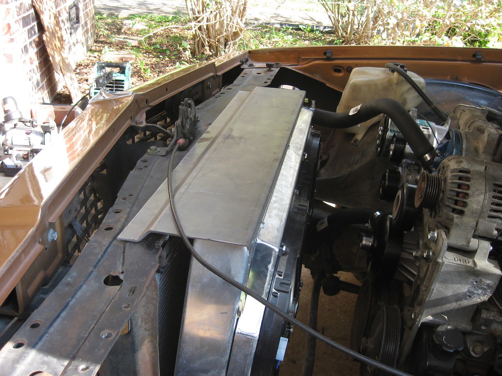
After a lot of searching I found some radiator hoses that will fit. If I could find a thermostat housing that would point down at the 6 o'clock position at 90 degrees and would maintain use of the original thermostat I would have no trouble but after a lot of searching I haven't found a thermostat housing that fits what I'm looking for. In the future I may try to come up with something better, but for now what I have fits fine.=center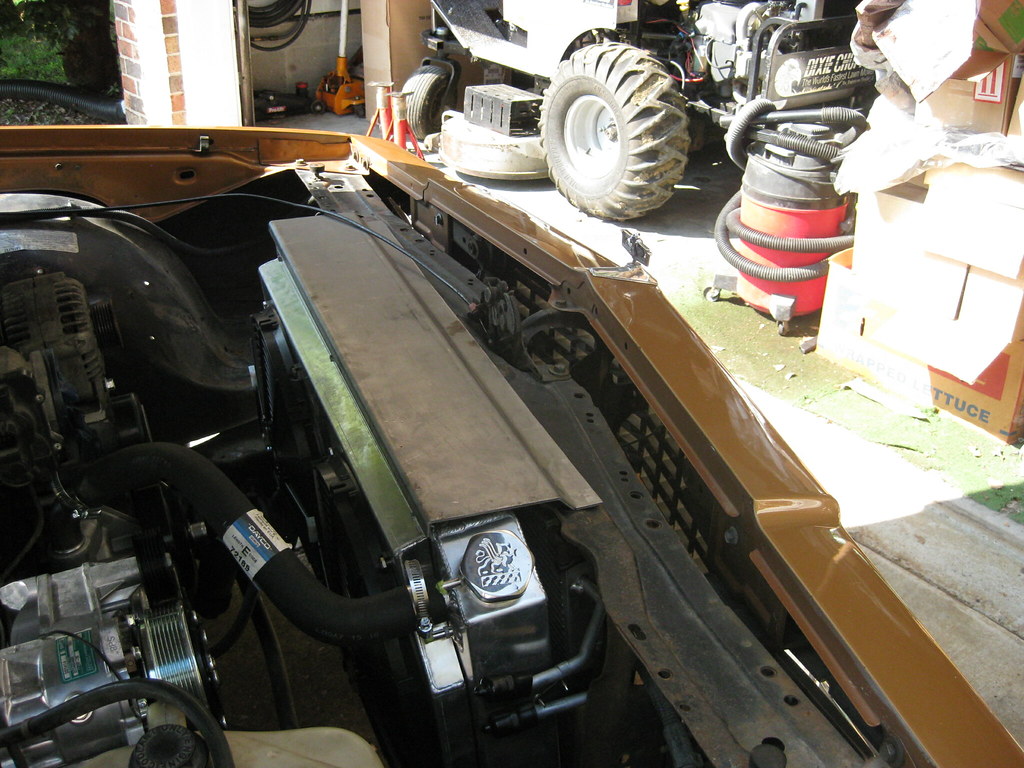
I had ordered the fittings for the new transmission lines quite a while ago. It was a long process to figure out exactly what types of fittings and adapters to make everything fit together. The radiator uses NPT thread and the transmission uses NPS, or visa versa, and the hard line uses an inverted flare fitting. At first I was going to use steel braided line but then I realized that the radiator fittings were on the driver side and the transmission fittings were on the passenger side so I decided to go with hard line. I went to the parts house and rented a flaring tool. Even with soft copper nickel lines this garbage tool wouldn't work. First, it didn't leave enough room for the line and adapter to fit inside the tool and then it couldn't bend the flares correctly and the threads on the cheap tool ended up ruining. I've used these rental tools many times, so I knew I was using it correctly. I went to every parts house in town and they either had the exact same kit or had no kit. After wasting too much time driving all over creation I gave up on rental tools. I have grown tired of poor quality rental tools in the past and have decided to order a good quality flaring tool. I am currently waiting for it to show up at which point I will be able to install the hard lines. After these lines are installed I can then have the exhaust installed.=center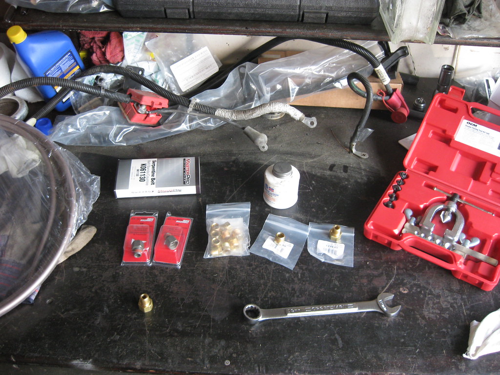
Bad flares.
=center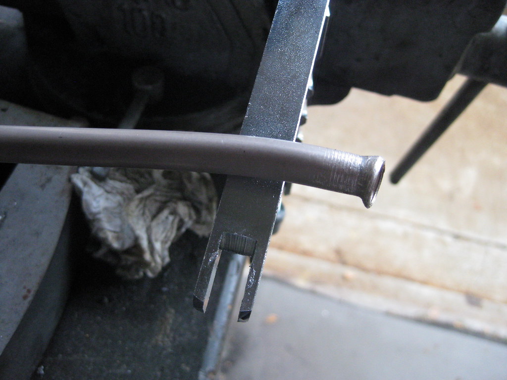
After I was unable to work further on the upper radiator mount or the transmission lines I moved on to some other items that needed to be finished. I installed the neutral safety switch.=center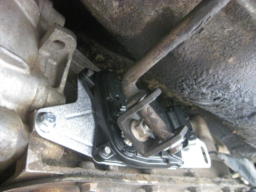
I tightened down the fuel pump as well as the fuel pump line fittings.
=center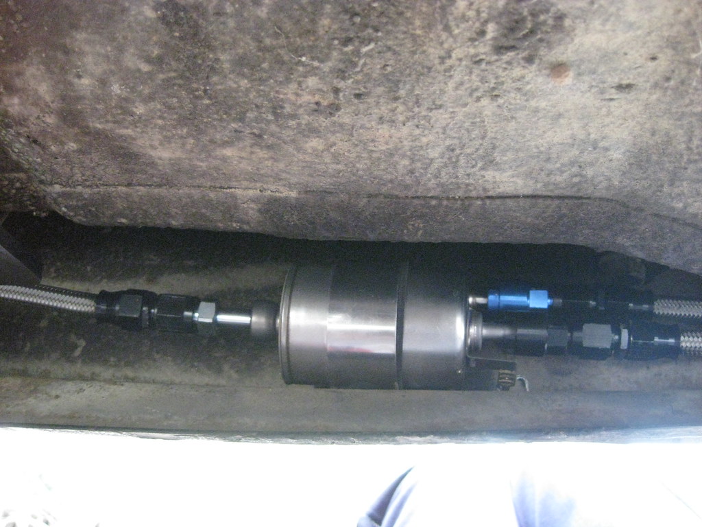
Added some final fuel line clamps.
=center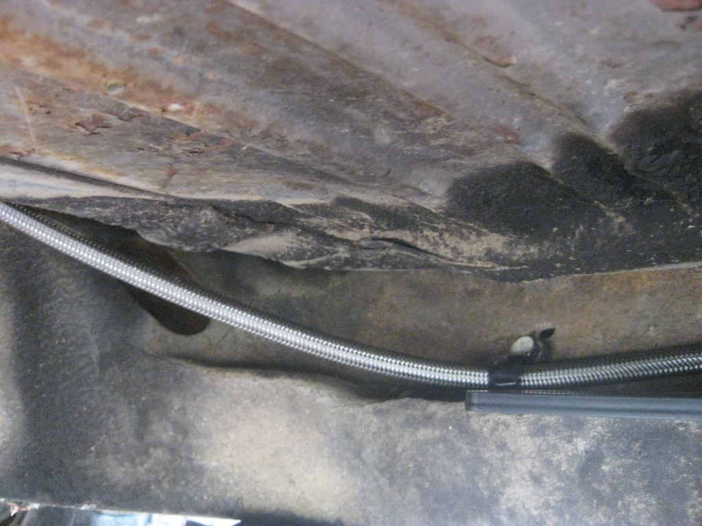
Finally installed this bracket for fuel lines I had welded onto the old exhaust hanger.
=center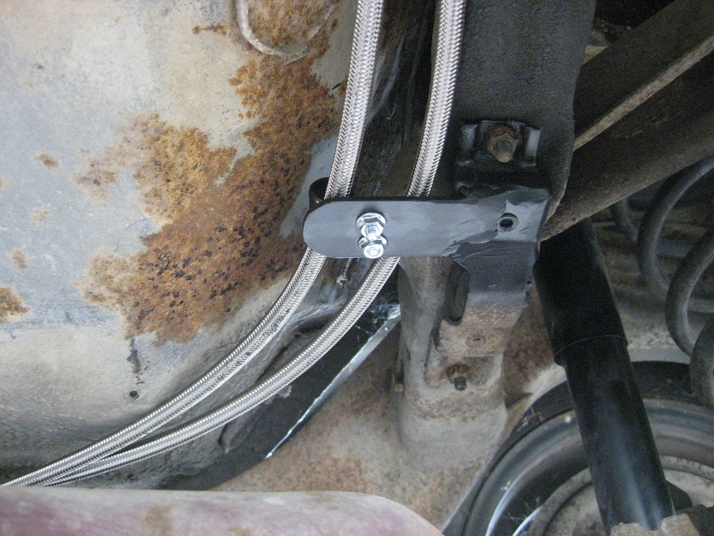
My solution to hold the fuel lines over the rear axle was to modify a standard hose clamp. The small screw on the bottom was the original and the clamp was only intended to hold two hoses apart but did not mount to anything. I got a longer screw and added a washer so I could mount the hoses on the frame, between the frame and body over the rear axle.=center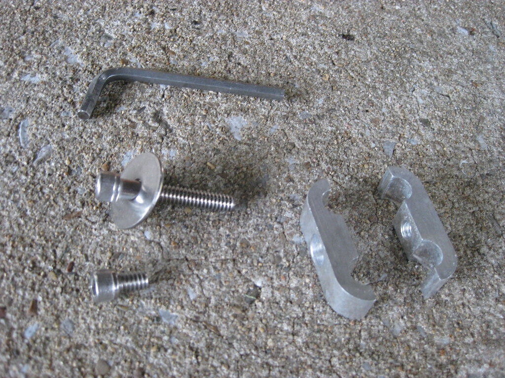
The clamps keep the hoses in place and keep them from rubbing on the frame.
=center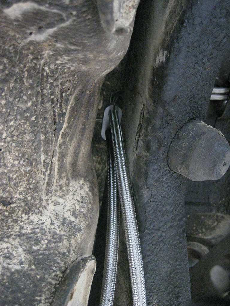
The clamp mounted through a pre-existing hole on the back of the frame.
=center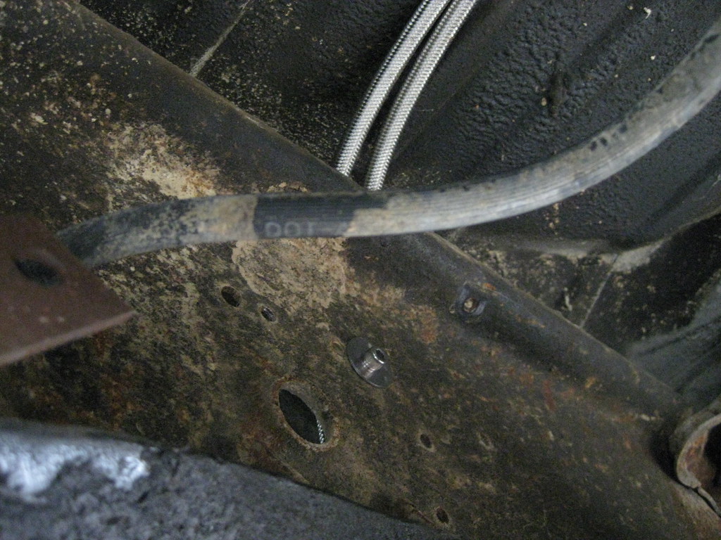
I installed the driveshaft strap, which with the new location of the driveshaft probably won't do a lot of good, but it's there anyway.=center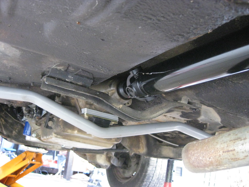
I put the bell housing cover back where it belongs.
=center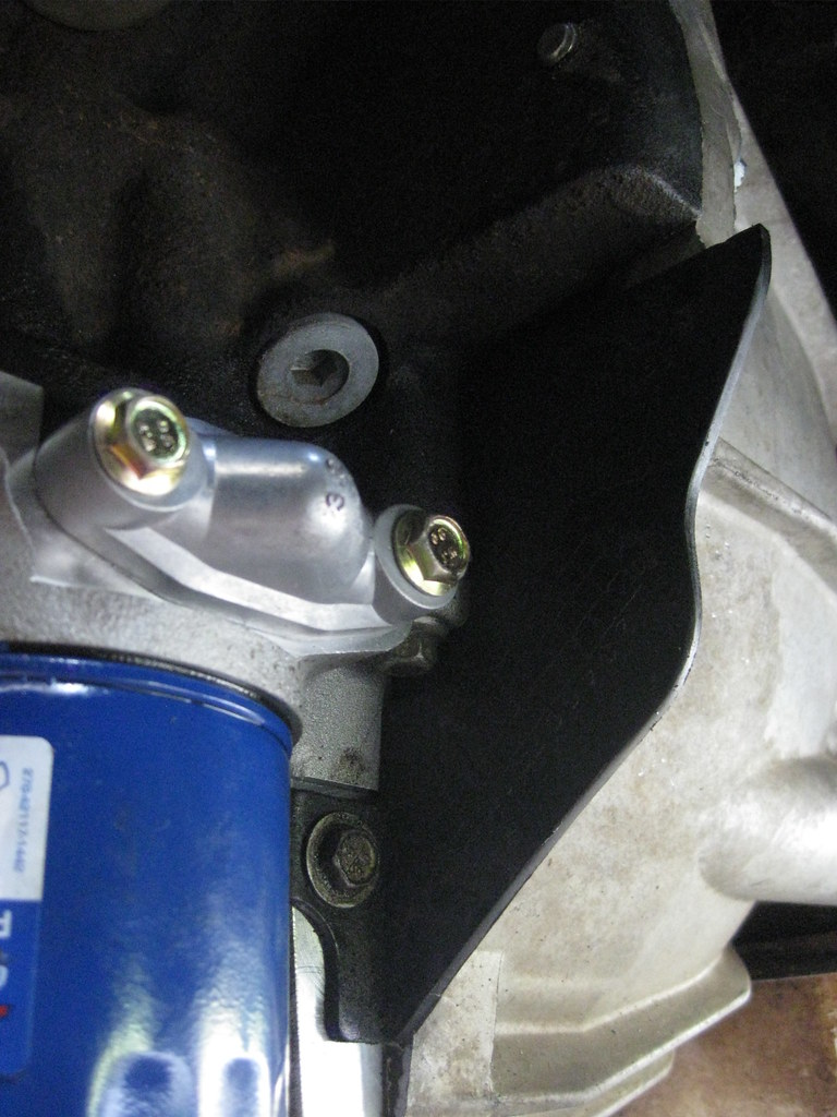
The vacuum reservoir for the HVAC system holds extra vacuum for situations where the engine may have low vacuum. This allows the systems that use vacuum to maintain constant vacuum and a consistent operation, unlike vacuum operated wipers of old that would stop working when the engine was under a load. I'll need to break off this tab to have access to a vacuum manifold port.=center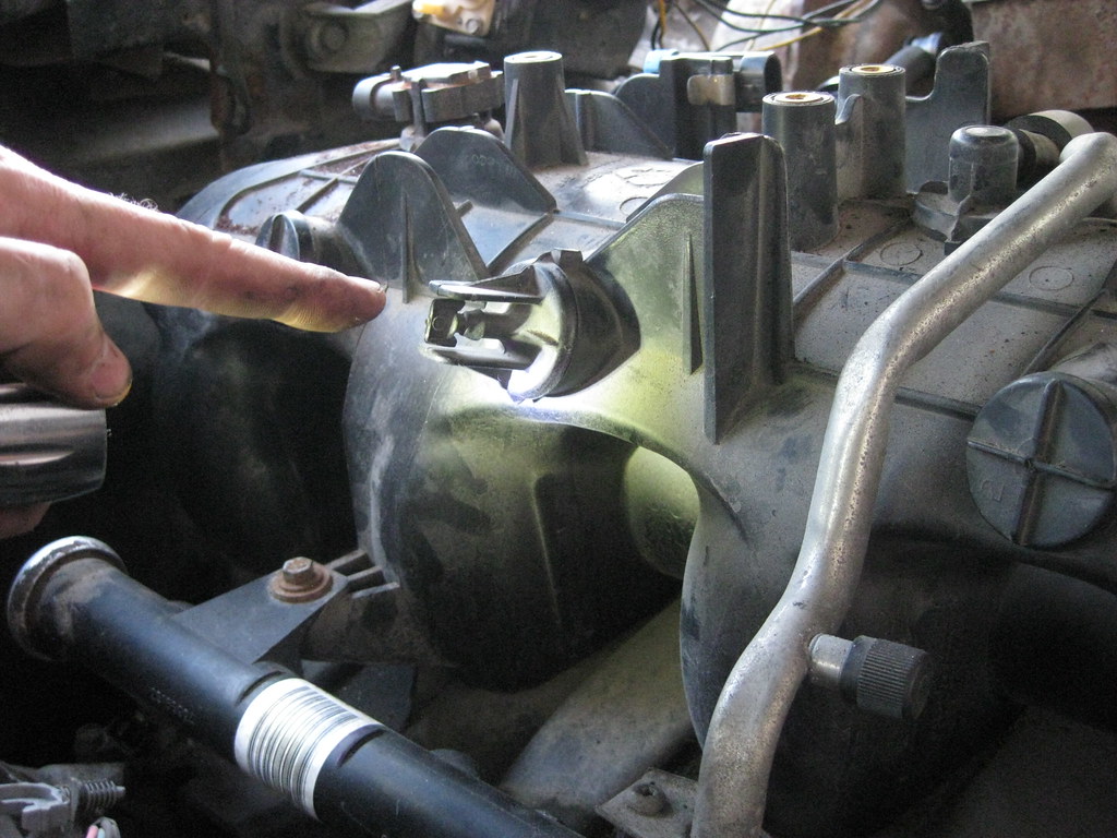

 10-14-2018, 10:50 PM
#74
I've been combing over more and more diagrams and have been working on wiring up the two electric fans using three relays. The 2004 Avalanche originally had a mechanical cooling fan. The three relay setup should allow the PCM to control two electric fans and also allow them to operate on a low and high speed. Rather than have one fan on for low and two fans on for high, this setup will allow both fans to operate at a lower speed for low, giving more cooling at the low temp as more air will be pulled through a greater surface area over the radiator core. Things started to get out of hand on the dining room table so I had to regroup and reorganize.=center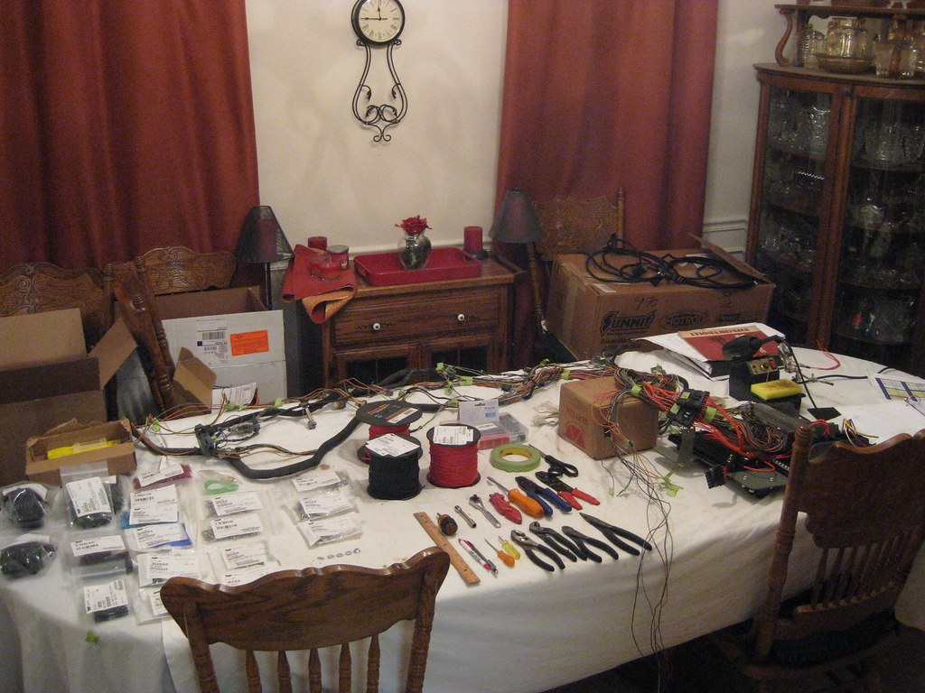
I've gotten to the point where I've had to add a few wires to the harness connector. I kept all of wires I removed from the harness because many of them had the connection on them that fits into the PCM, so I was able to repurpose those wires for things like the air conditioner and electric fans.=center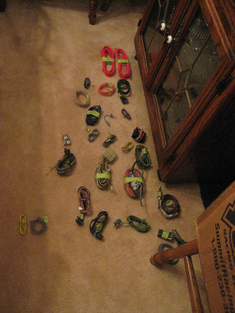
After weeks upon weeks of working in heat that was too hot I was unfortunately not surprised to find it was actually cold this weekend. I had to wear a jacket and a hat when just last weekend it was in the high 90s. It seems like the last few years we have skipped fall.
When I have spare moments I tend to sit and think about what I have left on the build. I began thinking about how the lower mounts on the radiator cause it to lean back toward the engine. It leans with enough force that it was putting some amount of strain on the upper radiator mounts when I was test fitting them. Ideally, there should be no fore or aft tension on the radiator mount. I tried to think of a way to remedy this without modifying the lower mounts but I ultimately decided I would have to remove the mounts and reweld the mounting tabs to set the radiator back. I really, really did not want to have to dig back into that project again, but I knew I had to to make it right. There was a chance the vibration from the road (or the temptation to show the girls how dad used to jump the railroad tracks) could cause the radiator to come loose from the upper mount. When I pulled the radiator out I found that the mounts were actually sitting flat against the lower radiator support. The solution was to take vise grips and to bend the entire lower support, which not only worked perfectly, but also was a much, much easier and time saving solution.=center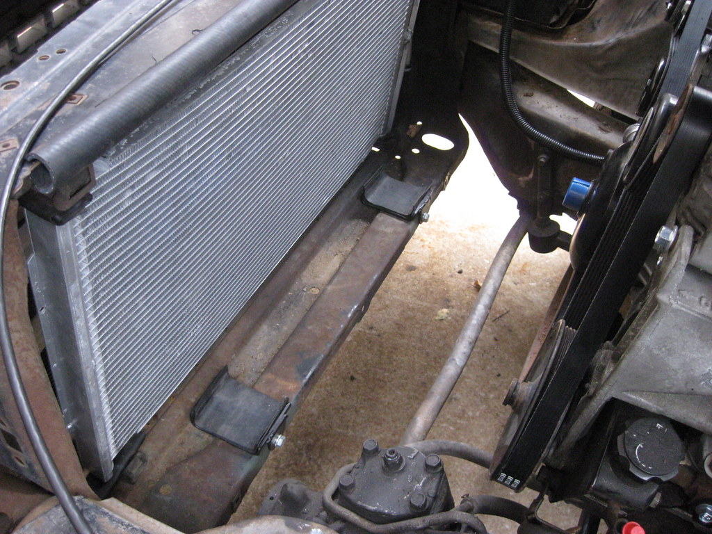
The end result is that the radiator now sits in a neutral location right against the rubber I put against the core support. This will put a lot less stress on the mounts because to pull the radiator back to where it needed to be previously took quite a bit of force.=center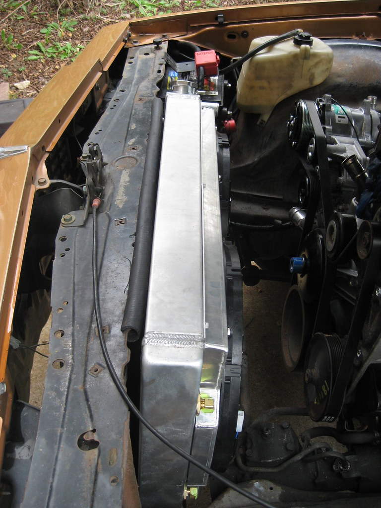
Remembering back, I had previously had the metal shop bend the metal for the upper radiator mount but the rise was not at the correct angle. I cut off the extra length of the upper radiator mount and made a template with a hammer and vise to get it close to the shape I needed the larger piece to be. I took both pieces back to the metal shop and they rebent it to match the template.=center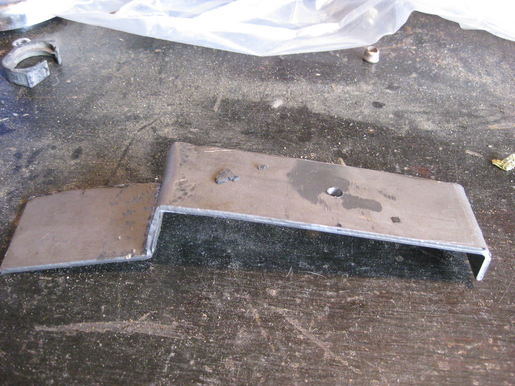
The shape of the rubber isolaters was not allowing as tight of a grip on the radiator as I would prefer so I drew out some lines and gave the corners more of a right angle.=center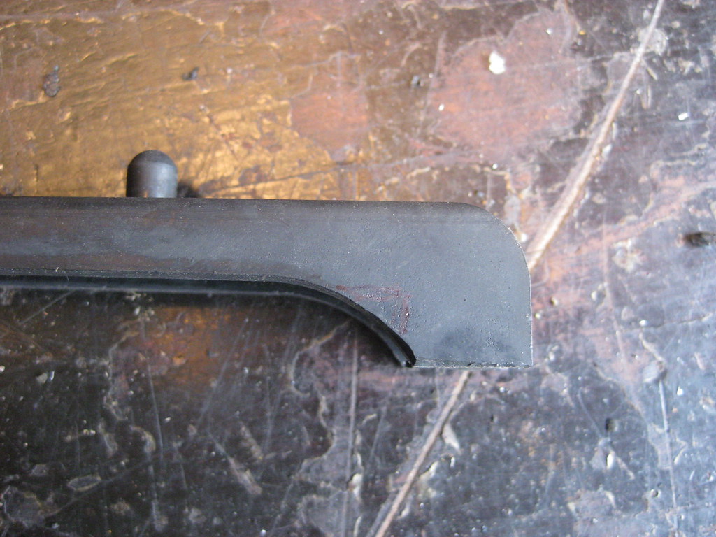
I can't remember what estate or yard sale I picked up this electric dremel, but it is about 100% better than the old pneumatic one I had.=center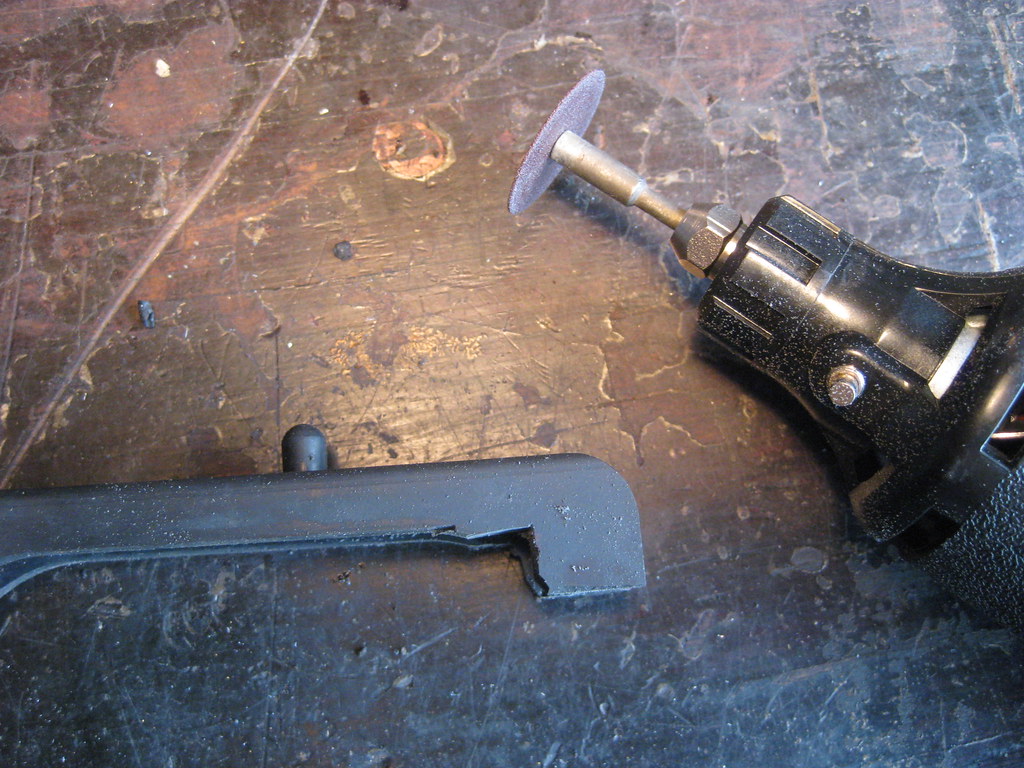
I trimmed the front and back of the isolators and the fitment and grip afterward was much better.
=center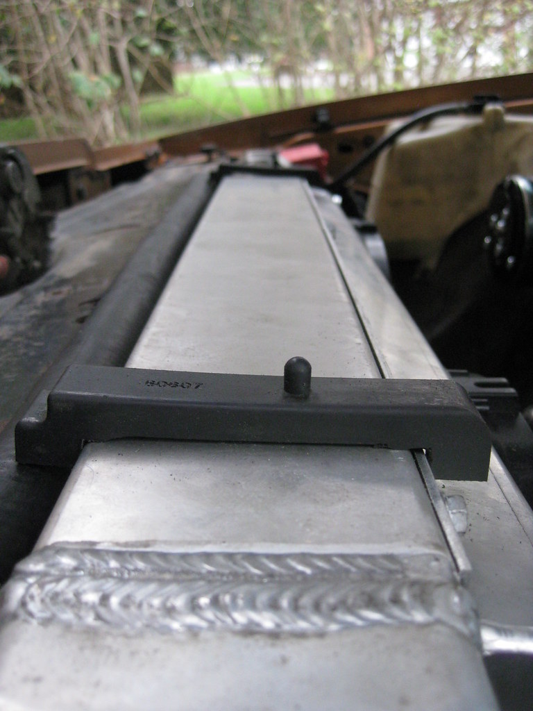
Then I had to drill the holes for the isolator mounts. These had to be in the exact right location so that the turn down on the back of the mount would hold the isolator in place and the hole would hold the nipple in place as well.=center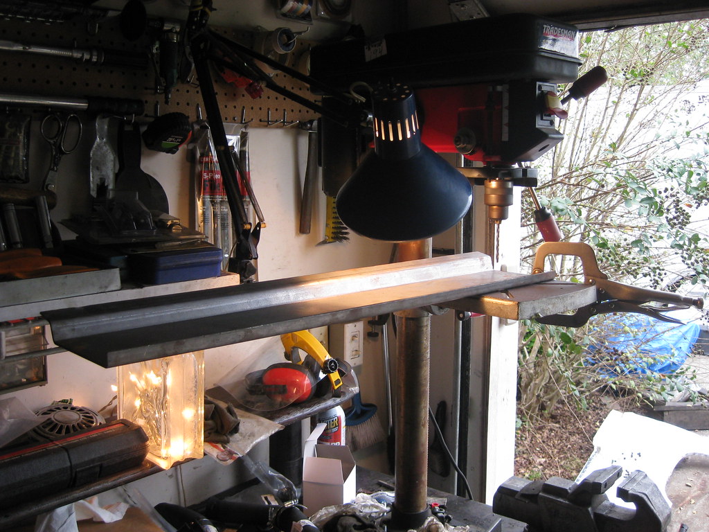
Fortunately they turned out good and I was glad because I was not looking forward to welding those holes up and starting over.
=center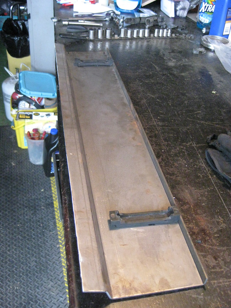
Measure 200 times and cut once with a grimace, then ask someone else to look because you don't have the nerve.
=center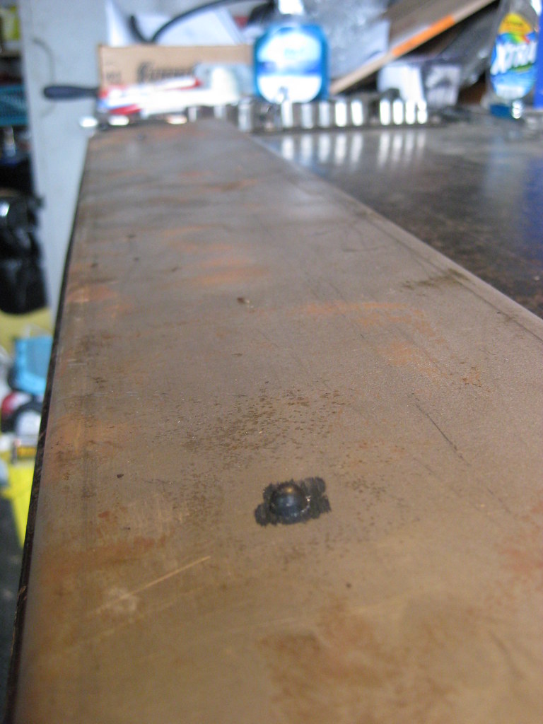
Then I trimmed a section out of the rubber on the core support for better fitment and support.
=center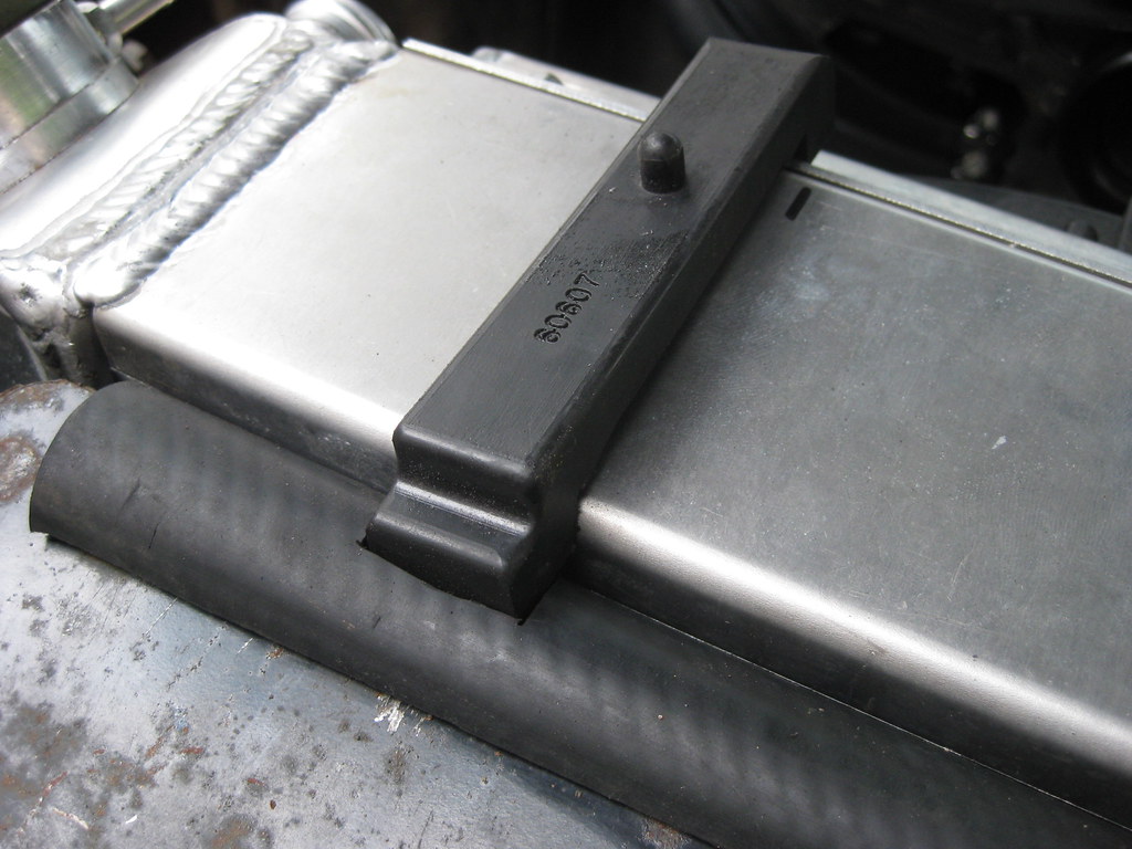
Next I had to drill the holes that would hold the radiator mount in place. The problem here was that the holes in the core support were all boxed in and I couldn't reach underneath to mark where the holes were onto a piece of cardboard. I taped a piece of paper on the area and punched the holes into the paper.=center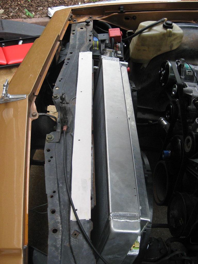
Then I transferred the holes in the paper into a piece of cardboard.
=center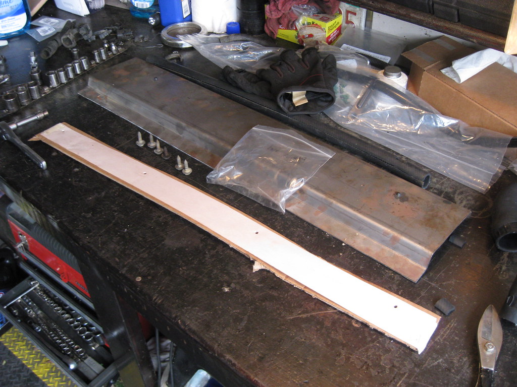
Then I test fit the cardboard to make sure they were correct. One bolt was missing and two others didn't want to thread very good so I had to run to the hardware store and got four new boolts.=center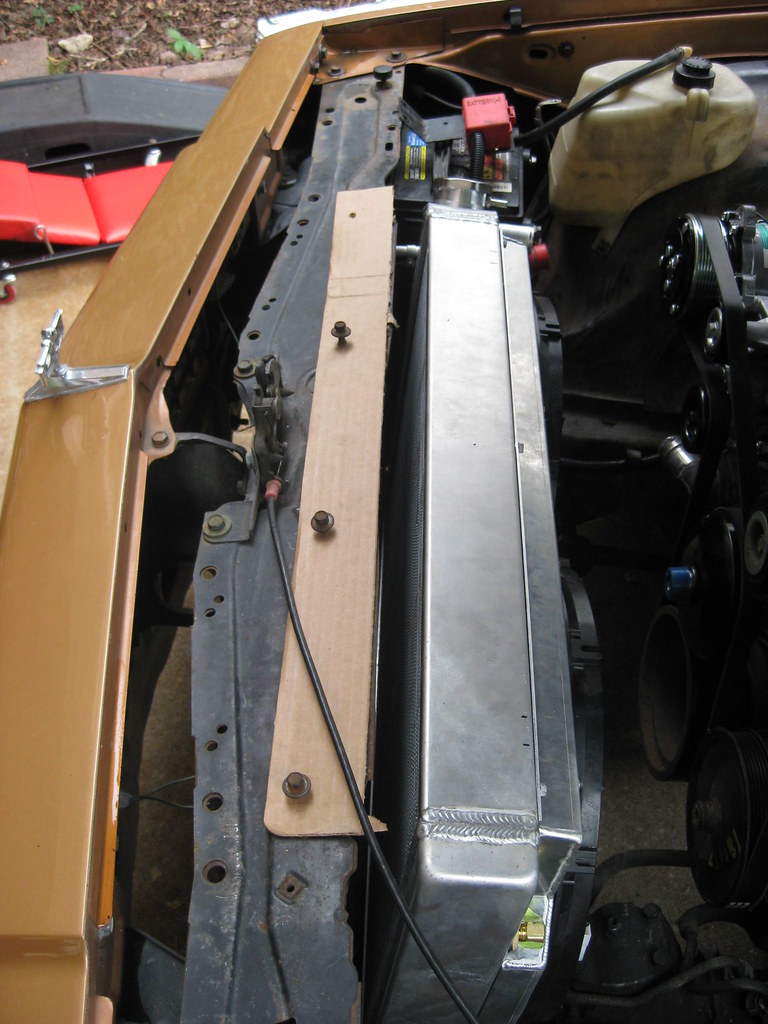
Then I transferred the cardboard onto the mount. I had to locate the far left and right hole and the middle two would fall in line. I also made a cutout for the hood spring, which on this car is attached to the hood rather than the core support. At long last, it was finished, and it fit and it hold the radiator very secure.=center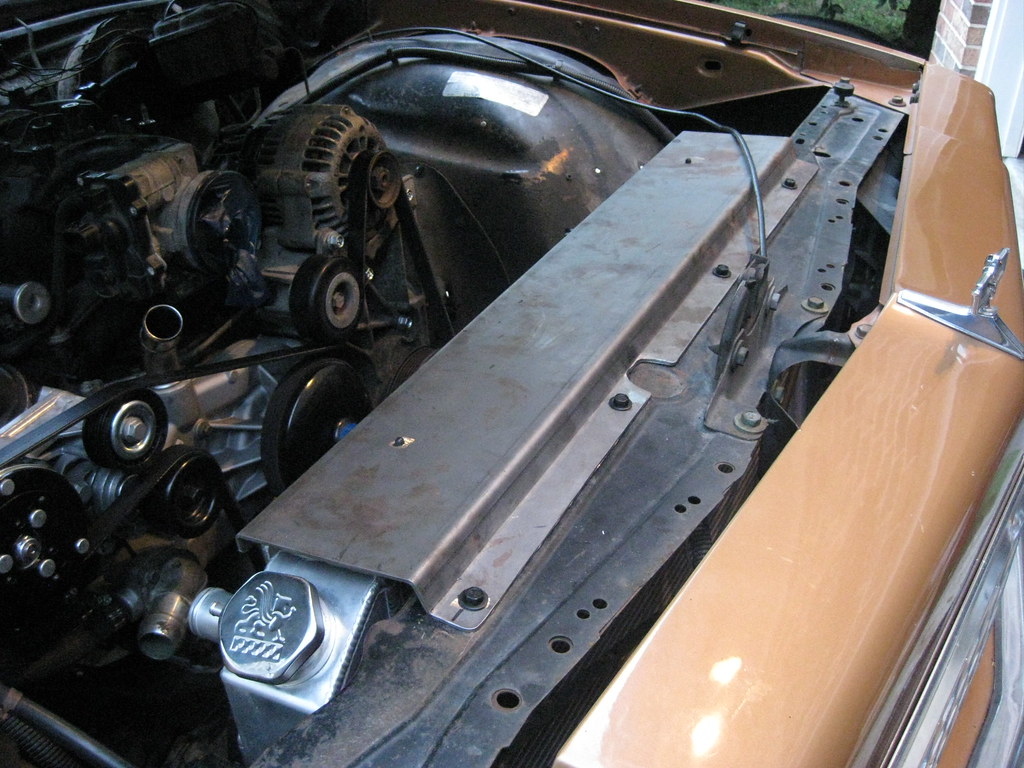
I couldn't have imagined how difficult, start to finish, this simple piece would have been. Aside from making the template, finding the steel and then finding a way to get it bent and then getting it bent to the right shape. Adding the time I've spent looking through scrapyards and trash dumpsters behind body shops to the trip into the city to buy the steel and then looking at different metal brakes, researching how to modify and upgrade them to bend 1/8" steel and ditching this idea and then calling no less than 10 people or companies trying to find a way to get it bent I can't even count the hours I have in this piece and early trips before work in the morning to the metal shop. If I had it to do over, now that I have it all figured out, it wouldn't take 1/10 of that time.=center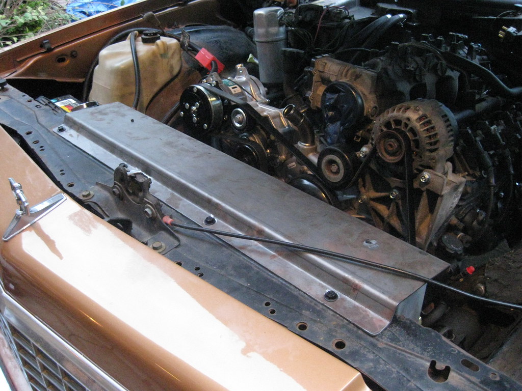
It would have been easier to run two arms over the top and mounted the radiator that way, but I like the look of these type mounts much better. Also, many of the other mounts I have seen are hard-mounted straight from the core support into the radiator with no rubber isolators. That may work fine on weekend toys but on a car I've had for 21 years and plan to continue to daily drive for several hundred thousand miles on I feel this was a better long term solution. I really wanted to laser cut a Caprice emblem on the top with etched colored glass under the holes and then put two colored LEDs under the mount that would have come on when the hood was raised but in my effort to again not go overboard I had to decide not to. I haven't yet decided if I want to have some bead rolls put into the piece. The piece is sturdy enough that I don't need them for strength, but if I decide I want to later it will be easy enough to remove the four bolts and have the metal shop run some beads.=center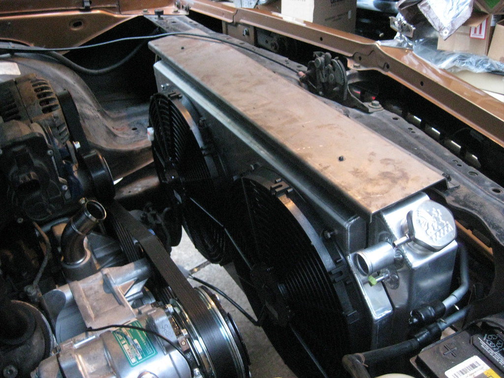
10-14-2018, 10:50 PM
#75
The brake flaring tool finally came in. This is the most money I have ever spent on a tool, and hopefully ever will, but after every rental flaring tool in town proved to be garbage I knew I had to buy a decent one. Over the years I've done enough hose fittings to know I'll do more. Just last year the 60 Cadillac had to have two new front wheel cylinders (which was done in haste and not documented in this blog) and I had to cut the line off the care and reflare it. This would have made that job very easy and would have allowed me to do it on the car. I also know that when I spent all the time it's going to take to bend these transmission lines and snake them all the way back to the transmission I'm not going to want to risk a bad flare ruining the whole line and it was important it be made right the first time. After years of frustration I am finished using garbage flaring tools.=center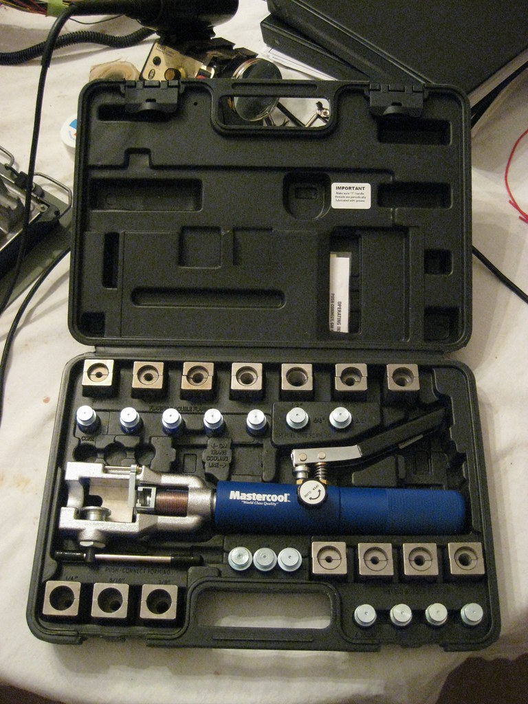
The tool works like this. Clamp the right size die around the line. Put in the first fitting and squeeze the hydraulic line.
=center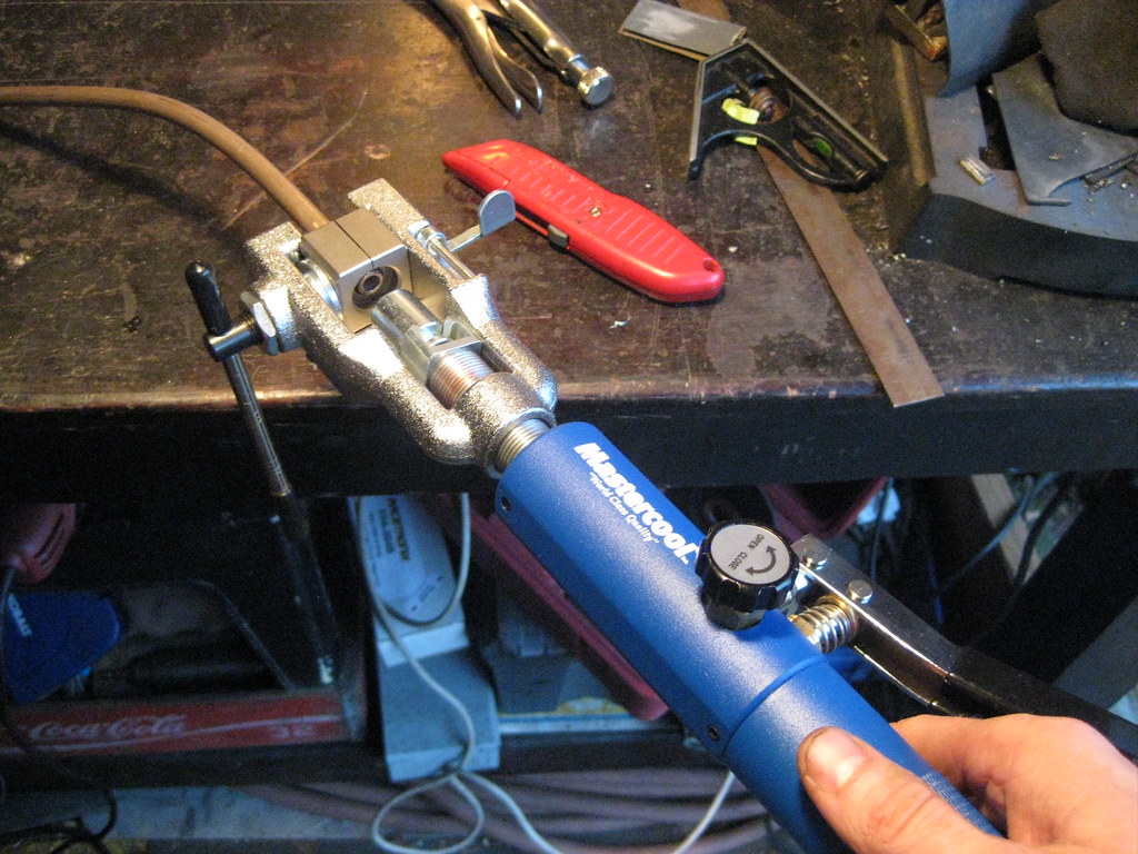
Release it and install the second fitting and repeat the process.
=center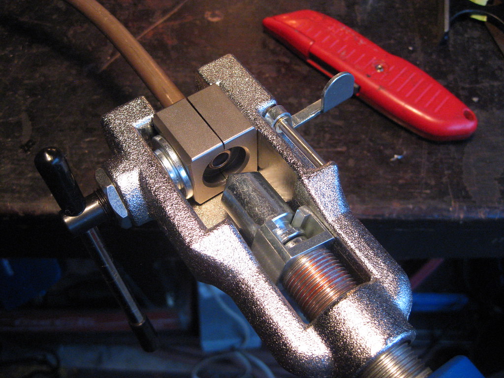
Every time it makes a perfect flare. And yes, by the time I got the line bent and was ready for the second flare I was losing daylight and in a hurry and frustrated from the difficulty of bending line and forgot to put the fitting on the flare not once, but twice.=center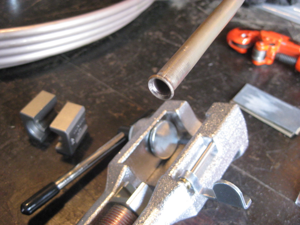
In the end for me this was well worth it. It also does a lot of other types of fittings as well.
=center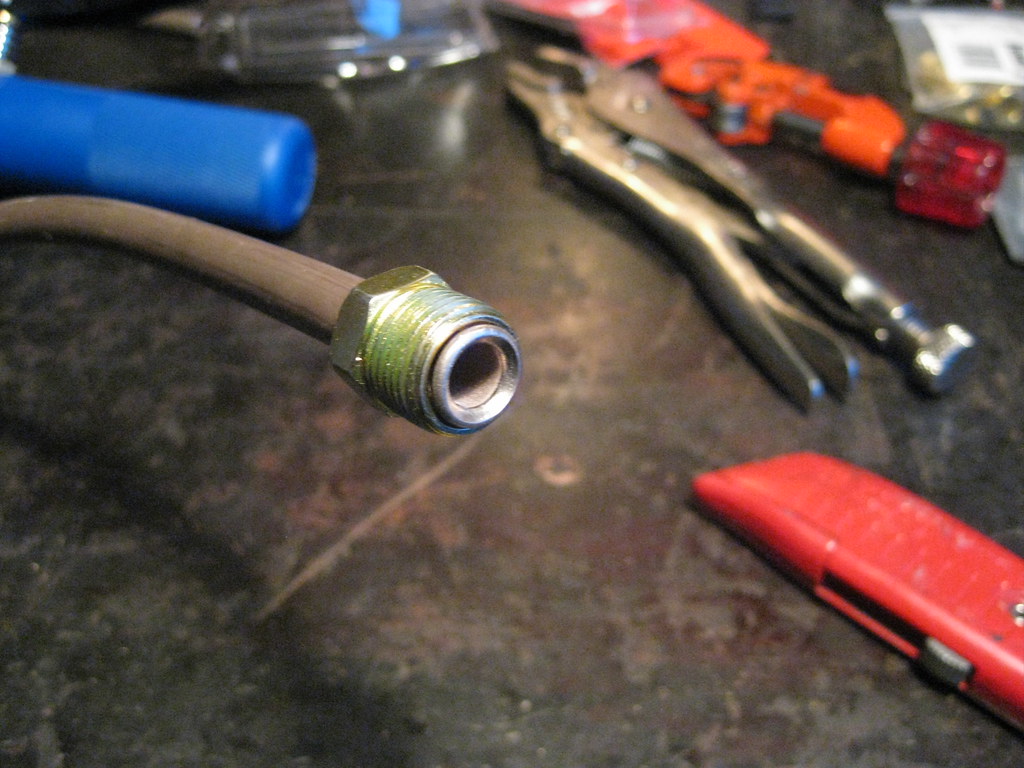
When it came time to bend the line I first tried using a coat hanger and then match those angles. Since I didn't know how long the line needed to be, and I was afraid of running out, I had to try to bend the line while keeping all the rest coiled on the end. I found that doing this as one person was practically impossible. I had bought this bending tool at a parts house when I was running all the line on the '37 Chevrolet. This tool was utter garbage and broke almost immediately back then when I first got it. I kept parts of it thinking I might use them in the future. It again proved to be virtually useless. I think I put about 50 miles on my creeper trying to determine the best route to run the lines. I finally was able to get one of the lines bent and fully installed. Once I finish the second I can install the transmission dipstick and have the exhaust installed as well.=center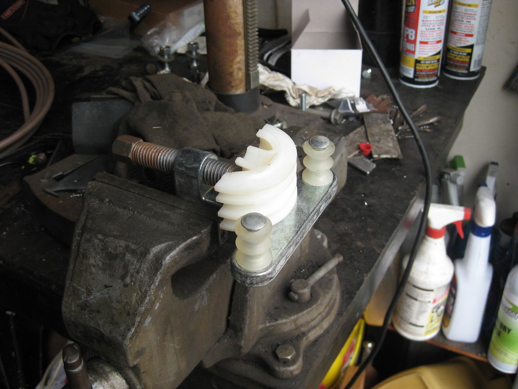
10-15-2018, 07:09 PM
#76
TECH Addict
iTrader: (19)
Join Date: Aug 2007
Location: Where the Navy tells me to go
Posts: 2,397
Received 106 Likes
on
88 Posts

That radiator upper bracket I think will hold the entire car together!
10-18-2018, 03:47 PM
#80

None of the MasterCool sets have both 45 and 37 degree in one kit. There 8 different kits with different type of flaring dies. For myself I bought 7145 universal kit, then bought part 71098 which are the 37 degree flares for AN. BTW this system is marginal for stainless steel lines. I cracked a couple of dies while doing SS. All of the dies are available separately so you can start with one of the universal kits, then add whatever special dies you need one at a time.