
68 Camaro Build with a Gen V Swap


 06-07-2019, 12:09 AM
#102
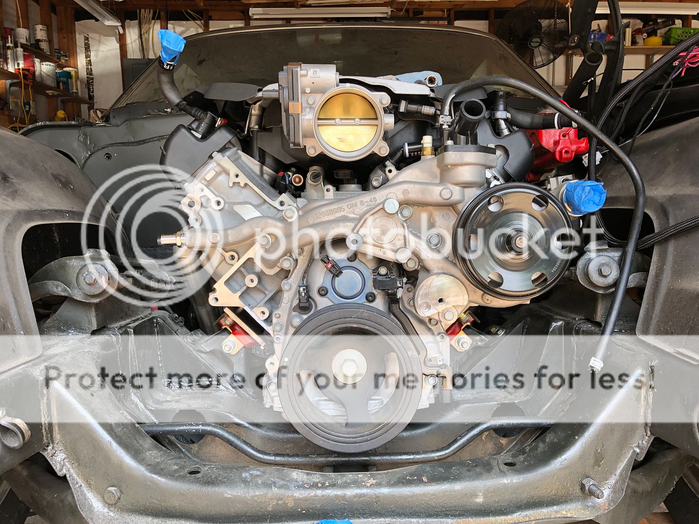
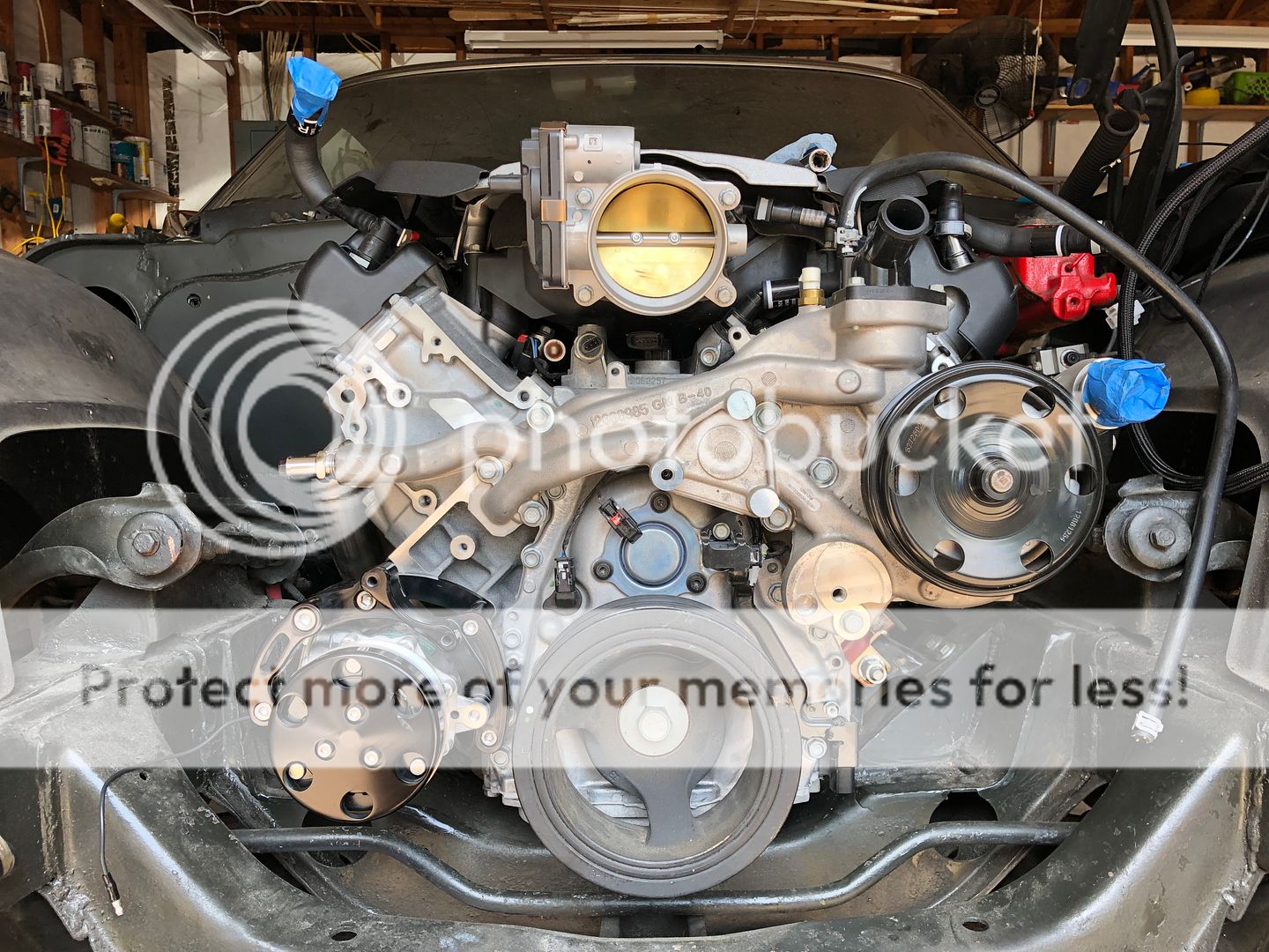
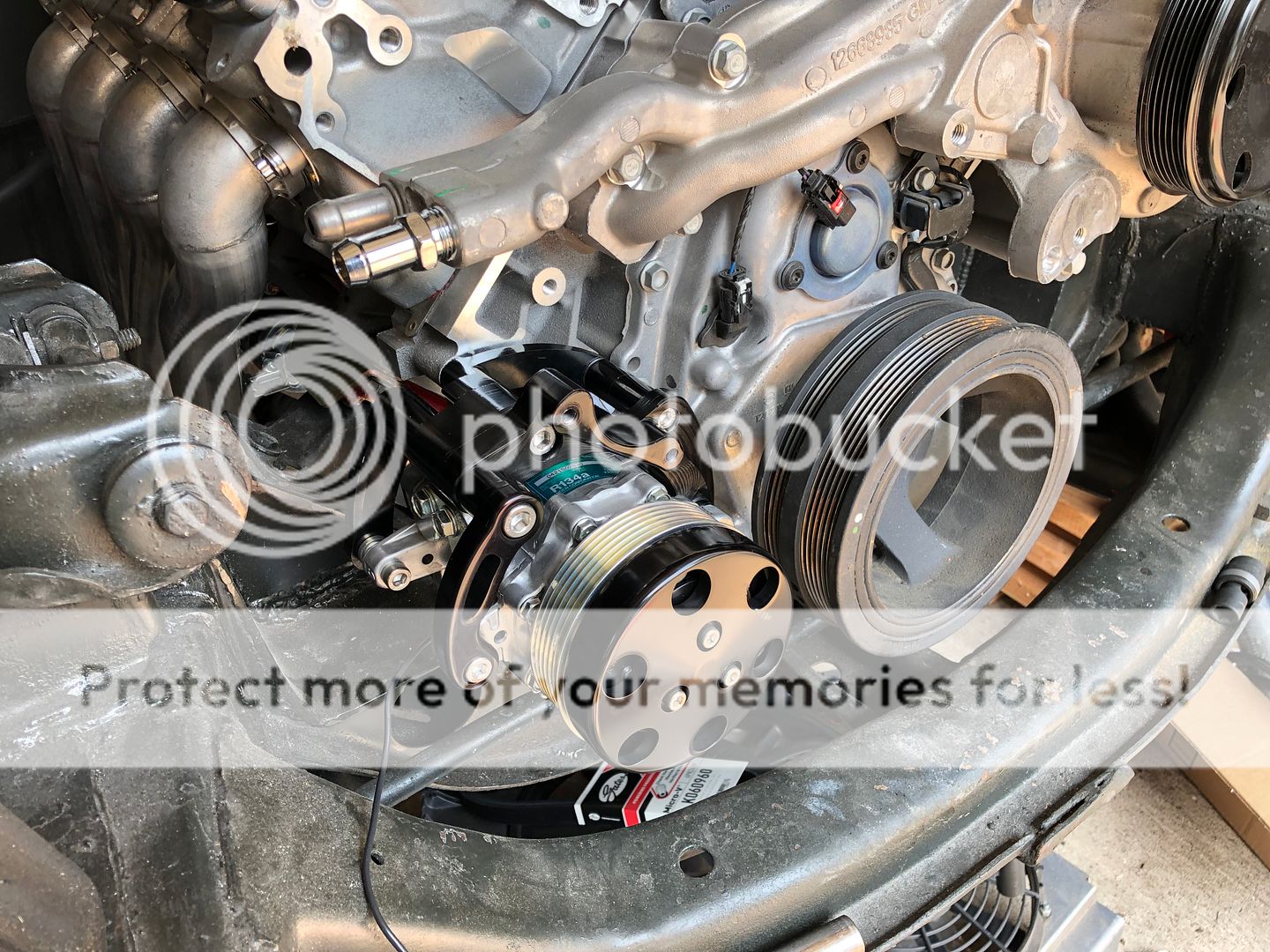
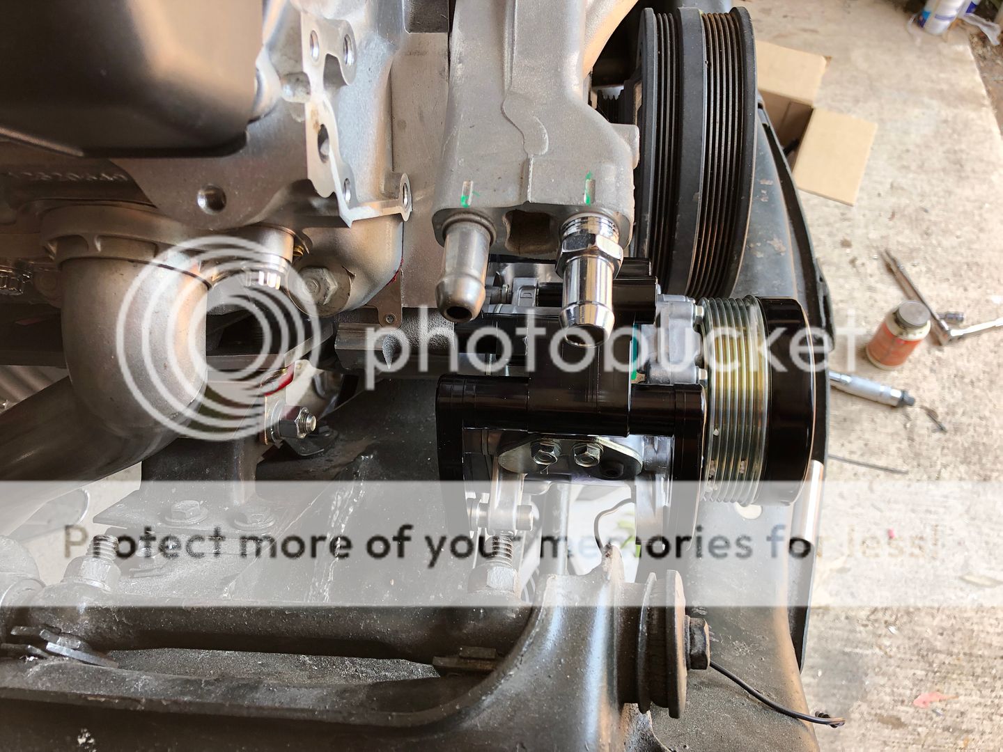
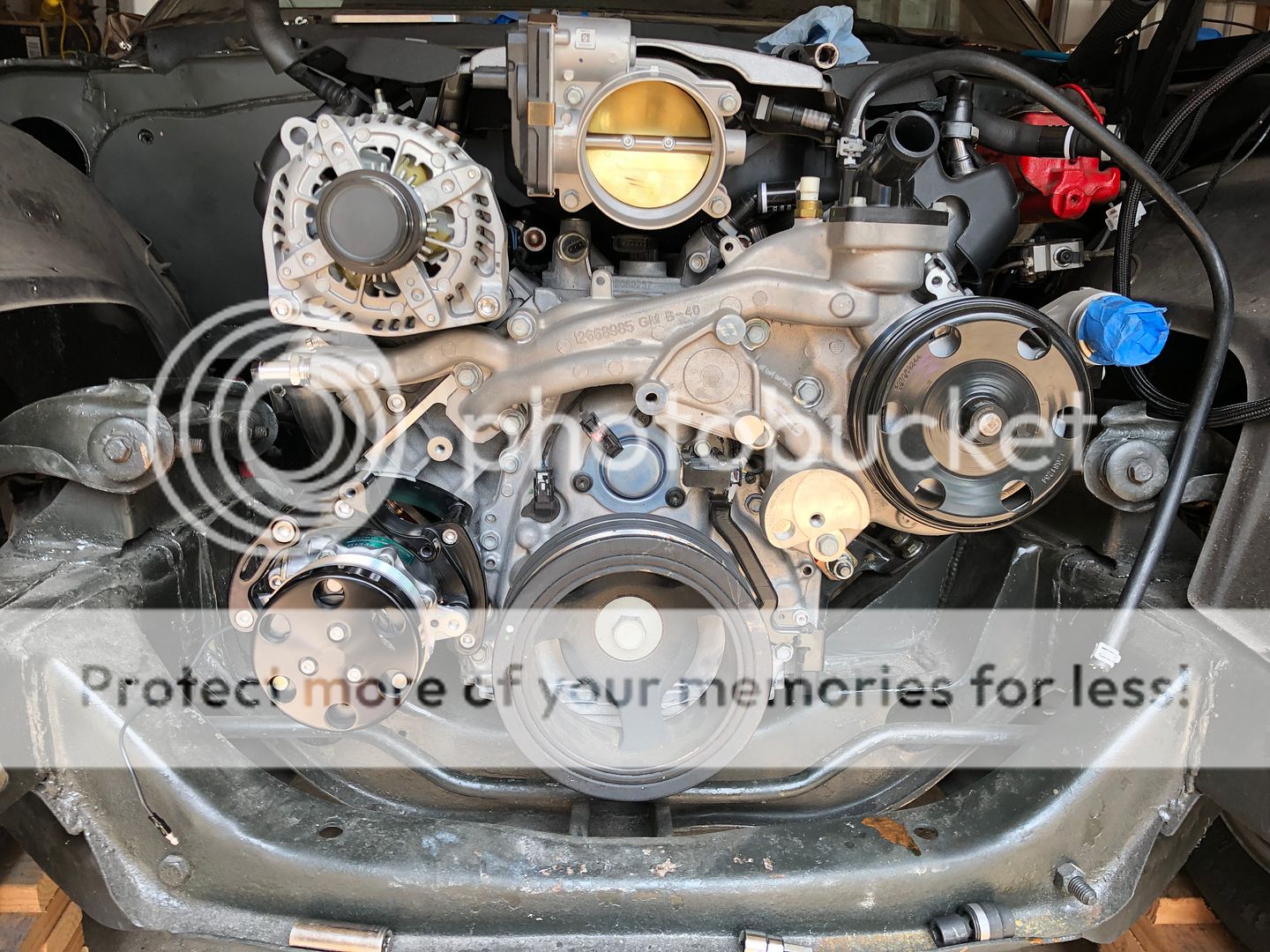
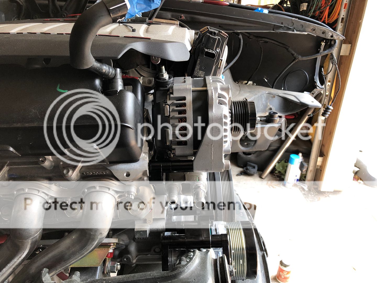
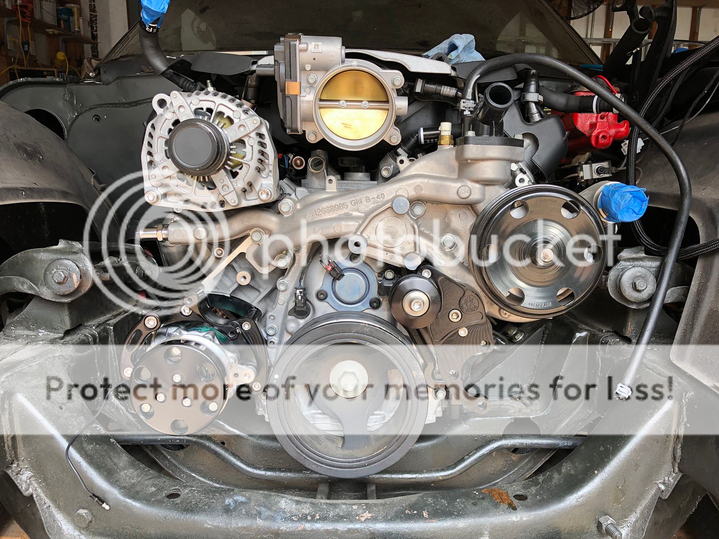
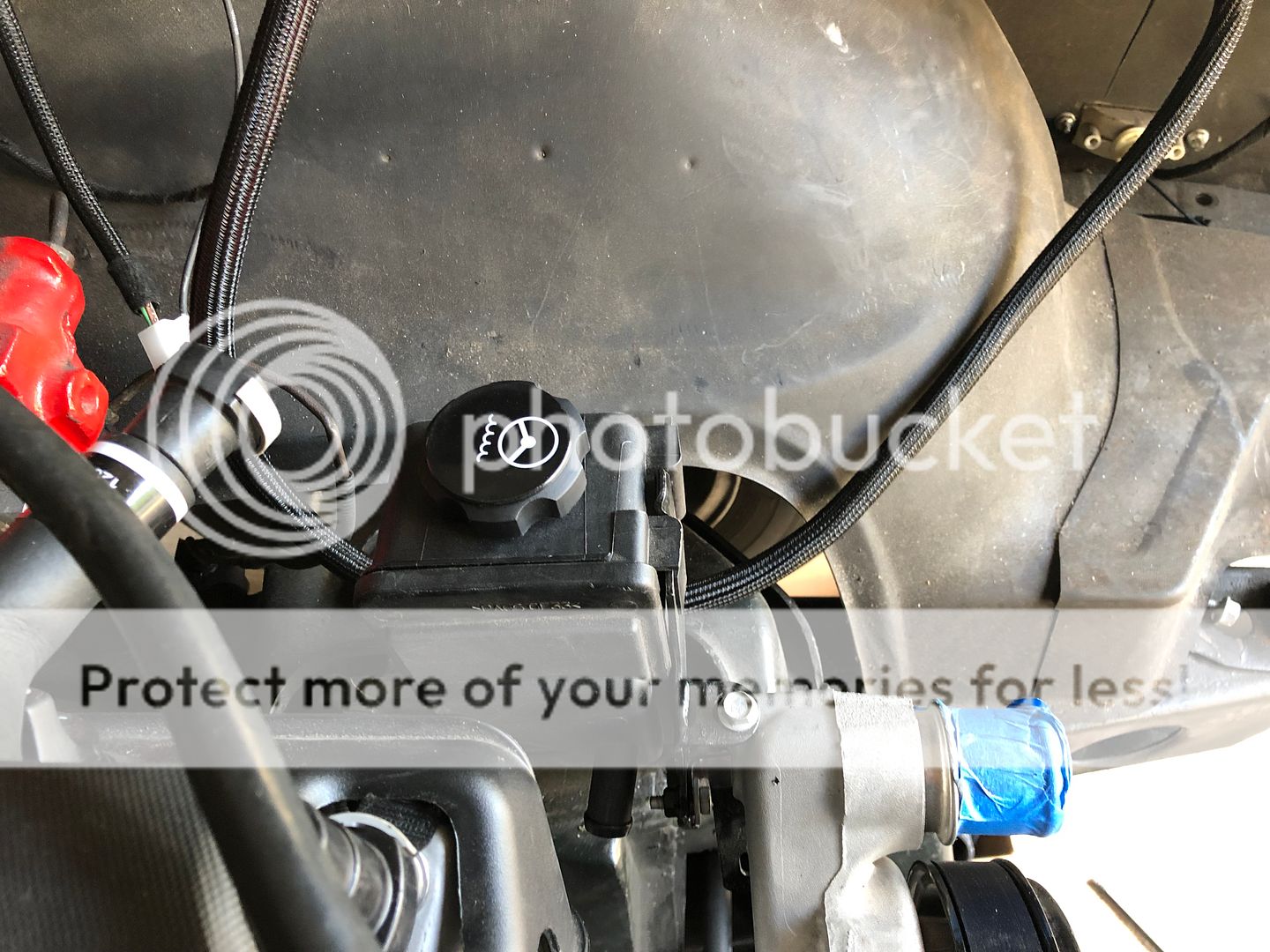
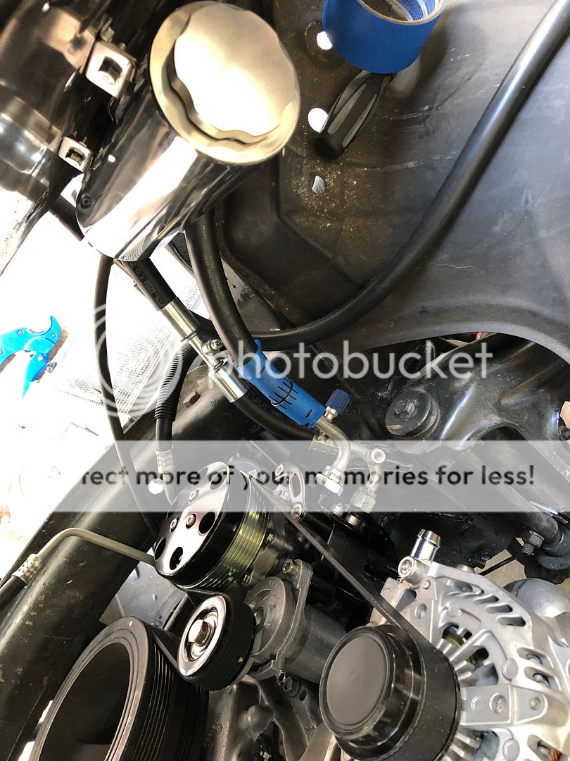
I got my new Drive Junky accessory drive in and installed it. Heres a few pictures of it as I installed it. Came with great instructions and all the parts are top notch!
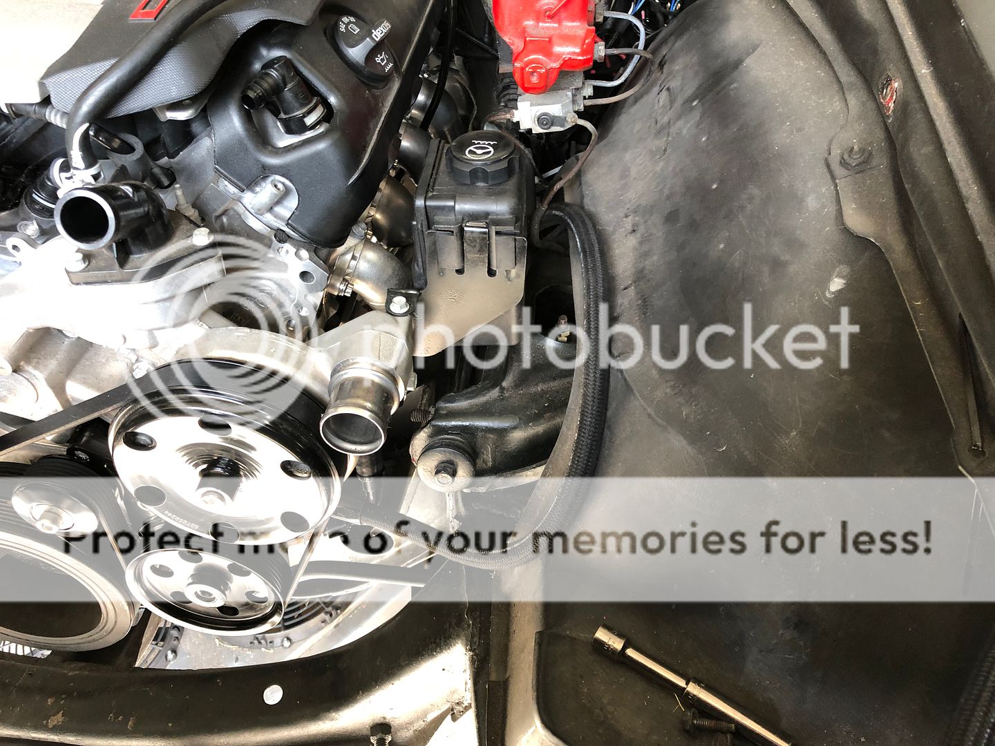
I had originally tried to use the ICTbillet PS bracket and purchased a GM pump and reservoir to use with it but the bracket did not fit. I'm left with an extra pump if anyone needs one? I ended using the reservoir and modified the bracket to fit my water pump. I'll run the PS lines in a couple weeks. Kink of sucks that I mounted my battery in the trunk already, looks like I have enough room to mount it behind this mini Sanden compressor where I notch my frame for the stock compressor..

I had originally tried to use the ICTbillet PS bracket and purchased a GM pump and reservoir to use with it but the bracket did not fit. I'm left with an extra pump if anyone needs one? I ended using the reservoir and modified the bracket to fit my water pump. I'll run the PS lines in a couple weeks. Kink of sucks that I mounted my battery in the trunk already, looks like I have enough room to mount it behind this mini Sanden compressor where I notch my frame for the stock compressor..


 06-14-2019, 06:24 PM
#104
I'm hoping to get it started by late August or early September. I'm not lacking too much, just need exhaust and to finish wiring up the engine. There are still plenty of little things too like the fuel line and rear brakes but that not too bad.
06-14-2019, 06:46 PM
#105
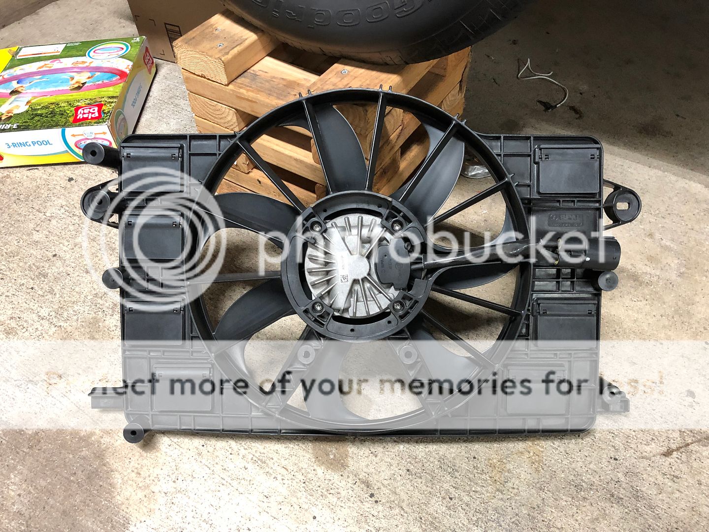
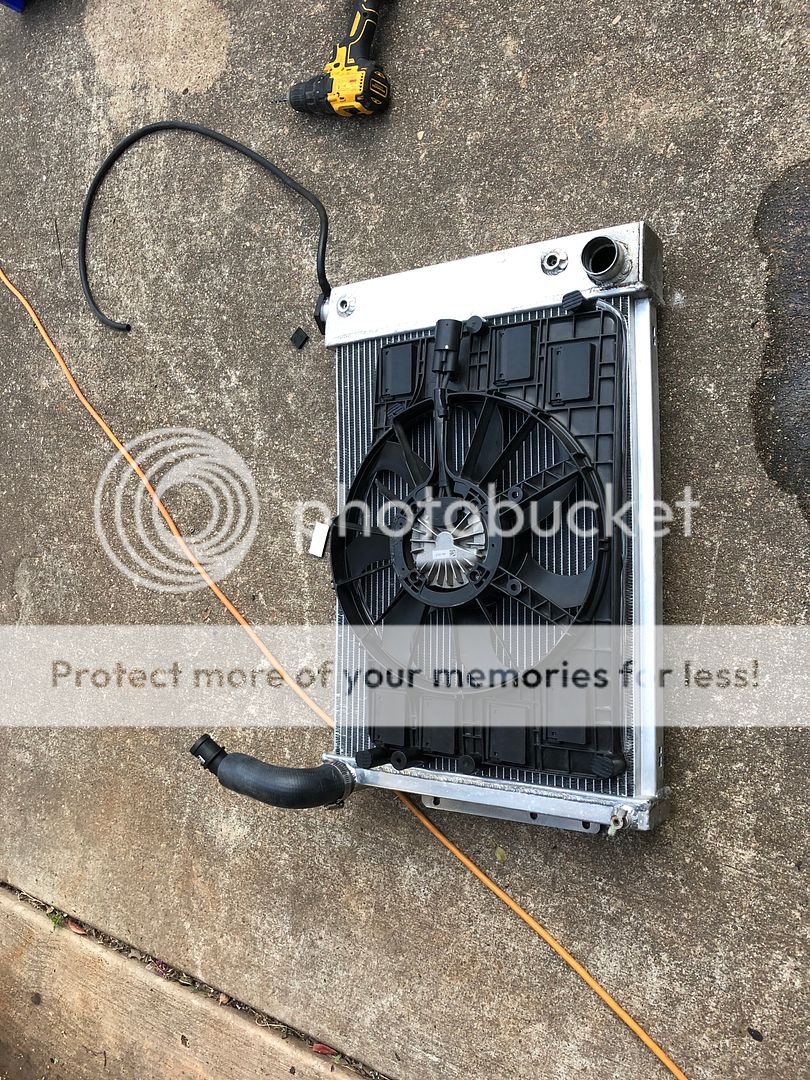
I spoke to my harness builder/tuner and he suggested I use a PWM fan from a 6th gen camaro. The PWM fan is the easiest fan to setup and works well with the gen v stuff. From what I have read the ECM does not send out a reliable signal for a relay to activate traditional fans and the signal sent out is a pulsed signal. The best way to run traditional fans is with a temp sensor and a trinary if using AC.
I was unable to find a 6th gen camaro fan for a reasonable price so I went with a C7 fan. Truck fans are also an option but they are a little too wide for my car. I spoke to Spal and they do not sell a shroud for this fan to so I ended up using the shroud that came with the fan. In order to use this shroud I had to cut off about 3/4" of the outside rim to let the fan sit closer to the radiator and make room for my intake. Added some rubber hose sliced down the middle to help get a better seal against the radiator. I also had to trim a little off around the fan blades to clear my intake piping. The fan assembly exposes a little bit of the radiator at the top, this should not be an issue as the C7 vetts have a ton of exposed area on their setups too. I used 4 ziptie style radiator fan hold downs to mount the assembly but I might add more reinforcement later.
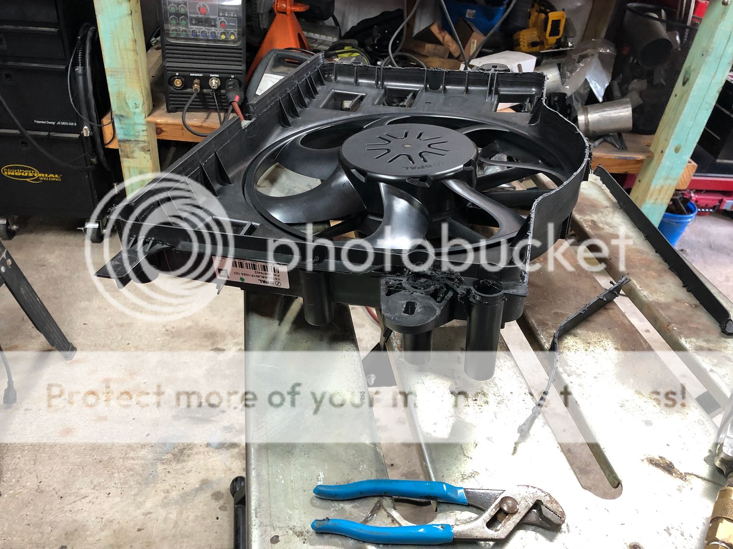
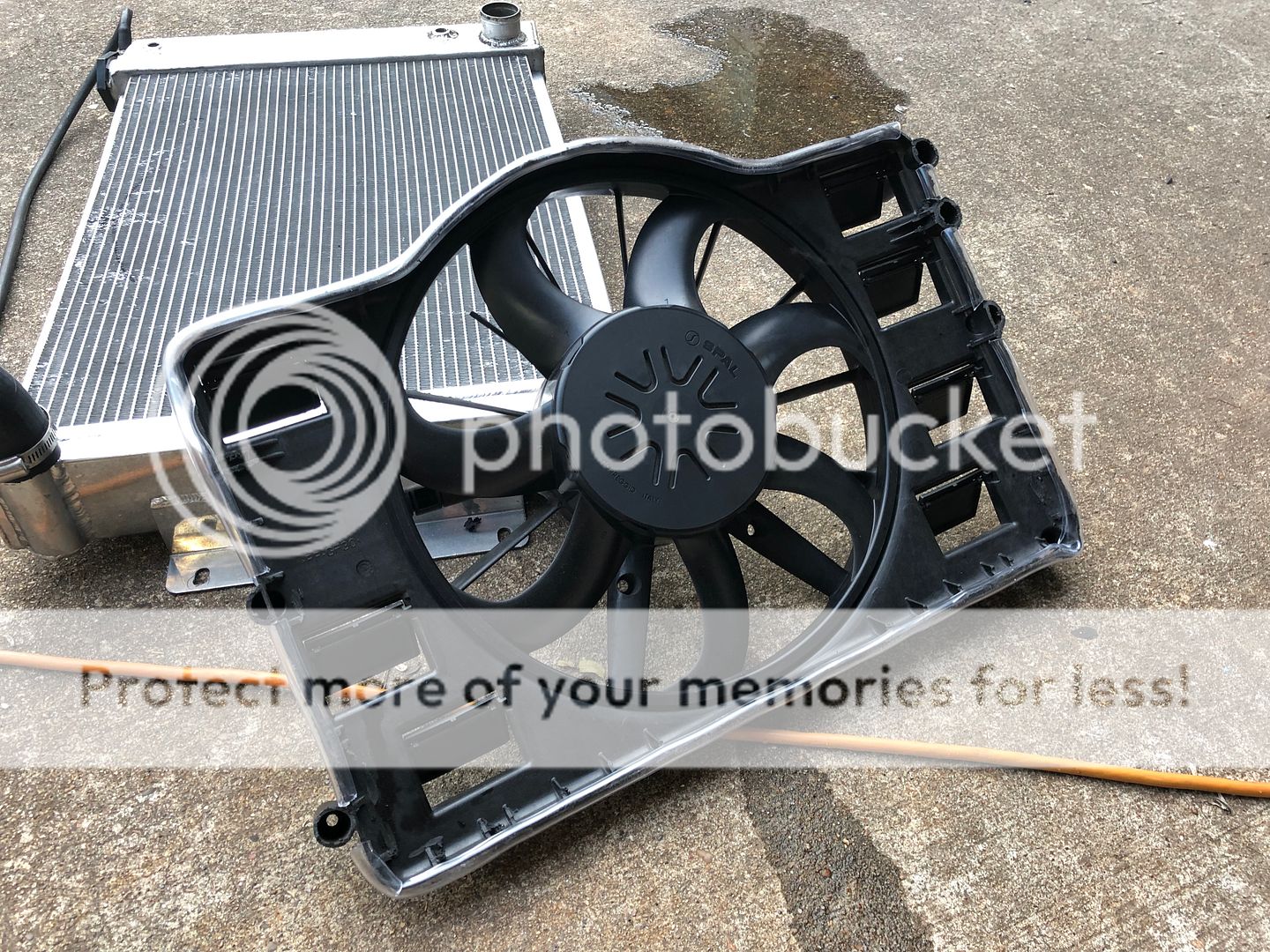
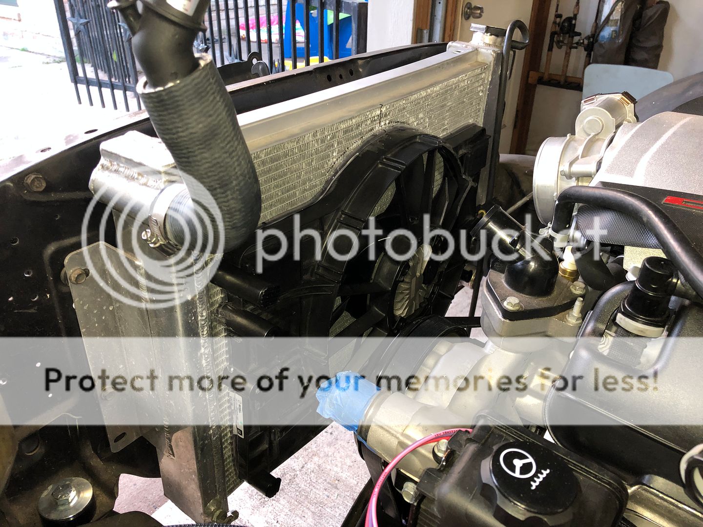
I was unable to find a 6th gen camaro fan for a reasonable price so I went with a C7 fan. Truck fans are also an option but they are a little too wide for my car. I spoke to Spal and they do not sell a shroud for this fan to so I ended up using the shroud that came with the fan. In order to use this shroud I had to cut off about 3/4" of the outside rim to let the fan sit closer to the radiator and make room for my intake. Added some rubber hose sliced down the middle to help get a better seal against the radiator. I also had to trim a little off around the fan blades to clear my intake piping. The fan assembly exposes a little bit of the radiator at the top, this should not be an issue as the C7 vetts have a ton of exposed area on their setups too. I used 4 ziptie style radiator fan hold downs to mount the assembly but I might add more reinforcement later.


 06-14-2019, 07:48 PM
#108
07-19-2019, 10:10 AM
#109
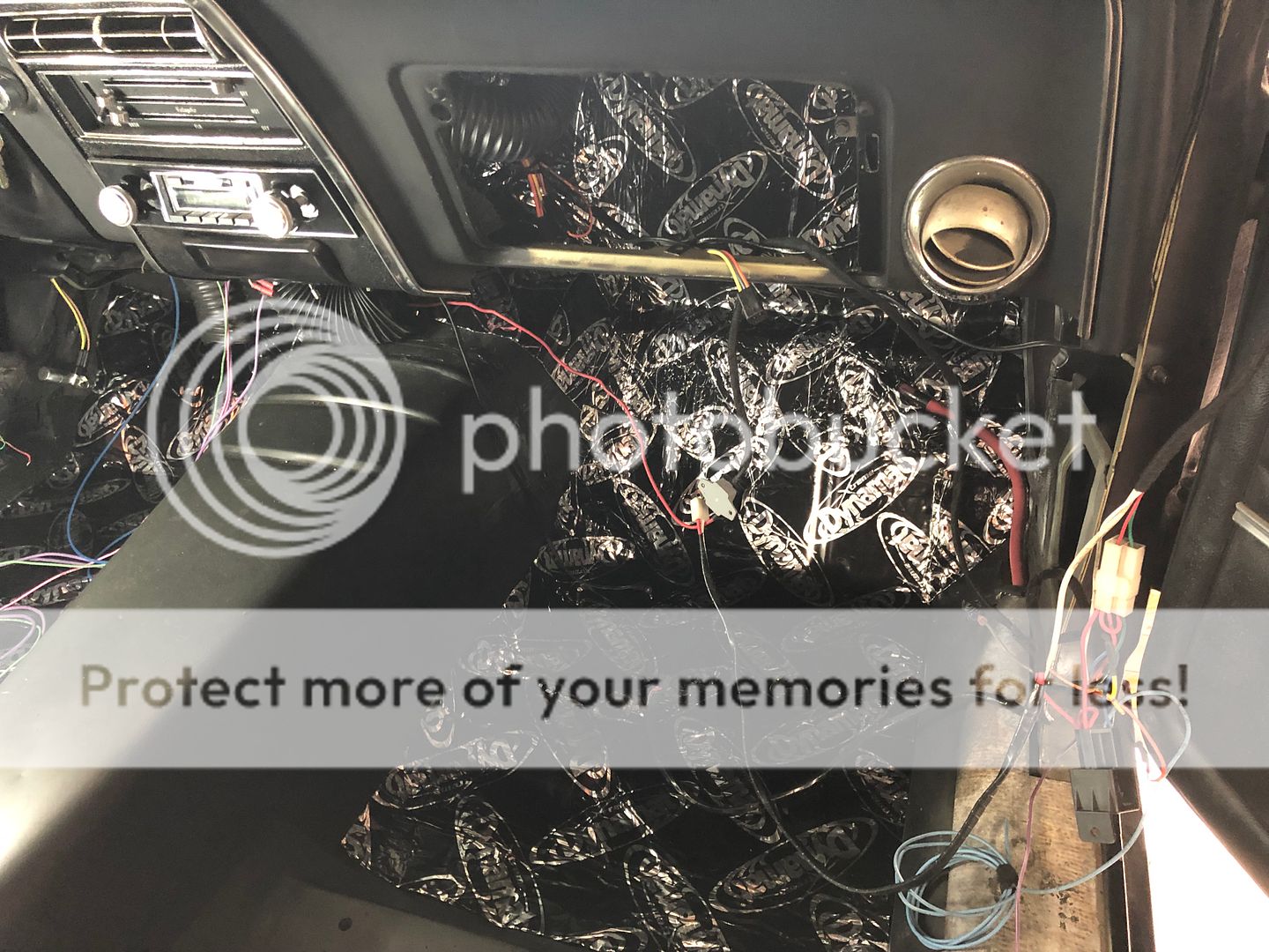
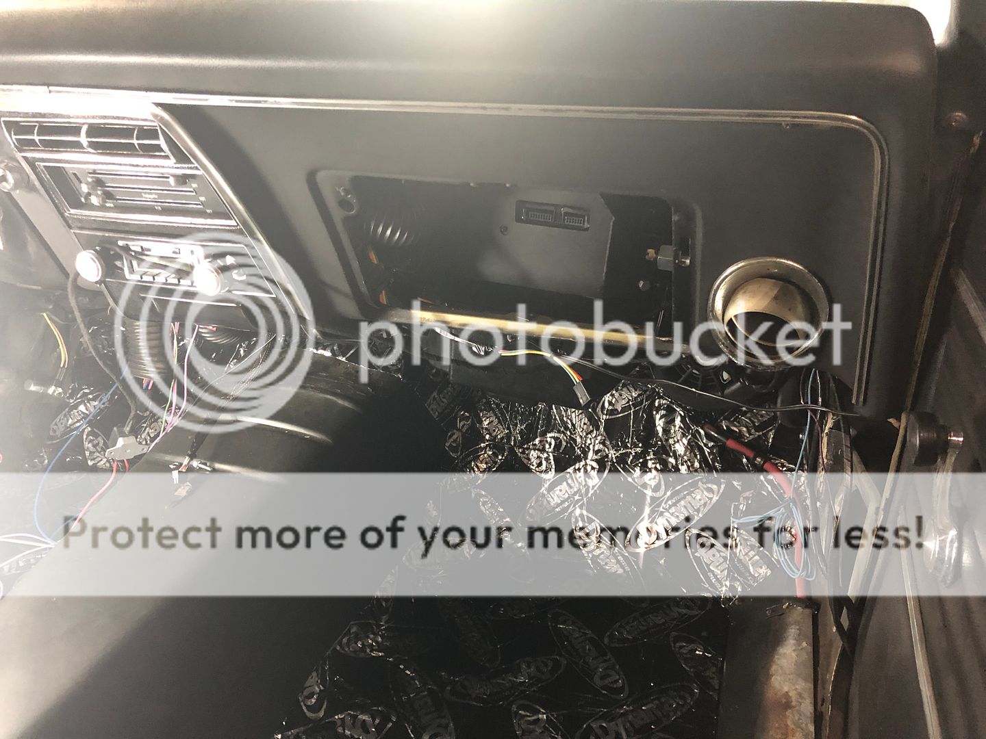
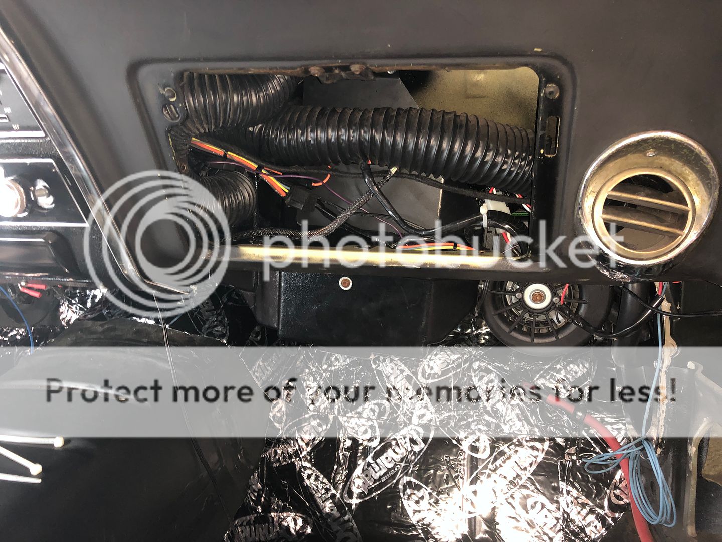
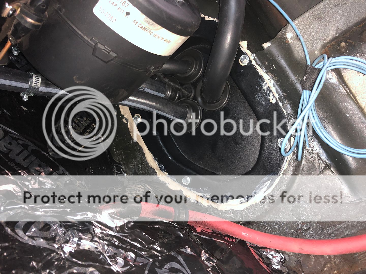
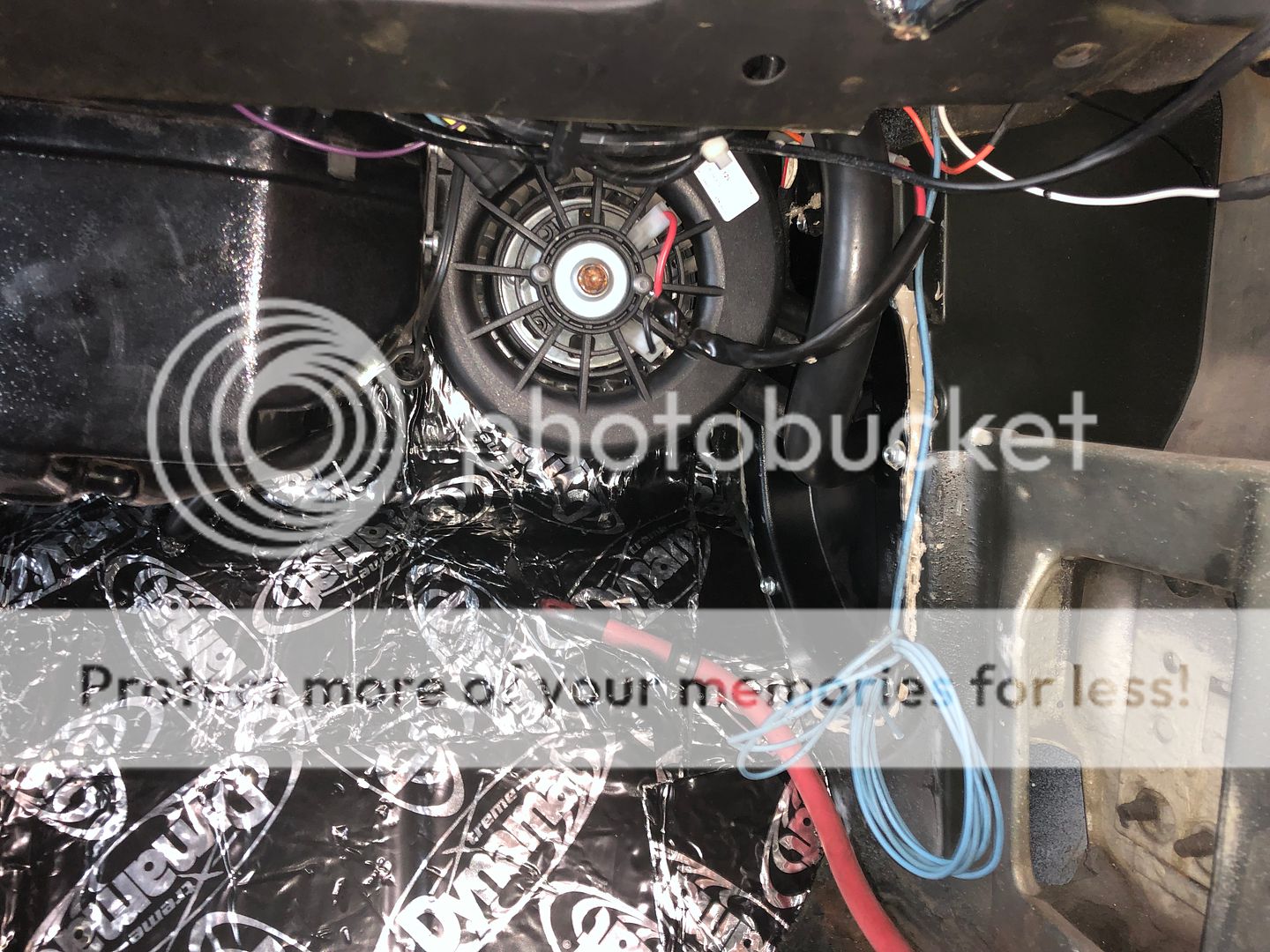
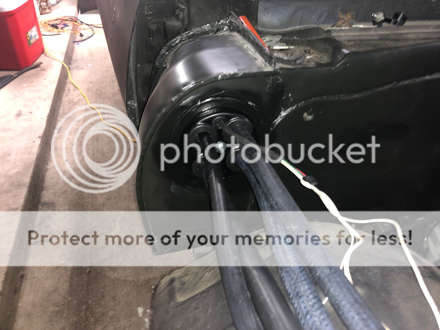
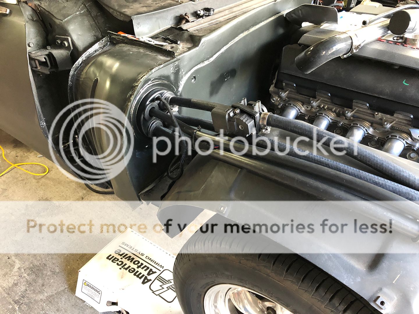
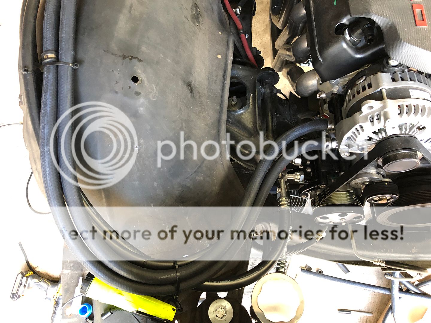
I started working on the AC lines at this point. I purchased a VA hose kit to replace my old lines that would hide my lines behind the fender. Got the wiring all done up and integrated it into my AAW harness. Still need to wire up the compressor wiring once I get my engine harness. BPautomotive hooked me up with the correct fittings to run the GM pressure switch and this was installed as well. Heres some photos of the process, it was not fun and there is very little room for the AC fan with the raised tunnel. Got everything all sealed up from water with some leftover house window sealant. Also had to be very careful with the compress fittings and rout them the best I could to have room to install the high and low pressure AC fittings on them when its time to charge the system due to the a-arm clearance but it worked out and tested fine.


Last edited by jasonz28camaro; 07-19-2019 at 07:36 PM.
07-19-2019, 07:29 PM
#112
The valve worked fine before so hopefully it still does. The fender is already on but not gapped nor fully tightened. I plan on getting everything functional prior to reinstalling the front grill and all so the fender will come back off easily. Thanks for looking out though.
07-20-2019, 08:59 PM
#113
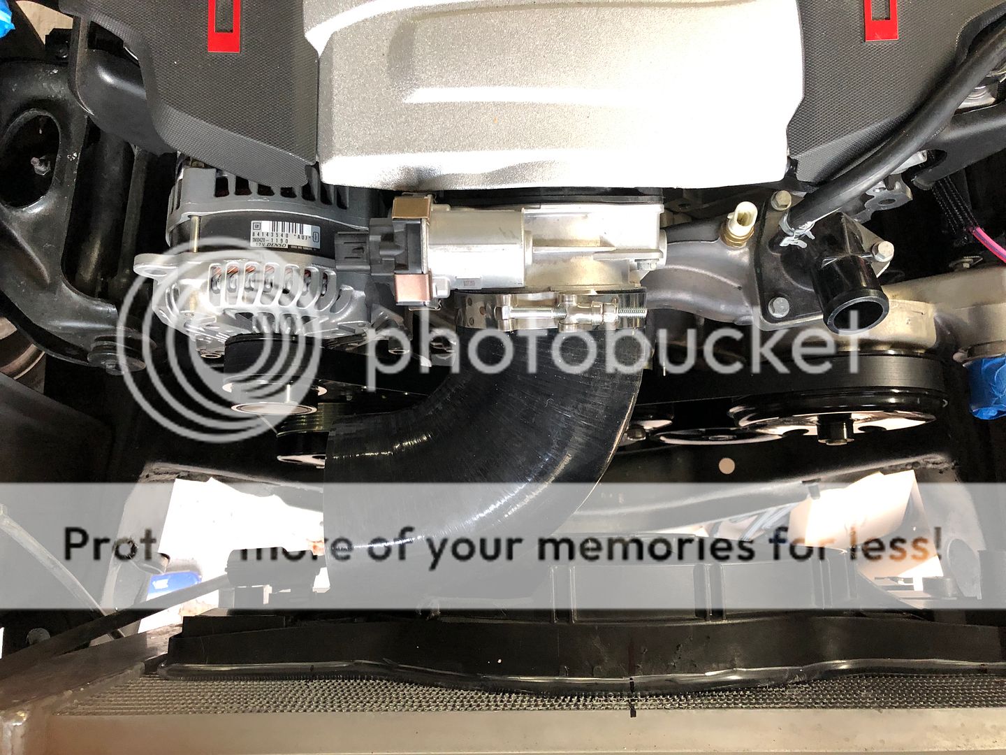
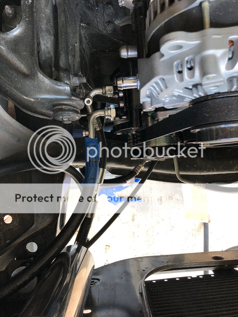
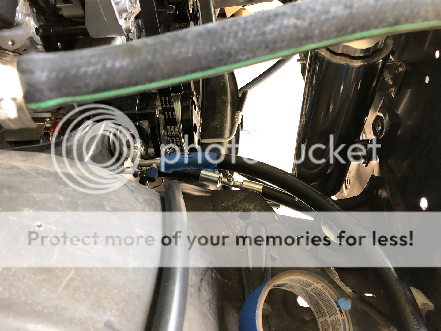
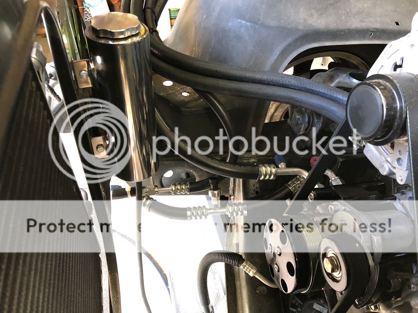
I installed the power steering lines with earls hose and fittings on the high side and some push on barb AN fittings on the low side. I did not purchase enough hp hose so its not as hidden as I'd like but it will work.
Also go the fuel line installed and the low pressure sensor.
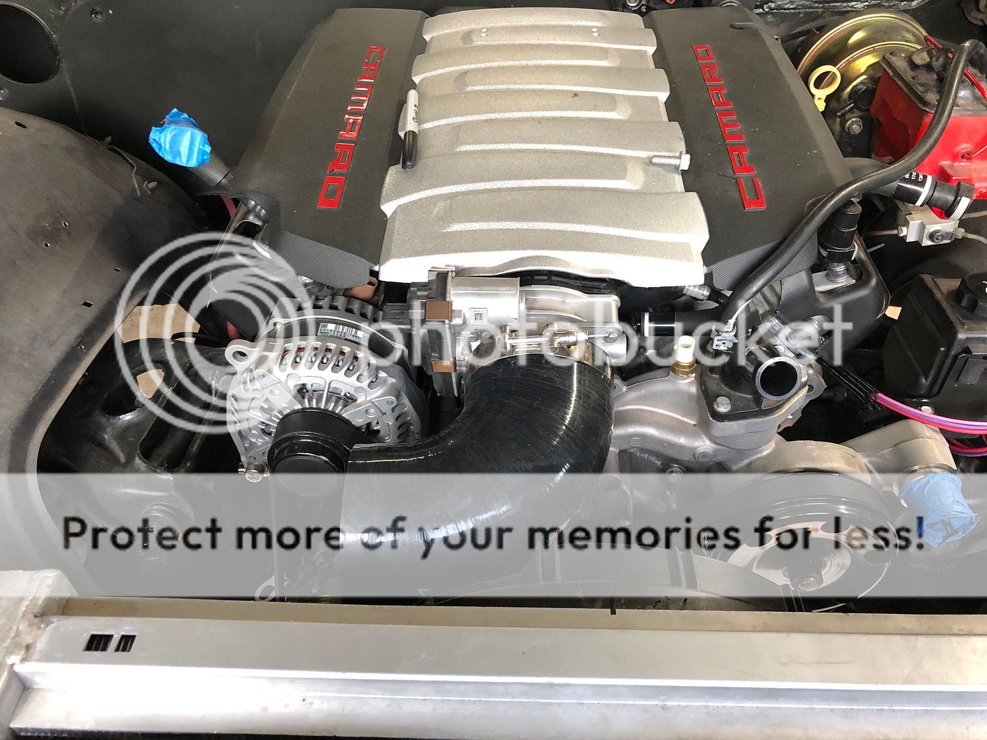
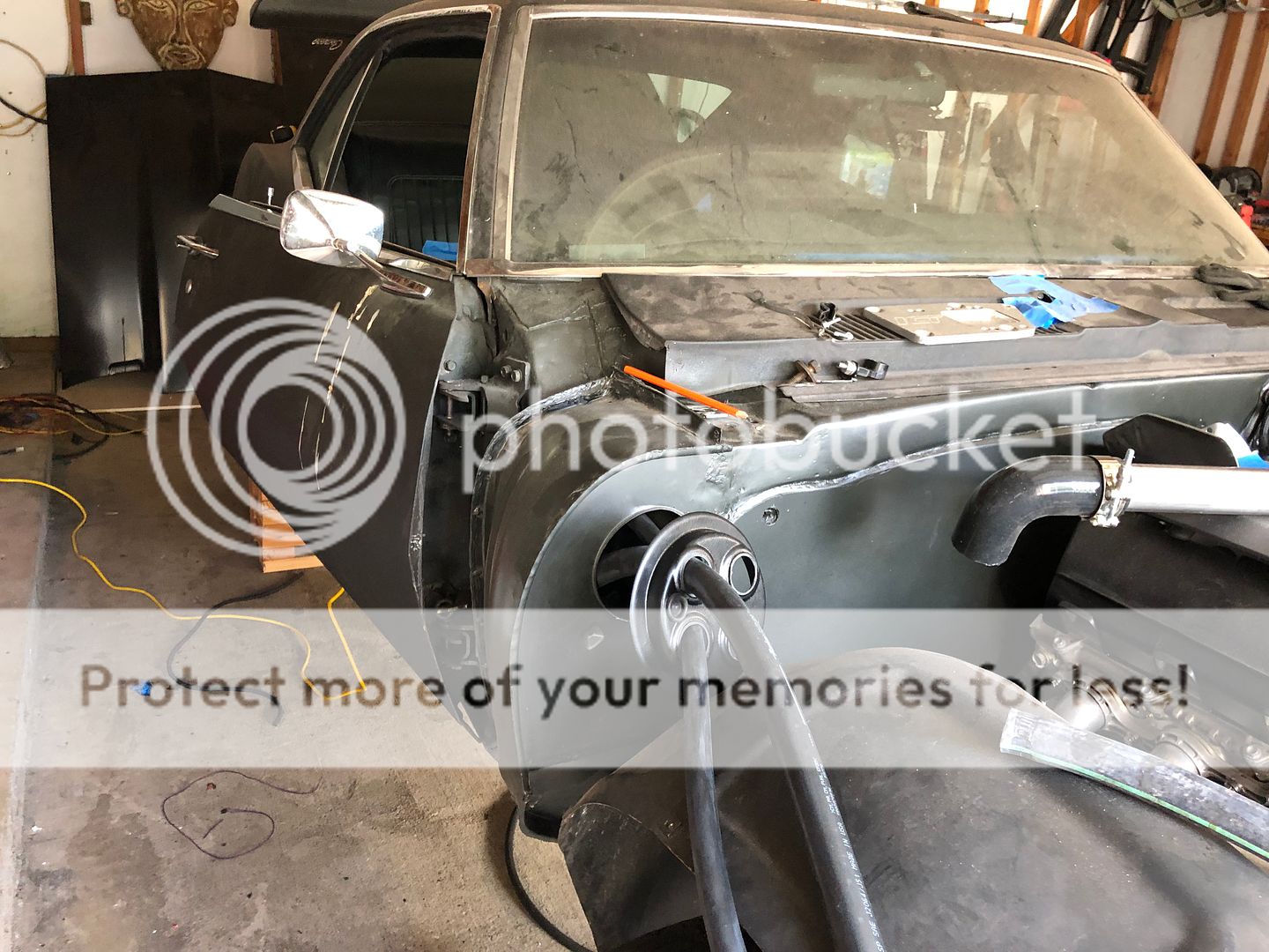
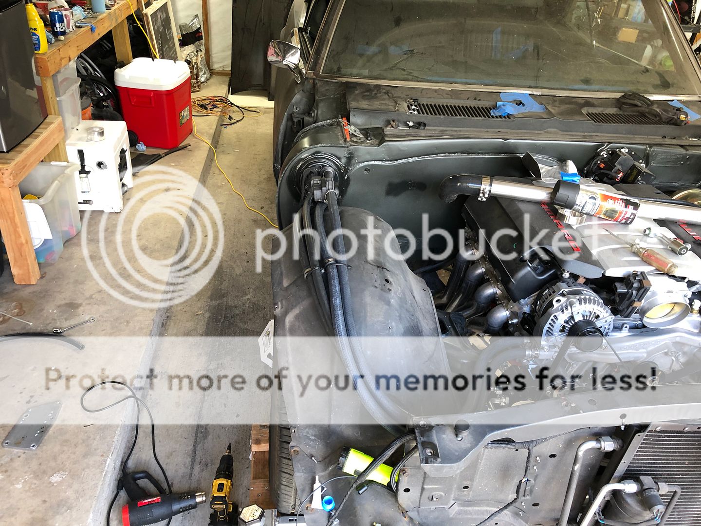
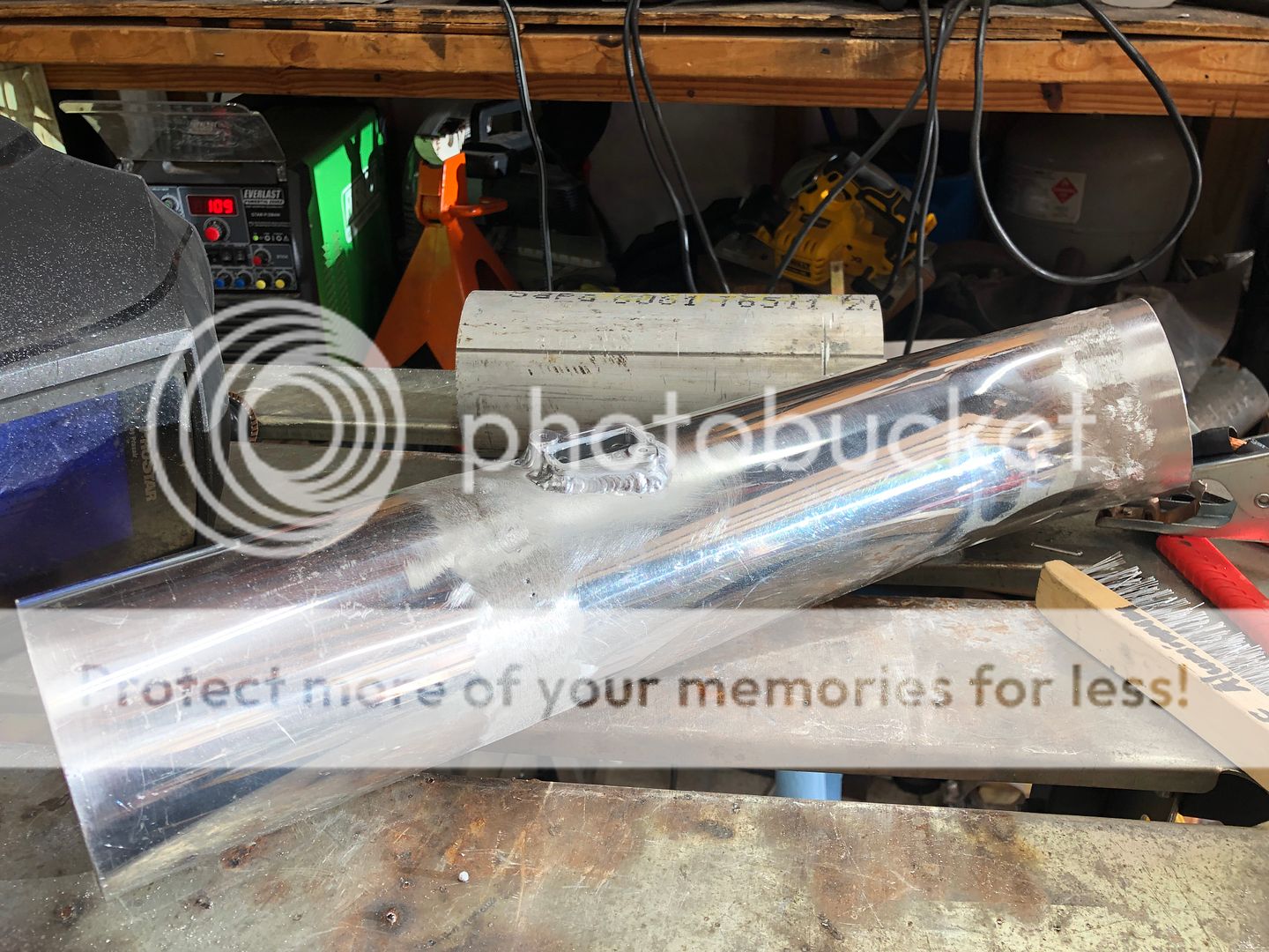
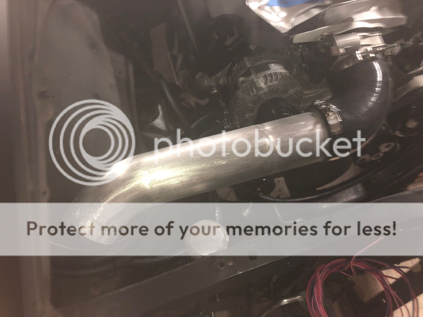
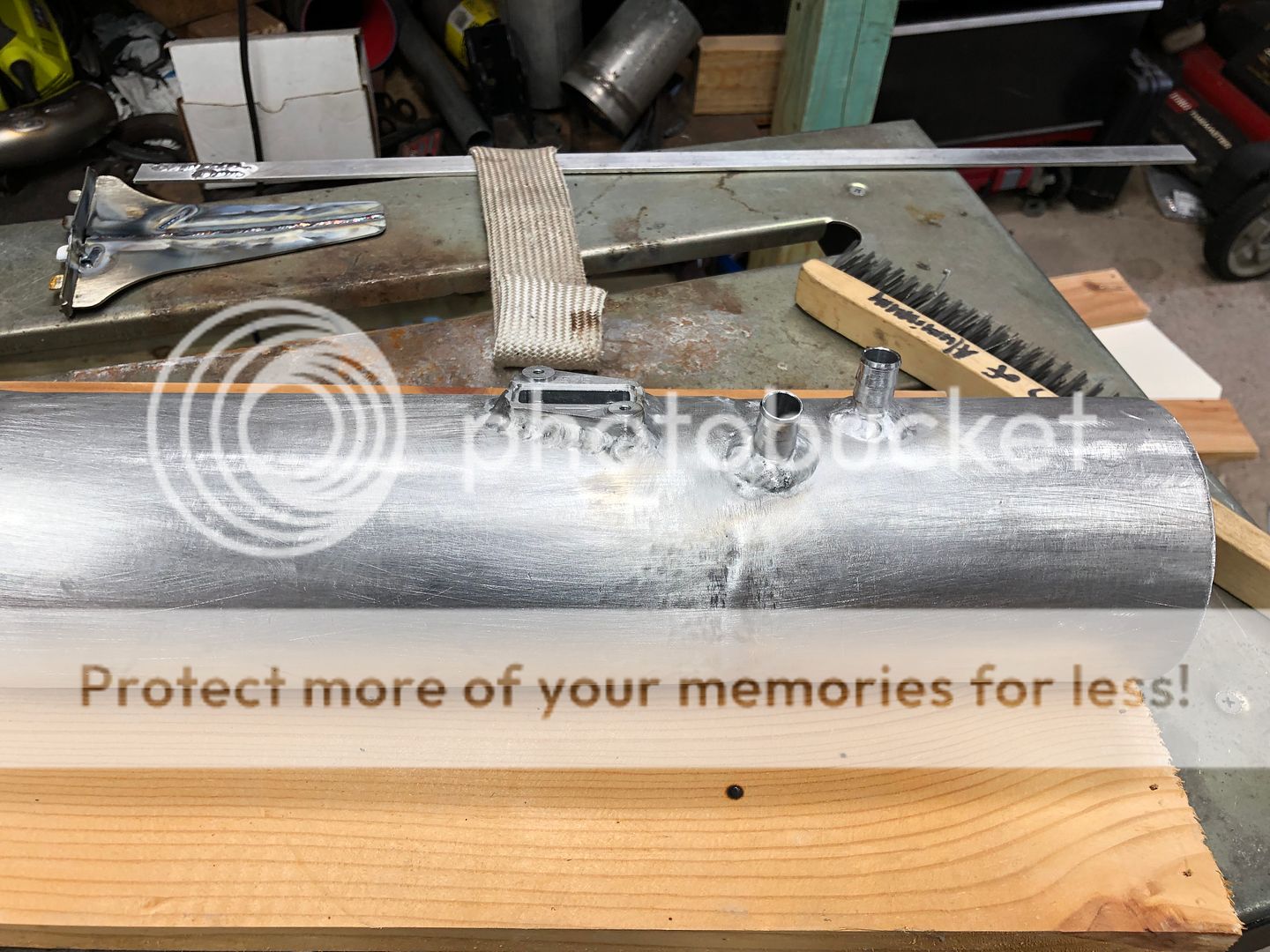
I started building the air intake out of some 4" 90 degree aluminum tubing I had sitting around and cut it to fit. I cant for the life of me figure out what is going on with my welder weather its a gas leak or bad part but I could barley weld this stuff. I had little to no penetration (not a big deal with no boost), ark was all over the place etc... I adjusted the balance in every single position imaginable, cleaned the parts/filler rods to the extreme and no matter what it was not having it. I'm going to figure out whats going on at some point and then install a small bracket on the intake tube to hold brace it on the radiator core support I think. I welded the MAF bung and two 1/2 barbed nipples (not in photo) on the bottom of the intake to hide them. The nipples will vent/pull crank case pressure from the valve covers. I got a filter on the way and I'll get it installed next week.
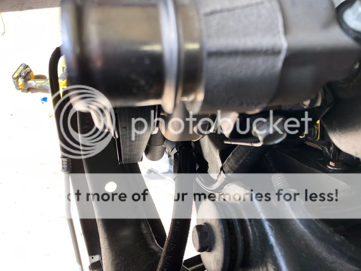
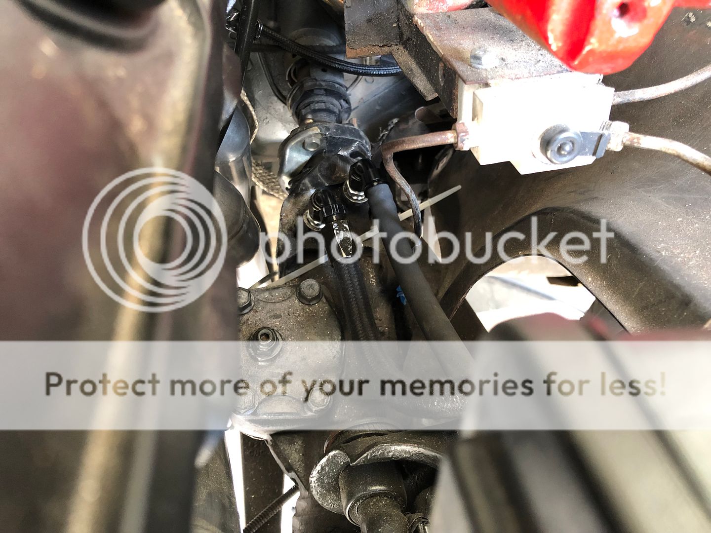
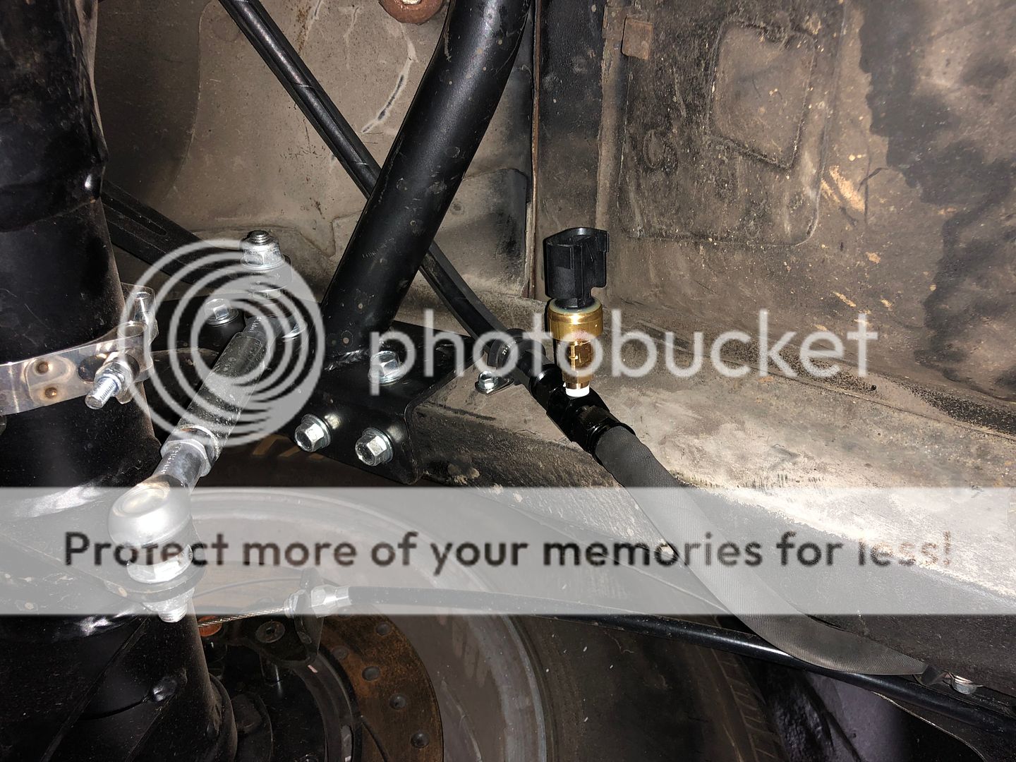

Also go the fuel line installed and the low pressure sensor.
I started building the air intake out of some 4" 90 degree aluminum tubing I had sitting around and cut it to fit. I cant for the life of me figure out what is going on with my welder weather its a gas leak or bad part but I could barley weld this stuff. I had little to no penetration (not a big deal with no boost), ark was all over the place etc... I adjusted the balance in every single position imaginable, cleaned the parts/filler rods to the extreme and no matter what it was not having it. I'm going to figure out whats going on at some point and then install a small bracket on the intake tube to hold brace it on the radiator core support I think. I welded the MAF bung and two 1/2 barbed nipples (not in photo) on the bottom of the intake to hide them. The nipples will vent/pull crank case pressure from the valve covers. I got a filter on the way and I'll get it installed next week.


 07-20-2019, 09:27 PM
#114
TECH Senior Member
iTrader: (7)

Do yourself a favor and and goop up the AC and heater lines where they pass to the inside. You'll get water past the grommets that are supposed to seal those hoses.
Andrew
Andrew
07-20-2019, 10:17 PM
#116
TECH Senior Member
iTrader: (7)
Andrew
07-30-2019, 06:11 PM
#117
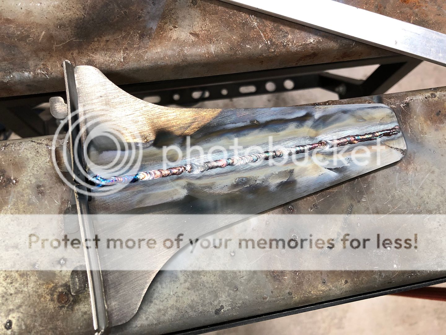
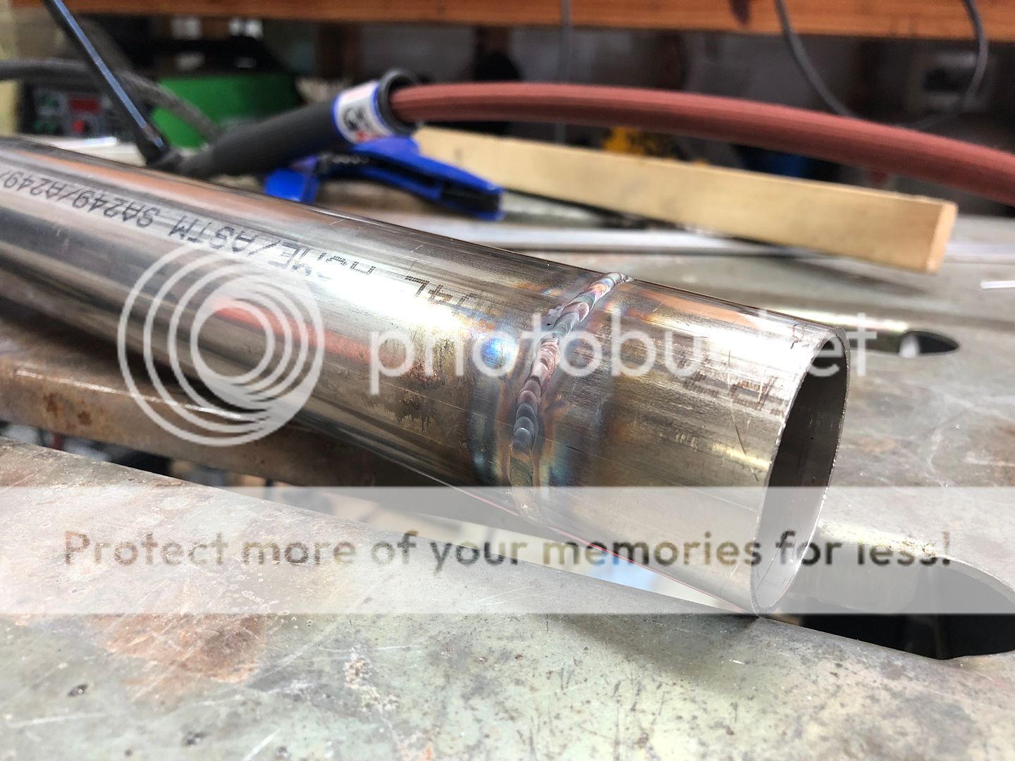
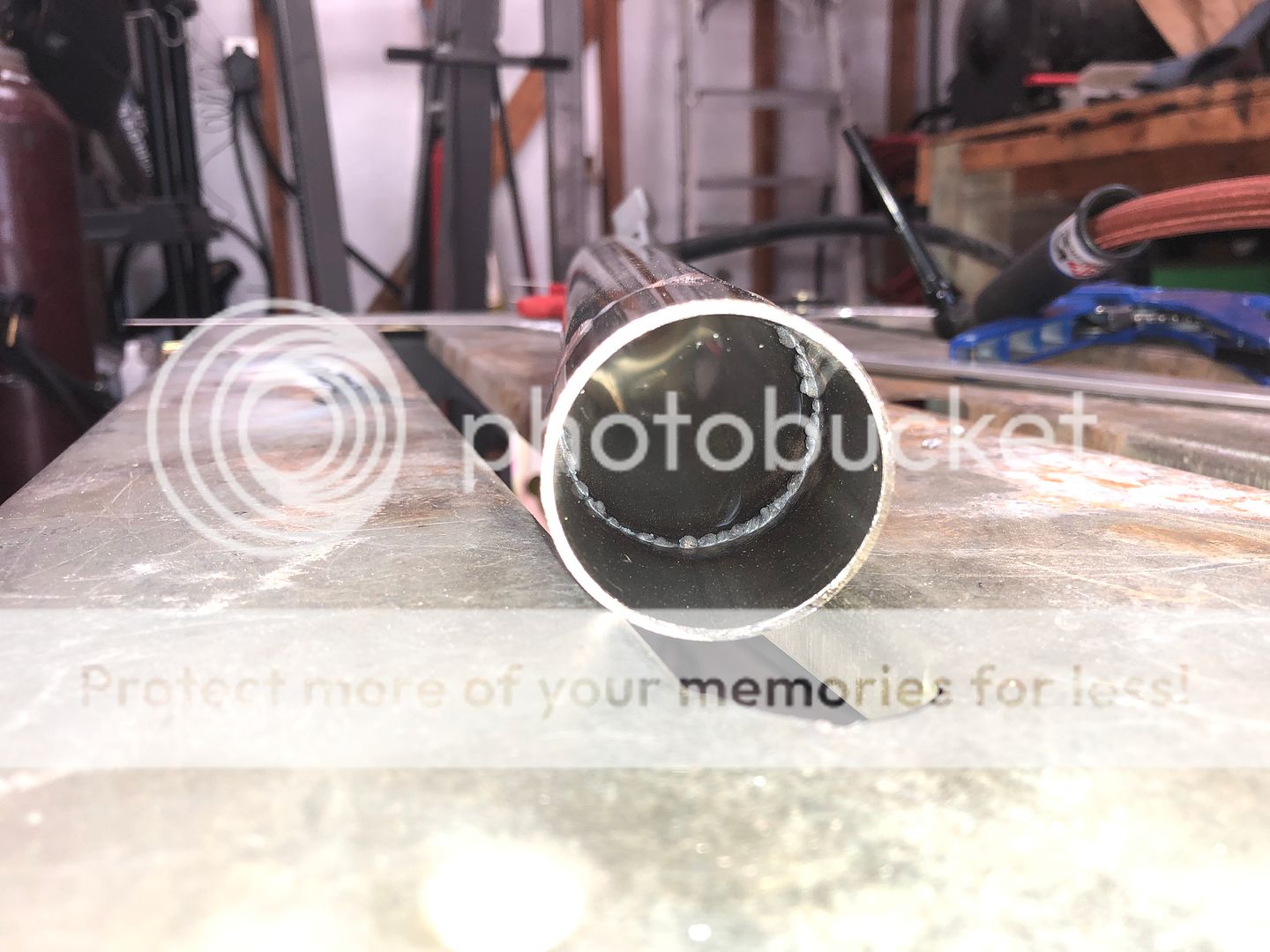
I was able to do a little more troubleshooting on my welding machine. Turns out the flow meter was way off, I purchased an external flow gauge to find out. It requires roughly twice as much air to achive the correct CFH. With running the machine in DC you dont notice it as much but while in AC on aluminum it was horrible. Below is a picture of the 1/2" bungs I welded on the bottom of the intake, they were very rough and I cleaned them up a hair after the machine was operating normal again. Also laid down some SS welds to see if they would be better than before with the correct CFH and they look a little better than before. Did a little practice without a back purge on some 304 tubing to do a little practice for my upcoming exhaust build I'll be doing soon. If you are unaware, you need a purge or flux to protect the back side of the stainless welds from oxygen due to the stainless being reactive while welding, it will look like crap as seen in the photo below.


 07-31-2019, 08:58 PM
#118
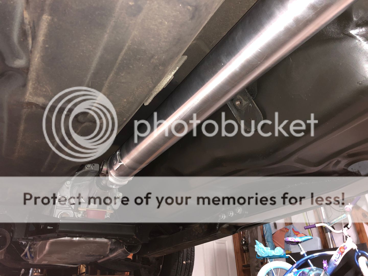
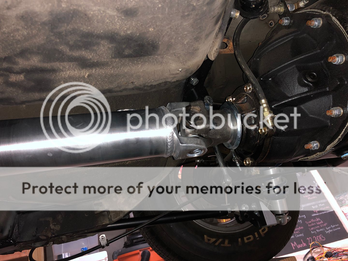
I got a driveshaft ordered from Inland Empire and it looks pretty nice. The customer service was great and they helped me to get the correct yoke for the 10-speed. I had a brain fart though... I ordered the driveshaft with a 1350 series u-joint for my rearend because I was 100% sure thats what I was running. Turns out I had the 1330 series pinion yoke installed. Ended up purchasing a 1350 pinion yoke to solve the problem. Now I have two extra pinion yokes if someone wants one since Curry sent me the incorrect 1310 yoke initially and now I have the extra 1330 yoke.
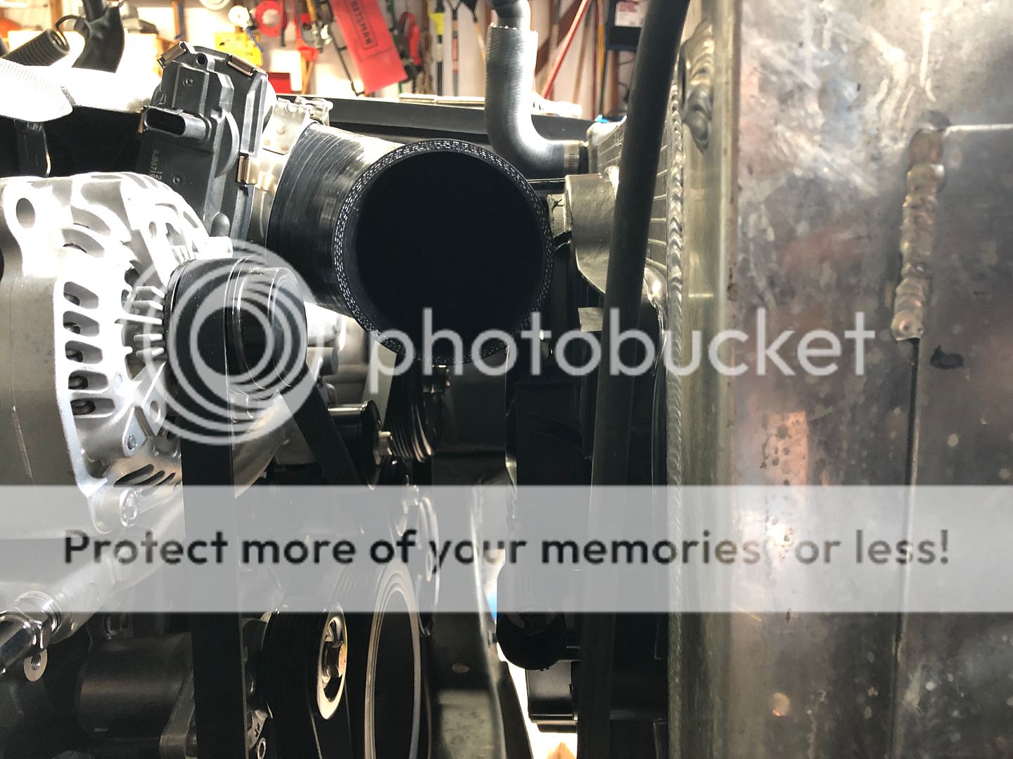
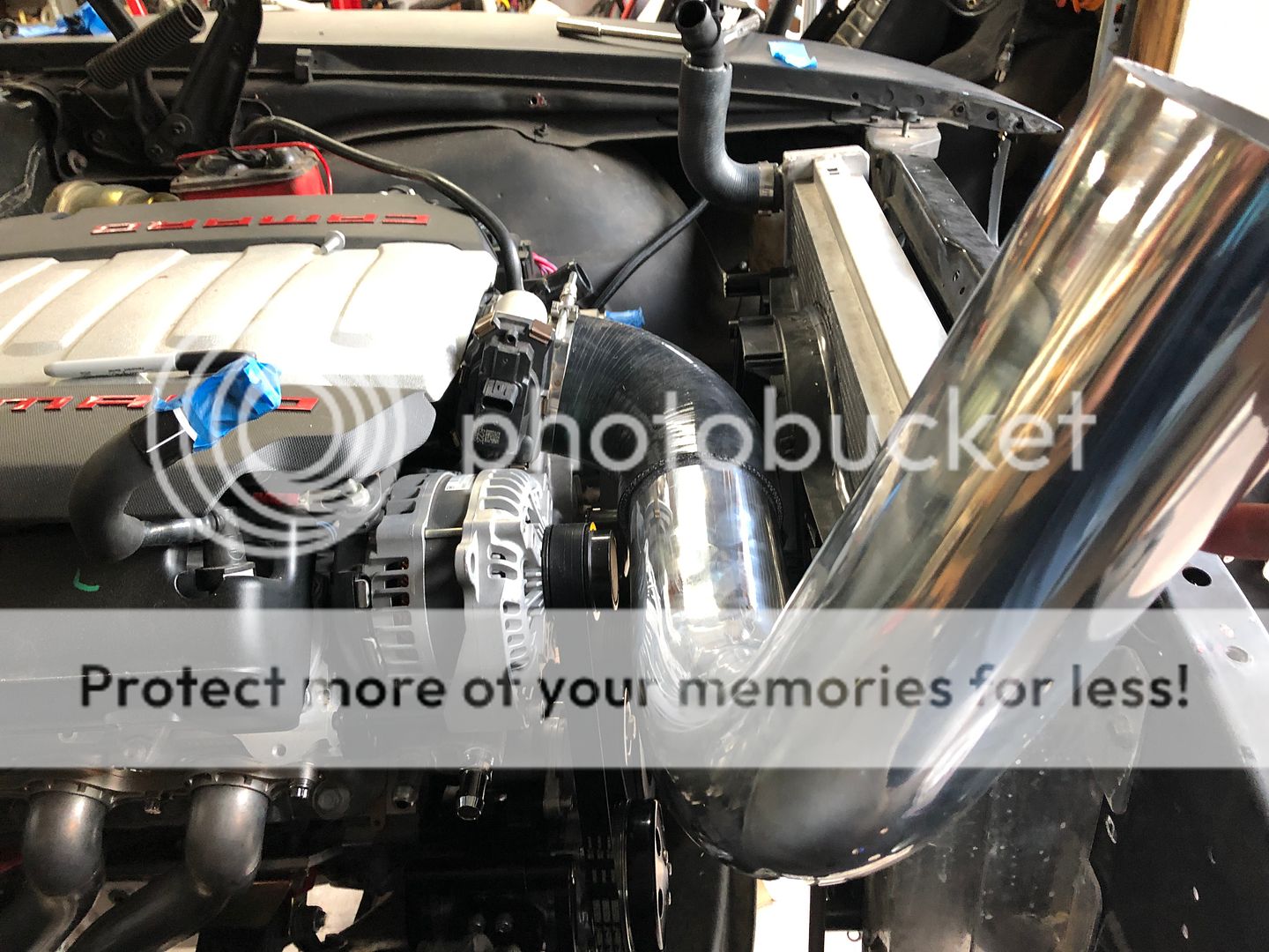
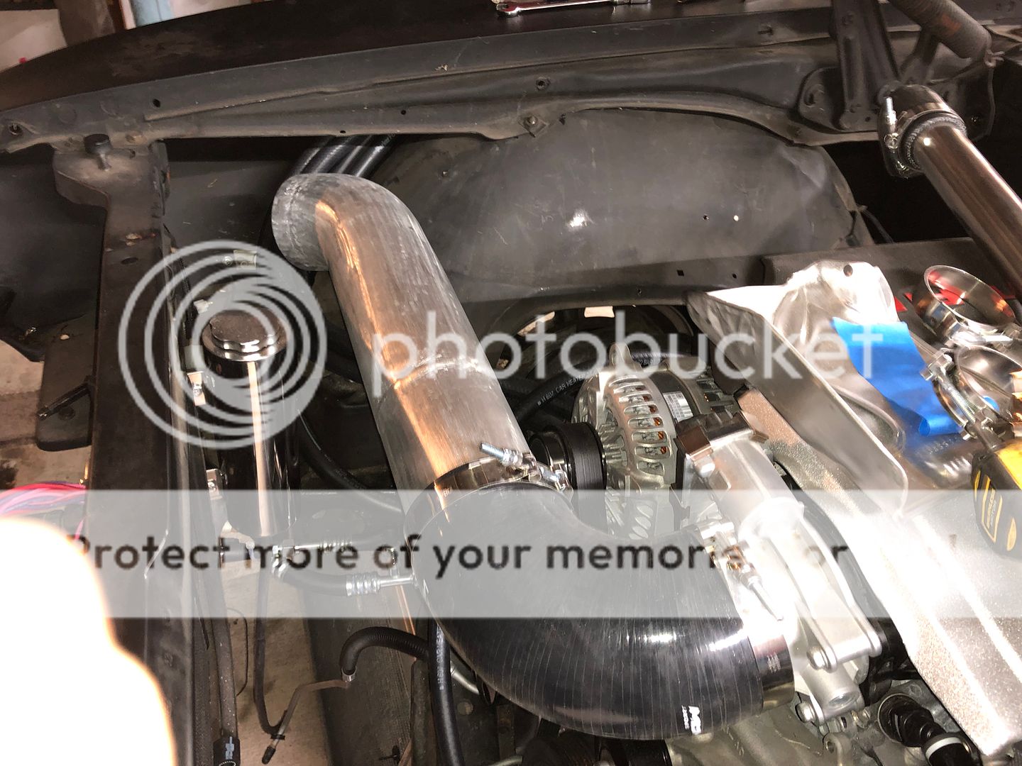
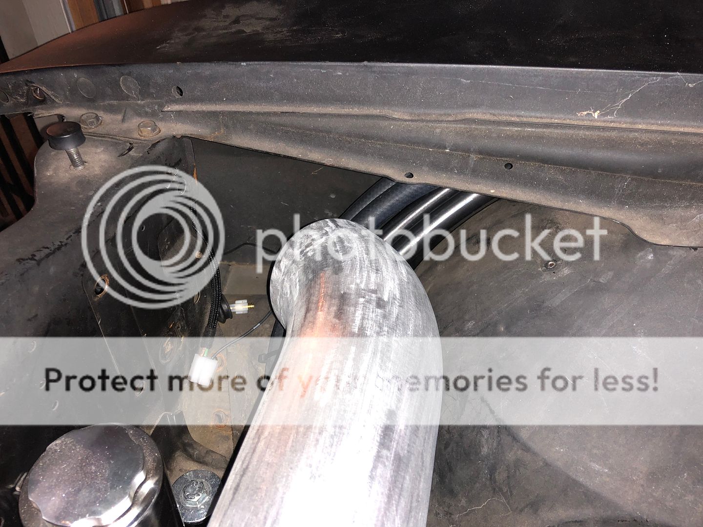
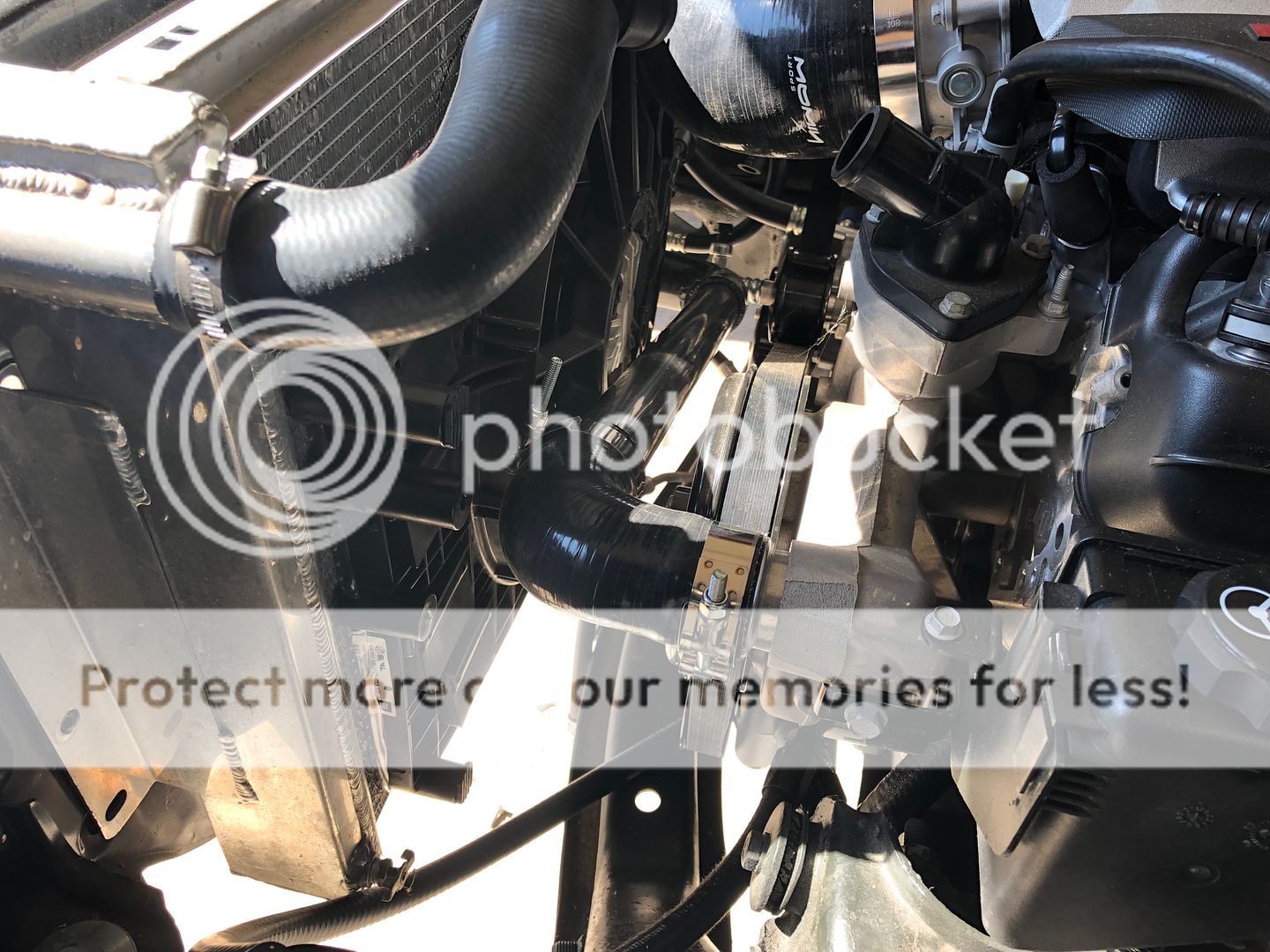
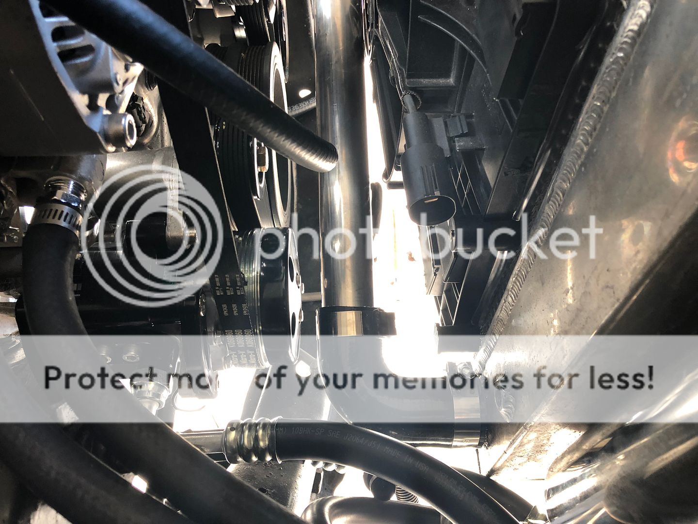
I was able to install the lower radiator hose too, I just used some 1.75" SS tubing and silicone elbows to connect it. I'll be working on the upper hose in the next few weeks. What I have now does not look very appealing so I'll use more SS tubing to match the lower section.
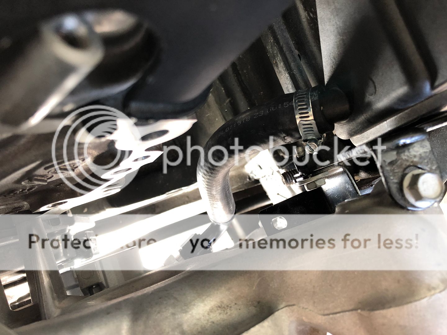
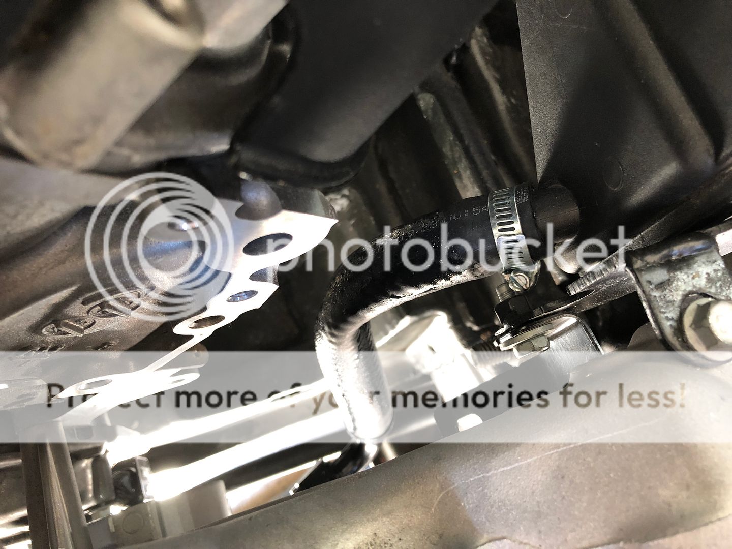
I'm always learning and I have never really made custom lines for power steering so this was a learning experience. Turns out that you cannot use leftover 5/8" heater hose for the power steering reservoir feed hose. The hose looks like it is sweating fluid out of it, the fluid just ate its way through the hose. I purchased some actual PS hose and swapped it out. This had me question the return line coming off the steering box to the reservoir. This was also leftover hose from the fuel system and from what I was reading fuel hose cannot be used either. I contacted the manufacture of the hose and they said it will be fine as long as its on the lower pressure side as the hose is rated for PS fluid.
I was able to install the lower radiator hose too, I just used some 1.75" SS tubing and silicone elbows to connect it. I'll be working on the upper hose in the next few weeks. What I have now does not look very appealing so I'll use more SS tubing to match the lower section.
I'm always learning and I have never really made custom lines for power steering so this was a learning experience. Turns out that you cannot use leftover 5/8" heater hose for the power steering reservoir feed hose. The hose looks like it is sweating fluid out of it, the fluid just ate its way through the hose. I purchased some actual PS hose and swapped it out. This had me question the return line coming off the steering box to the reservoir. This was also leftover hose from the fuel system and from what I was reading fuel hose cannot be used either. I contacted the manufacture of the hose and they said it will be fine as long as its on the lower pressure side as the hose is rated for PS fluid.


 08-01-2019, 04:12 AM
#119

Man, I bet you are getting really excited. It won�t be long now