When you click on links to various merchants on this site and make a purchase, this can result in this site earning a commission. Affiliate programs and affiliations include, but are not limited to, the eBay Partner Network.
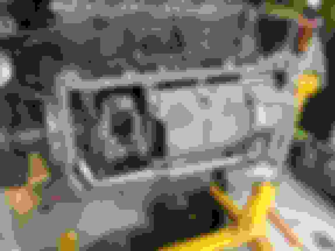
I then proceeded to take off the flywheel and the modified truck oil pan. I was a little mystified (pun intended) why there was so much oily grime on the inside of the bellhousing.. the clutch slave looked minty clean, and the backside of the flywheel was clean. Well one of the 6 flywheel bolts allowed a dribble of oil past when I removed it, which was weird. Then I yanked the flywheel off and turns out there's a nice pool of oil at the bottom of the rear main seal.. sweet.
Good thing to catch now, while everything is out and apart. I know I replaced the front main seal when I rebuilt the engine, but I don't particularly remember replacing the rear main seal, not to mention when I poked at the seal and deformed it, the seal liked to stay deformed and not spring back. So, now have to try and find a rear main seal before next weekend. Essentially that stopped me from final-installing the new Holley oil pan, new flywheel and new clutch, as well as the transmission today (if we're getting real optimistic).
I pressed on, and started the new Holley pan install to see if there'd be any hiccups. The Holley instructions are exceptionally good, and provided detailed schematics of a bunch of things including where to trim the full-length (truck, etc) windage tray to fit their pan.
The pickup tube was close to the windage tray, but didn't need any clearancing, which was nice.
I'm not sure about other engines, but my original truck pickup tube mount flange was only one-bolt at the oil pump, which I never liked. When removing the truck oil pickup tube, I noticed the o-ring and tube where floppy as hell inside the pump the instant I cracked the single retaining bolt loose.. so I'm hoping maybe that was an area of introducing the slightest bit of air and thus slightly lower oil pressure, once up to operating temps.
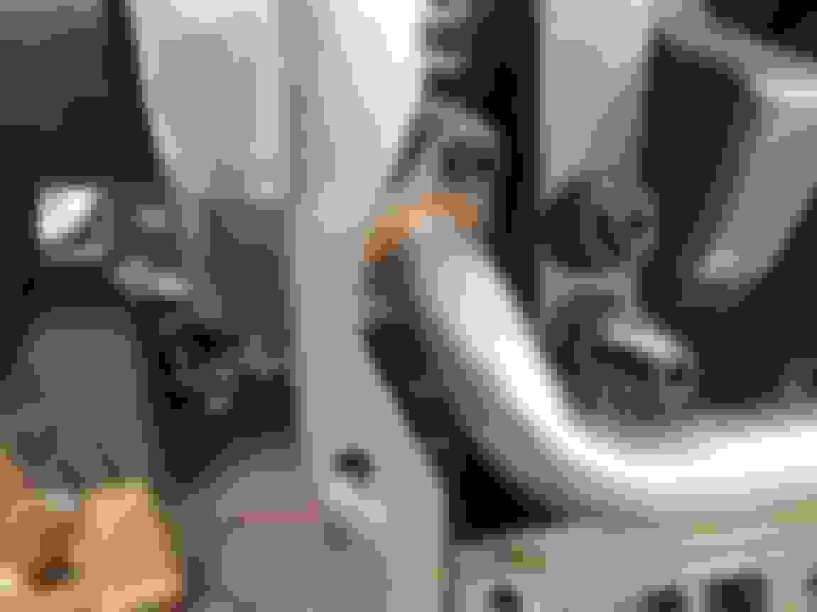
Either way, the Holley pickup tube and supplied GM o-ring was a VERY snug fit to the oil pump, which I liked. The Holley instructions say to install the pickup tube entirely into the oil pump before using the two retaining bolts to final tighten it down. Well the o-ring was such a tight fit (even with fresh oil on pickup tube, o-ring, and oil pump) that I could only push the pickup tube maybe 80% into the oil pump. The o-ring was probably 2mm past being visible on the pump, so I'm quite certain that the o-ring migrated past the lead-in chamfer on the oil pump, and isn't pinched. In fact I did an oiled test-fit first before final install and the o-ring wasn't pinched at all... it was just a tighter fit than described in the instructions.. but I'll take it.
I'm also a HUGE fan of the two-bolt securing flange on the pickup tube at the pump, complete with brazing for rigidity.. I have a good feeling about the security and sealing of the tube in the pump...
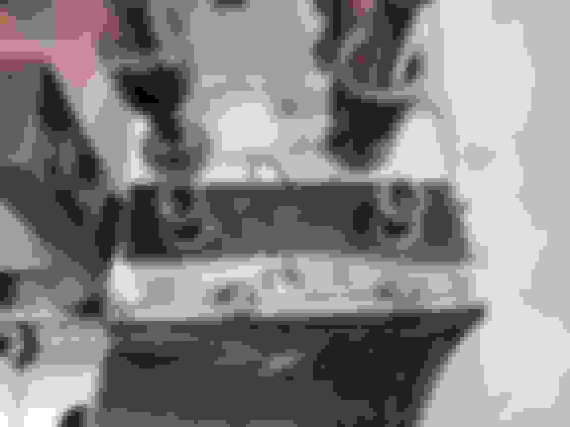
The pan installed nicely, only mocked in there until I re-seal the rear main cover.
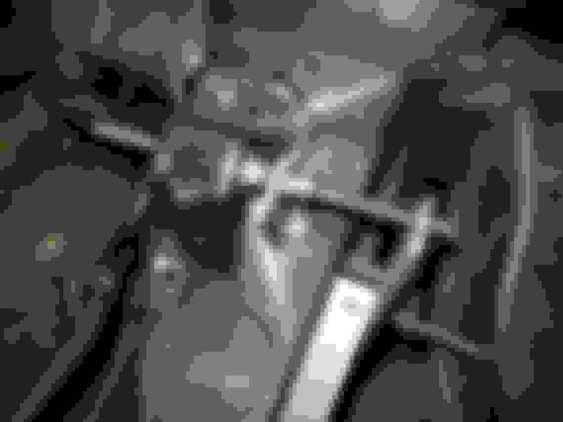
If Toddoky is following along, this may be useful to him... the new Holley pan came with 2 X M6x30 flange head hex cap screws for the standard GM F-body oil cooler bypass plate above the oil filter. Unfortunately the flange OD on these screws is too large to fit inside the counter-bore on the Earl's oil cooler CNC'd adapter I'm using. I measured the thickness of the oil cooler adapter where the M6 screws pass thru as 10mm, and the maximum thread depth on the Holley pan for these M6 screws was 20.5mm. So even if the Earl's adapter was counter-bored with a larger diameter to share the 30mm long flange head cap screws, with production tolerances they might bottom out in the pan before fully tightening the adapter down.
The other thing, which I think is the real issue, is that the Earl's adapter doesn't come with any mounting screws, which is a bit disappointing. I work with metric M5/M6/M8 fasteners every day, so supply of socket head screws isn't an issue for me.. but I have a feeling this may be an issue for some people in various parts of the states. So I ended up cutting down some M6 socket head screws to 25mm UHL to provide 15mm of thread engagement, which is 2.5x the thread diameter, which should be plenty...
Looking good Joe. WHats the reasoning behind not going with the thermostat cooler pc. instead? Are you going to run the EARLS cooler too? I don't recall the engine specs, stroker?
That valve stem defect is bogus. That'd tear up a seal in no time not to mention a defect like that could lead to complete failure / dropped valve. Good job inspecting parts.
I like that the oil pump pickup has mounts on either side of the windage tray. My Autokraft pickup is hanging in the wind from just one side. I had to adjust the pan clearance a little. Did you check your pickup clearance? post #640 in my thread shows how I measured and adjusted the clearance on mine. Also post #614 has a blurb on installing the rear seal. *EDIT* What kind of oil control does that pan have around the pickup? I am not sure how effective they are, but my Autokraft pan has some trap doors and extra baffling around the sump to keep oil at the pickup.
I hope you have space for those two fittings coming out of the pan just under the motor mount area. With my engine location (1/2" setback) those would either be interfering with the frame stands or just barely behind them. Are you confident those will have sufficient clearance? Do you have some backup options for fittings (90+90 maybe?) in case they don't clear? Or can you mock the motor mounts and stands onto the block to get an idea of where those will end up?
Last edited by -TheBandit-; 04-09-2018 at 10:34 AM.
Yeah, I'm following along. I'm going to wait until you get everything wrapped-up and reinstalled in your car before cherry picking information out of your report that I will want to forward to other design team members to review/evaluate.
Jimbo.. I was originally going to use a thermostat-controlled oil cooler adapter.. I'm not quite sure what the exact reasoning was for not getting one. I think I figured that oil is going to heat up so quickly anyways, plus possible restriction in the thermostat valve.
I did really like the idea of having all the oil cooler lines blocked off such that on startup, all that oil goes immediately into the engine bearings and there isn't any delay in oil supply by having to fill all the oil lines pre/post-oil cooler. Thinking about it, I'm unsure how long the thermostat would stay open after shut down due to the oil temp, and thus how much drain back to the pan might be allowed due to warm oil after shutdown.
Now that I'm thinking about it, I'll try this setup and see how quickly my start-up oil pressure builds and if an "open" adapter and the oil line drainback is an issue. Luckily the adapter is in a real easy place to swap out if needed.
Clint... I agree with your points about the dual-bolt oil pickup tab. I'm shocked at how wobbly my truck pickup was literally as soon as the single bolt was loosened. I didn't bother to jiggle the pickup tube with the bolt tight, but I can only imagine that the o-ring wasn't a perfect seal. That o-ring was I think my 3rd attempt, and was a brand new GM unit that I installed verycarefully with plenty of oil to not pinch it.. oh well that's old news now.
I know what you mean about the pan turbo drain fittings looking crazy far forward, however I did measure the longitudinal location on my truck pan when the engine was still in the car, and it appeared there would be room to spare for fittings and a wrench... we'll see!
Toddoky... Sounds good. I'm just a dude that does garage wrenching, but I have accumulated quite a bit of design/QC experience at work... so if you have any specific questions, feel free to ask away.
A new LS9 exhaust valve was just delivered, as well as some ARP fastener lube and a couple other misc things, so tomorrow should be rear cover install, oil pan final install, 317 head removal, and LS9 head mockup install. I'll mockup install the LS9 heads with the used LS9 gaskets in place, to confirm that the pushrod length hasn't changed from previous 7.400", as well as be certain that there is no valve interference.. however I have -11cc dished Wiseco pistons so I have no reason to believe the valve will be remotely close to the pistons.
I got the rear main seal locally (discovered it was leaky AFTER I already ordered just the exhaust valve.. go figure... didn't want to pay multiple shippings) and installed on the rear cover. New seal has noticeably more elasticity, and is now a reverse lip seal vs the old seal I had, which I'm pretty positive was the one original to this 2005 LQ4 motor.
Got the modifications to the transmission cross-member wrapped up. Slotted the passenger side mounting tab to compensate for the shrinkage that occured from welding. Once fully welded, the whole thing was very *slightly* bendy when I put all my weight onto it on the bench, so I decided to add some reinforcements to the clearance notches so to be extra beefy. They existing notches are 1/4" thick, and I added 1/8"x1" strips on the tension (under) side once the trans weight is on it, and the center of the x-member wants to flex down, AKA spread open the notches. Before/after bending was definitely improved just on the bench, and once it's installed an the mounting bolts are tight (preventing the overall width of the thing from enlarging once it flexes) it should be totally fine.
I picked up the replacement for the gouged exhaust valve today... not! I got a delivery notification that the replacement valve had arrived and went to pick it up and guess what, I got nothing but a 12"x18" cardboard box filled with nothing but a single piece of brown wrapping paper and a plastic tray that looks like it is what's used to hold an order-in-progress at a warehouse... frustrating!! An angry phone call will be going out Monday morning..
Then I got the Holley oil pan and re-sealed rear main cover installed, which was smooth sailing... aligned to rear bellhousing mounting face and all...
So this is something that I've realized since the start of making the driver side downpipe, but maybe haven't shared... the driver side engine mount needs to move forward for both mount life (heat) as well as plain old clearance for the downpipe to the subframe-side motor mount bracket.
This is what the downpipe clearance would look like if I didn't ovalize the 3" downpipe...
Here's what the mount normally looks like (the short-and-wide SBC motor mount shares the middle-top mount hole with the forward/upper LS block mount hole...
Here's the new setup, I moved the motor mount 1.75" forward, which is the same offset between the middle-top mount hole and the bottom right mount hole. I used 1/4" L-bracket instead of plate just to introduce some rigidity into the plate instead of just using flat stock, since the plate has the majority of motor mount hanging in front of the forward block mounts, instead of half in front of the block mounts...
I had to clearance the backside of the L-plate in these two areas to clear a boss as well as a rib on the block...
This meant I also needed to move the solid subframe-side motor mount bracket 1.75" forward. I used some 7/16" all-thread to align the mount hole, and made a 1.75" long aluminum tube spacer to flip on either side of the solid mount bracket for before/after cutting....
I really like how the transmission crossmember turned out - slick!
Considering the lack of access underneath to bolt those frame stands down, I might consider just fabbing some replacements from plate that bolt in the same location as the originals. Or cut the feet off the originals and weld them to a plate mounted in the original location.
Also the engineer in me squirms whenever I see upside-down engine mounts. Do you have sufficient clearance in front of them for the accessory drive?
Hi Clint, my plan was after some measurements, to cut the feet off and weld on thicker plate that reuses the stock hole locations on the subframe. Then I plan to make a 1/4" thick two-hole plate washer for the upper two holes, to use on the backside of the subframe where the nuts would be, to help spread the load across the subframe metal.
No accessory drive issues... in front of that motor mount area there is only the power steering pump, the backside of which is ~1" in front of the front face of the block.
Update on the driver side subframe motor mount, relocated the mount itself 1.75" forward on some 1/4" plate that utilizes the stock hole locations on the subframe. Added some L plate to round off the mount base, as well as added a couple gussets for good measure....
Got the driver side motor mount installed, and test-fit the engine to see what oil pan and turbo drain line clearances would be like...
This shows the passenger side turbo oil drain fitting lining up almost dead-on with my factory (un-moved) subframe-side motor mounts... more info on that in the next post..

 04-08-2018, 11:51 PM