When you click on links to various merchants on this site and make a purchase, this can result in this site earning a commission. Affiliate programs and affiliations include, but are not limited to, the eBay Partner Network.
Haha I don't have a hope in hell of finishing it in June... July is going to be a stretch too... next two, possibly three weekends I'm away. Plus it's a whole new setup that will need a lot of tuning before I even think of trying to run it hard in a competition or track/auto-x event. Although I do appreciate you doing the legwork for me haha.
Regarding the straps, I do know what you mean about the point load of the crush sleeve on the rubber and possibly tearing the rubber from this. However I undersized the sleeve length so that once the bolt+washers+nut is tightened on the rubber it does pinch the rubber a significant amount... enough that I have a really hard time rotating the rubber about a single bolt/sleeve assembly. I really do prefer the crush sleeve idea since it allows a predetermined preload of the rubber onto the bolt washers, but also provides a positive hard stop to tighten the **** out of the bolts... I really don't want nuts loosening off from only being "tightened" against a pliable rubber that felt tight initially, but then smooshed out over time and the nut/bolt loosened off.
We are made from the same stuff Joe. I don't know anyone else that would post a dozen photos and debate the merits of how to punch holes in rubber to hang mufflers. Wish you were closer. And I like what you did with keeping some crush on the rubber - it's going to work just fine.
I'll keep posting on events. You gotta get the car on a course by the end of the year. I don't care if you baby it the whole way... I don't care if you drive Sally instead of Roxie. If you don't like it I'll leave you alone but I have a feeling you would get a kick out of it.
Hahaha.... if you're not over-engineering something then you're under-engineering it, right?? I over think everything.. sometimes it becomes a burden.
This is the kind of small-detail stuff that Mark and I shoot the **** about, unfortunately we don't hang out as much these days. But between the 3 of us I'm sure we could engineer up some ridiculous contraptions!
I know I know.. I really do want to test it out to the limits on a track, but knowing me I won't want to take it to test out knowing it's not within a close % of what it eventually could be. I certainly wouldn't want to waste my time & money just to half-*** putt-putt it around a course to say I've done it... I'd rather use that weekend time wrenching away on it to get it closer to a more finished and dialed form.
It sounds like you're in the trap of feeling like you or the car are "not ready". The reality is neither are EVER ready. I did my first autocross in 2009 on bone stock suspension with my small block smoking oil and crappy tires. Lap times were WAY behind the competition, but I HAD FUN and I learned a ton. Last time I went I had good front suspension and engine, but still old crappy tires and a completely mismatched rear suspension. This time the car is light years better, but I am too because of the experience... even still it's not "done" and I'm a seconds behind experienced folks driving similarly setup cars.
When I say "put around" I don't mean Sunday driving - I mean driving a little bit conservative and accepting the fact that you will not be the fastest guy out there and there are still things to make better on the car. If you set your expectations too high, you may never get on the course. Plus going out there with it partially done will help highlight what the real needs/wants are to go faster. Your car has a lot of the goodies to be quick - plenty of tire, good suspension, and insane power. If you get it to the point you feel comfortable/safe driving it down the road, the car is ready to take to autocross. Forget about it being finished or dialed in. Shake it down, yes, but don't hold off on going just because it's not ideal.
I totally know what you mean... trust me I'm not one to hold off until something is 100% ideal, I've beaten real hard on some very questionable setups in the past. What I meant by "not ready" is in fact some huge basic driveablility concerns such as:
- need to idle tune, part throttle tune, WOT tune for fuel table
- need to part-throttle tune and WOT tune boost control curves for gears 2-4
- need to make sure new cooling system is adequate for normal driving and "spirited" driving
- need to replace front right wheel bearing
- need to rebuild tilt steering column bearings (lots of wobble for the last couple years)
- need to make front sway bar (not necessary to "drive" it.. but I've spent enough years driving without one to know it would help a great deal)
This is of course after all the work I need to do before I even fire and give it a first test drive, such as:
- fabricate core support to have radiator mounts and intercooler mounts
- complete intercooler upper tank and piping to throttlebody
- make charge piping from turbos to intercooler
- buy, locate, and fabricate oil cooler, and route lines
- install, plumb, and wire trans fluid pump
- make air filter to turbo piping and supports
- extend wiring for MAP, add wiring for 4+ new sensors
- route turbo feed and drain oil lines
- fully weld remainder of the exhaust tubing
- route valvecover breathe tank lines
Granted this list of stuff left to do is drastically smaller than it was even a month ago.....but my hesitation to commit to any June (hah!), July (maaaaybe), or August (more likely) track times is simply because I still have a fair amount of stuff to finish before I even drive it for the first time.. and I don't want to take it to the track after only "several street shakedown drives" when things sure as **** won't be close to dialed or even halfway-tuned. And I can already count 4 weekends between now and mid-July that I'm out of town!
I love how short the lists are getting! I think some of those issues in the first list could be worth overlooking, but I understand why you'd want to address them. Once you get it close to running and driveable again you can take a decision when to do an event. I'll try not to bug you about it any more until then.
Got the exhaust hangers and brackets wrapped up yesterday (just tacked in place). The dual pipes are bolted to each other in two places (front & back) to keep the entire exhaust as a solid unit, to help give the rubber straps and easier job with less independent deflection..
Next up, I FINALLY found a belt length that will work well with my setup.. 104.5" long. It's hard because I was finding inconsistencies between different manufacturers' "effective" and "outside" and general belt lengths, which led to me just getting a couple to trail and error test in real life despite my best efforts to estimate length in 3D on the computer.
It's easy to install around all the pullies, and the belt lands it right at the correct mark on the tensioner. With the rad+fans installed there should still be around 1.5" room to stick a hand in there and re-route things if there needs to be a roadside fix.
Finally getting around to radiator stuff too... this is going to be tight!
The C&R radiator I'm using comes with a straight-thread fitting at the top of the radiator, which is annoying since it's sold separately but also nice since it's less welding needed to be done on the radiator. Naturally I need to hack it up to fit my needs...
This is the reason why.. if I left the fitting as a straight nipple with a rubber 90* on it, it would rub the passenger side compressor housing...
The lower fitting also aims it directly at the subframe, so off that has to come too....
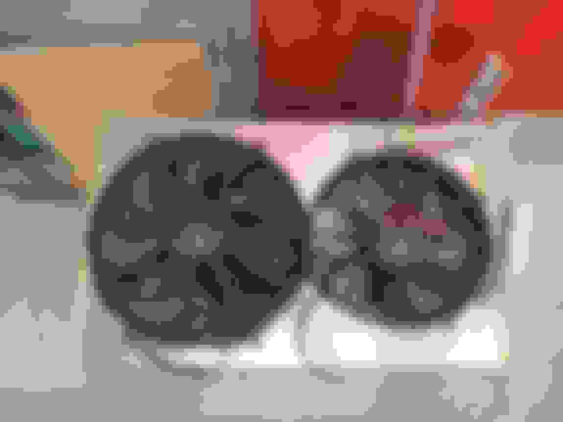
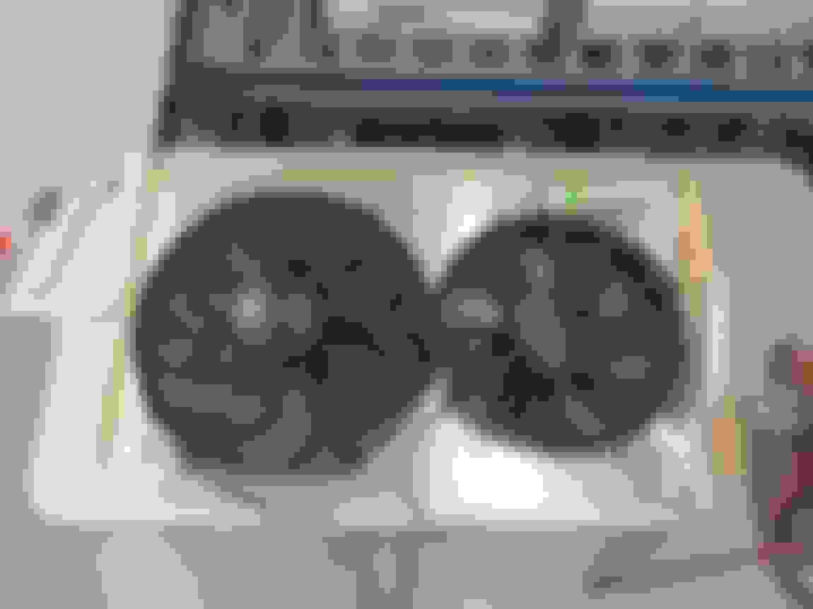
Fan combo I'm going to run.. ~2000cfm 25.4A 16" Derale/Spal fan (P/N 16136), combined with a ~2000cfm 24.8A 12" Derale/Spal fan (P/N 16924)...
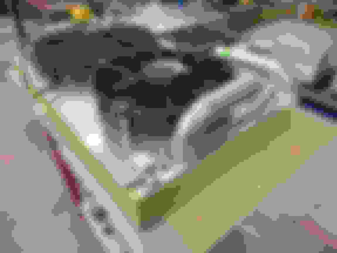
Clearance is tight on the driver side too, but should work. No idea where I'm going to jam the coolant overflow tank... probably on under the driver side turbo compressor housing, on the core support
Intercooler mockup. The intercooler top tank is really the last big fabrication box I need to check off...
Juuuuuust barely fits behind the grill....
Just need to figure out how to merge this elbow to the top tank geometry...
I'll be impressed if that second fan ever turns on outside of track work - mine has intermittently kicked into high only in temps in the low 40�s (~110+�F) with my AC on max. And I learned in the process that factory high-speed fans aren't commanded on until ~110�C/230�F.
Cut up the shroud to provide airflow to the fans...
I plan to use these Spal rubber flaps to provide airflow bypass at "higher speeds", just figuring out numbers and placement...
For sealing the shroud to the radiator, with the weld beads and uneven surfaces between the core and the end tanks, I wanted a seal vs. just butting the bare shroud up to the uneven radiator. I found some aluminum square tube that I cut in half, to provide a resting channel for a seal.
I decided to give this "high temp silicone foam" seal a shot, good for 350*F, sourced from McMaster...
Resting height is about 1/2" including the C channel, and I'll compress that by around 1/8" once the shroud is assembled on the radiator...
Something like this once assembled and squished...
Started cutting and tack welding the C channel onto the shroud, but ran out of time. Not quite sure what I'm going to do around the clearance notches for the inlet and outlet.
Turning out good. I look forward to seeing how you do the top of the intercooler and where you sneak the radiator support material through. That's a lot of stuff to stuff up there.
What a great thread! I've spent my several weeks looking at this thread over my lunch breaks and you have gone through such a transformation. It's threads like this that keep me wanting to buy a TIG welder! Your welding looks fantastic. Love the work that you did on the stainless for the manifolds. I'm excited for you to get her back on the road. Looks like you aren't too far off.
Thanks! My TIG is about the best tool I've purchased for myself since I started doing major fabrication on the car... ironically about a year after I got mine, I started just using the one at work for most of the stuff I've made. Takes lots of patience, but the results should [hopefully] just keep getting better and better!
I was just about to check in on this thread to see if there were any replies I missed. I've been away for 3 very sunny, very long weekends to use up vacation time.. and I'm itching to get working back on the car this weekend. Tonight I'm going to tack weld radiator shroud mounts on the the rad, and finished hacking up the bumper brackets.. by the end of this weekend I really want to have bracketry tacked onto the rad support and have the radiator+intercooler+bumper+grill all held in place under their own weight.
These past couple weeks, every so often I'd chip away at the radiator stack after work for an hour or two, and have made a bit of progress. I started with tack welding a mockup rough routing of how I wanted the lower outlet (or inlet? I can never remember) to be positioned, to clear the smaller fan but also to clear the subframe...
Next up was how to try and seal the shroud around the necessary clearance notches for the inlet/outlet. I figured I'd try and cut a section of the C channel into L channel, then piecut it and have it be a matching-curve base to glue foam seal to...
The curvature was good, but when I went to strike a weld arc to just smooth over all the cuts, the piece started immediately spitting and popping, even after grinding the tungsten clean twice. I figure there was some oil from the bandsaw that contaminated all the cuts, so simply fusion welding it to make it look smooth was out of the question.
Then it occurred to me that maaaybe I'm over-thinking this. what if I just tried to bend the L channel. Well after a bit of hammer-flattening to get out some of the twists from bending an L channel such a tight radius without a mandrel, it turned out pretty okay...
This shows the L channel that I'll glue the seal to, to try and seal the shroud in both directions (horizontally to the outlet, and vertically to the rad end tank....
This shows the orientation of the smaller 12" Derale fan. This fan was listed as a pusher/puller on the website, but unconventionally it had the mounting tabs drastically stood off of the mounting surface... weird.
For the 16" fan, I made stepped spacers so that they're located in the mounting tabs, and reduce from the 5/16" or 8mm tab ID to a 6mm ID for the M6 screws I'm using...
No such room on the ID of the tabs on the 12" fan, so I just made simple standoff spacers. I then turned and tack welded threaded M6 slugs onto the backside of the shroud, so that all hardware is single-tool to make it a bit easier if I need to change out a fan(s) with the rad/shroud left in the car (if room permits that)....
Got some good progress this weekend, which felt nice since I've been busy with vacationing the previous 3 weeks.
Made some threaded bosses and mounting tabs for the rad shroud, so I could make it all one self-contained unit to start mocking up the required rad support bracketry.
A little fixture to hold the threaded boss square...
When the tanks are masking taped to prevent scratches, gotta get that welding ground somehow!...
It's a [mock]-assembled unit! I'll be trimming the tube on the upper outlet as it's currently close to, but not touching, the 12" fan.
This update is some older progress, but groups together with my next update so I'm trying to be better and group like updates together, and not jump all over the place... for people that may be looking back thru the thread for reference, me included.
Here is the passenger side, because it was the easier side to start with haha. Because there's lots of room I just went full flex hose, and routed it smartly to ensure there isn't any rub.
It was such a good idea to simplify the passenger side motor mount pedestal with a minimal fabricated one, lots of room now to where the Holley turbo drain location is relative to the factory Nova mount locations.
Hard to take a pic of, but about an inch of clearance under the hose to the fabricated mount.
Used a vinyl-wrapped P clamp to tuck the hose close to the block (mounted to my alternator bracket) to ensure no flopping around. About a 1/4" clearance to the forward alternator bracket bolt, but requires some force to flex the hose over to touch the bolt head.
Used the good 'ol rubber hose standoff and ziptie to secure the hose to the alternator casing, so the hose doesn't rub the alternator.
And finished the hose off with a 30* -10AN hose end to the turbo drain fitting, just to help direct the hose closer to the engine as soon after the turbo as possible.
With the number of constraints on the hose, it can jiggle but requires a lot of movement in order to barely touch the UCA cross shaft castle nut, so I'm satisfied it'll be fine.
Because of the space constraints around the driver side downpipe, if I used hose it would naturally be a slightly bigger OD, but I would also want to heat sleeve it just to protect from the added heat around the downpipe, therefor this whole time I've been trying to make the driver side out of stainless tube.
I ended up getting a $40 Amazon 5/8" bender since I couldn't find one locally, and figured at the very least that's cheap enough to justify the mandrels and I could make my own arms if they're weak and bend. Well guess what, the thin wall mild steel cheapy arms bend prettymuch right away...
The bender worked long enough for me to make a couple preliminary bends, and I also tried out the Rigid 377 flaring tool on one end. Holy crap.. this thing works AMAZINGLY well.
So easy, creates a nice smooth rolled surface, and I really like the tapered spring loaded pop-off pin once you've fully flared, to prevent over tightening and breaking the tool.
Since I needed to make a handful more bends (potentially) I decided to beef up the bender. I slammed a solid 3/4" bar stub into the drawing mandrel, fillet welded it, rosette welded it, then added a brace. I also drilled a steel block to act as the base to then put in my vice. I left the main handle as a stub so that I could throw a cheater bar on it when needed, but when not in use it's small enough to fit in my 37" tool box.
Works like a charm now!
I was originally attempting to make it a single bend from the pan to the turbo, but given how stiff it was, I decided to cut it short and introduce a flex joint at the turbo.
I just welded on a -10 JIC bung on one end for the flex joint.
It kicks inboard right at the motor mount area just to give extra clearance to the downpipe in that area.
Within the perimeter of the factory mount pedestal bolt pattern.... way tighter to the block than wold have ever been possible if I used my modified OEM pedestals. I think I'm going to make a little metal strap support to bolt to the rusty M10 block thread shown, just to prevent the hard line from vibrating too much....
Flex joint is in an easily-accessed area....
The stainless hard line is routed between the UCA mount bolt and the P/S lines. Since I used local hydraulic hose for the P/S lines, it ends up being fairly stiff once the orientation is set and the ends are tightened, so it's quite tough for the P/S lines to "bounce" up and down and possibly touch the turbo drain. Lots of room outboard of the turbo drain hard line to access the UCA bolt/nut with a wrench, should camber/caster shims been needed in the future for a less street-friendly alignment.
Constantly downwards slope the turbo to the oil pan...

 06-08-2018, 03:35 PM