When you click on links to various merchants on this site and make a purchase, this can result in this site earning a commission. Affiliate programs and affiliations include, but are not limited to, the eBay Partner Network.
I said it on IG and I'll say it again... fitment on point! Bravo man. I know a lot of thought goes into locating and marking off the parts not to mention how tough cutting that stuff is - you are doing a stellar job.
Broke out the air tools today to do some trimming on the subframe.. trimmed the corner of the frame-side motor mount to gain as much room as I can for the driver side downpipe...
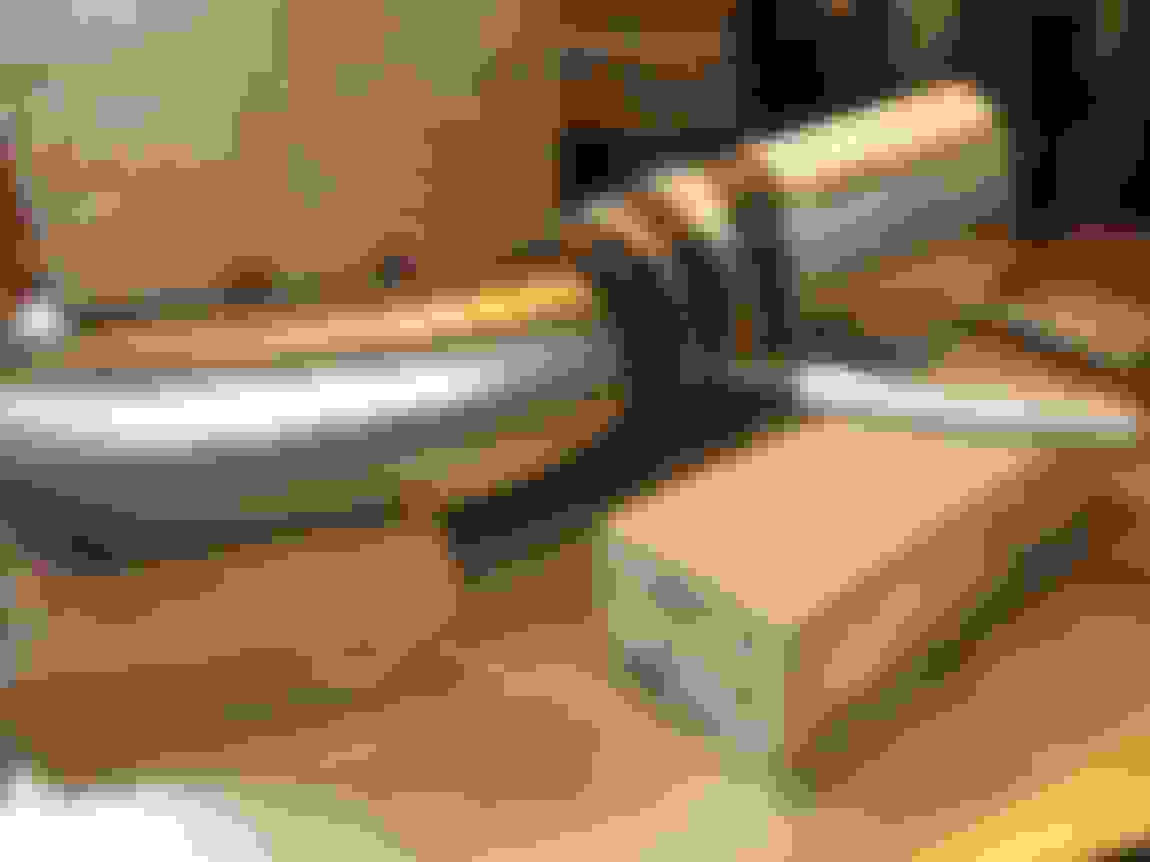
And now things get serious. Not a lot of room in here. Because I had no idea what the shape would, instead of guess-cutting stainless I instead made up the downpipe from existing SS cutoffs and some easier-to-cut aluminum tube. The straight aluminum tube right next to motor mount will end up being some round straight that I'll squish oval for more clearance.
This is about a 3/4" air gap between the round aluminum 3" tube and the steering box, and the aluminum section will be squished-oval pipe that I'll then heat wrap and then add a heat shield on the backside between the downpipe and the steering box. I'll be routing the power steering lines over the downpipe, close the block, and covered in some legit DEI high-temperature heat protective sleeving.
Since Clint is so good at writing up how-to's, I thought I'd share some of my methodology too. This is how I route pipes in complex areas. Since I had a bunch of aluminum straights and bends I try to use those to test cut and hash out routing if I'm really not able to picture how it's going look in my head.
I use electrical tape to temporarily hold together the sections.. it's easy to stretch a bit and sticks well enough, and is reusable a handful of times if it doesn't get greasy on the sticky side.
Once I finalize a section, if there's an aluminum piece spliced in the middle I angle the section appropriately and use a large block as a height reference, and draw a line across the 3 members....
Remove the electrical tape and the lines are still present but not as well defined....
Mark a nice straight line on the stainless piece to get spliced in...
Extend the lines and throw the replacement piece in there...
Then start tack welding the sections together one pair at a time. Probably one of the most helpful things for welding is having a bunch of miscellaneous steel/aluminum medium and big blocks to adjust heights, support things, etc. Also especially helpful to have an assortment of thin gauge sheet/plate to slightly adjust/shim the heights of multiple pieces, etc...
Case-in-point, sometimes you have to get fancy and creative for supporting weird angles... at least when you're working at home and don't have the same awesome fixturing table that you have at work...
And sometimes something is just so awkward that you have to hold it by hand and hope that you can squeeze in a filler-less fusion spot weld. This is especially true when you tack weld on one side of a weirdly shaped tube and wait too long after, the tack cools and shrinks and then you have to put some body weight into closing the gap again and fusion tack weld on the opposite side of the first tack weld...
Left the bottom end of the downpipe as aluminum for now while I figure out what oval/bend shape I want snaking past the steering box...
Downpipe is close to the exhaust manifold, but it has about 1/4" clearance which is more than enough for heat expansion and installation misalignment...
Pretty decent air gap for cylinder #1 spark plug wire, but I'll still cover it in heat protective sleeve. I'll also be running this plug wire directly down and underneath the motor mount, close to the block, but naturally heat protected this whole length.
Like cylinder #1, I'll wrap cylinder #3 spark plug wire in heat protective sleeve and ziptie the wire to the cylinder #5 wire to keep it out of the way of the downpipe.
I might have missed it, but why did you cut the top off of the core support - IC (inlet piping) fitment?
I cut the core support out to make mockup easier, but also so that the full-width intercooler that has yet to be made can simply be lifted up and out, without having to take off the grill or bumper or any trim to remove, vs removing from the front. I'll make a bolt-on top brace that links the two sides of the existing core support, and hugs the final shape of the top of the intercooler and the center top outlet.
Roxie is getting the full twin bypass surgery and I'm loving every moment of the operation! Luckily she's got a skilled surgeon.
You might want to swap to some shorter bolts on your upper control arms so you can get them off if you need to without removing that exhaust. I'd also suggest a heat shield over the power steering lines.
That exhaust is pretty sweet, but the obvious question is: can it cook a hotdog?
I want to make one of these for track days. Breakfast burritos in the morning or hotdogs for the afternoon. I knew a few guys that made these for wheeling - always a conversation piece come lunch time - pop the hood and pull out some "piping" hot food. The one in the video is stupid small though. You need one for each side and enough room for a couple burritos each so you can cook for your friends.
I'll definitely be covering the power steering lines and oil cooler lines with some high-temp sleeves of some sort, as well as exhaust-wrapping the driver side downpipe in the offending areas. I'll also weld on some bungs to mount comprehensive stainless sheet heat shielding on the motor mount and steering box sides of the downpipe.
I was leaving the UCA bolts long for the time being while I figured out the downpipe routing, then will swap to shorter bolts once I figured out my "worst case" clearances.
Anyone have any good experience with particular heat protection/sleeving? I previously had both name brand and Summit brand aluminum foil heat sleeving and after all the heat cycling the aluminum started flaking off as shown in a previous post.
I'm thinking something along these lines, but getting totally lost in all the different brands/options:
I can't recommend a specific wrap, but have you thought about making some sheet metal shielding? Search for aluminum "embossed heat shield" (it's affordable on ebay). Wrap is OK for radiant heat, but if you build a shield that's spaced away, it can both block radiant heat and conduct heat away from the area while allowing air flow around the areas that need to stay cool. You can work with it just like sheet metal, including bead rolling, edge forming, etc. Used sparingly, it looks bitchin'. Wrap has it's place too, but I don't have enough time on mine to tell you if it's any good.
Haha... Clint, the several times I've mentioned "heat shielding" in the last couple posts, I've been meaning exactly like that. There will be formed (by me) heat shields between the downpipe and the steering box, downpipe and motor mount, and between the downpipe and the oil cooler and PS lines wherever they may end up being.
I plan to do heat sleeving in addition to shielding.. shielding is great for redirecting immediate high heat and creating that thru-flow air gap that you mentioned, but there's no question that the ambient temp under the hood is going to be high, and I'd like to insulate the power steering and cooling lines as much as possible from that high ambient heat.
I plan to do similar design as what I had on my previous setup, but maybe try the formed aluminum sheet that you posted a link to:
Found something neat today for the GM Type II power steering pump, thought it might be beneficial for others. But first, a little background...
The first time I redid my accessory drive, call it Version2, I went from a trimmed cast aluminum truck bracket for the alternator & old Saginaw pump to custom plate bracketry to hold a newer GM Type II PS pump. When I was researching this I originally wanted to use a straight adapter fitting to go from the pump M16 port threads on the outlet to -6AN male, and then a 90* hose end or adapter, to make sure the pump outlet flow is nice. I ended up not having the room to loop the height of an adapter fitting and 90* end, as well as the minimum hose bend radius under the bracket for the alternator. So instead I used the standard M16 banjo fitting, which I was never really a fan of, thinking that maybe the small banjo bolt holes and sharp geometry could introduce aeration and maybe cavitation and pump whine.
The benefits of a banjo style fitting are: 1) tighter fitting sizing, and 2) companies like DSE etc sell a banjo fitting brazed or welded to nice pump-hugging stainless tubing that wraps around the side of the reservoir for tight fitment. This is great and all for tight areas, but those pieces are expensive at $70-100+, and still have the banjo fitting which may or may not actually affect flow.
DSE power steering hard line and fitting option...
Danchuk hard line...
Holley hard line...
So this morning I was helping troubleshoot a coworker's 1988 Jeep Grand Cherokee, and noticed that its power steering pump has a very similar tight-bend steel tube wrapping above the reservoir, but the part that threads into the pump outlet is an awesome straight fitting! The pump appears to have a straight adapter fitting in it, and every year of power steering pressure hose that I looked up appeared to be the same o-ring fitting, with variations in the tube bend path.
Some research:
Jeep Grand Cherokee, '84-'86, 4.0L engine, little hard to tell which end goes in which direction, also very hard to find any pictures or eBay ads for this model year range...
Jeep Grand Cherokee, '87-'90, 4.0L engine, wraps around the top and back of the reservoir, then straight down (hose end on right side of pic). ACDelco 36358690 or Gates 358690...
Jeep Grand Cherokee, '93-'98, 4.0L 5.2L 5.9L engines, points the hose horizontally to the driver's side...
Jeep Grand Cherokee, '99-'04, 4.0L engine, points the hose down behind the reservoir like the '87-'90 hose. Finding part numbers of Gates 353090 & Gates 365606...
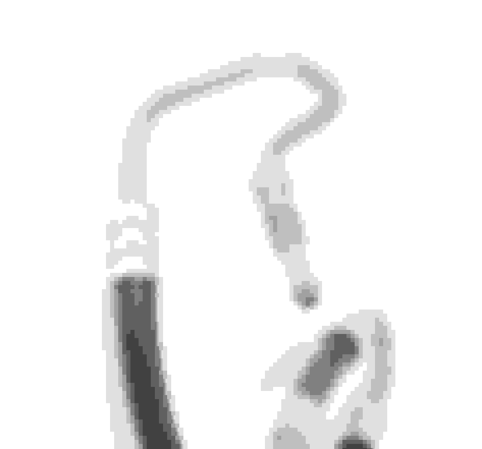
I'm not sure I follow where you're going with this, but the image below does NOT show an inverted flare fitting:
That looks like an o-ring style form on the tube end, similar to GM push connect like what's commonly found on the fuel rail, but with a threaded nut for retention. The tube form just creates a stop and usually adjusts the end size slightly to make sure an o-ring will make a good radial seal.
*EDIT* Yeah pretty sure that is an SAE o-ring pilot aka o-ring bump style of tube form on the end. Take a look here and search for "SAE o-ring pilot" for a table of info. http://www.pirate4x4.com/tech/billavista/Plumbing/
I would think an inverted flare adpater would be very tight fitting to the pump and you could use a 90 degree sweep fitting for your power steering hose.
Last edited by -TheBandit-; 02-16-2018 at 03:03 PM.
Gotcha. I'd be willing to bet there is an o-ring pilot to inverted flare adapter that would minimize the fitting length since most of the fitting would tuck down inside the port. If there isn't you could machine one yourself
*EDIT* I agree with you on banjo fittings. They must be reasonably reliable because they use them on disc brake calipers, but I hate the idea of using two face seals (twice the opportunity to leak in my opinion!) and in this application having no anti-rotation to keep the fitting from backing off. Plus the flow path sucks going down the center of a bolt through two small passages and around the inside of the banjo. That will lead to heating of the fluid as it recirculates in the steering system, but I don't think it adds any significant risk of aeration or cavitation really.
*EDIT 2* I bet if you find a good hose or hydraulic shop nearby, they can help you get the right fittings crimped onto some hose that would fit directly into the port on the steering pump. Most likely it's a catalog item for Parker Hyrdaulics, Gates, etc but you probably wont find it at your typical auto parts joint (other than as part of an already-assembled hose).
Last edited by -TheBandit-; 02-16-2018 at 06:00 PM.
Clint I coulnd't agree more with your points about the banjo fitting. It's hard to argue the logic that it's "tried and true" when companies like DSE etc use and sell it, but in my engineering mind I would just rather the flow path be smooth and friendly. Power steering fluid already has a tough life with getting hot and has a tendency to aerate and whine with even a moderately decent bleed, so I'd rather just reduce any reason for that stuff to happen.
For the adapter fitting you mentioned, the pump bodies as sold by most places already come with an adapter installed that has a 5/8-18 SAE o-ring pilot female to M16x1.0 male. Fingers crossed, any one of the above OEM assemblies should thread right into said fitting that's pre-installed into an aftermarket, repro, or takeoff pump. I of course removed this adapter fitting to install said banjo fitting, which has a M16 thread that screws directly into the pump body.
Funny you mention about the 2X seals that can leak on a banjo fitting.. when I first put my GM type 2 pump on, I tightened the absolute crap out of the banjo bolt and guess what.. one or both of the banjo seals leaked. I was so pissed because the accessory drive was all back together and I was so ready to start driving the car again, and it started dripping P/S fluid pretty badly. Funny I just let it sit and idle while I angrily stared at it for about 5 minutes, and then drove it around the block anyways just to see if the assist level was okay.. and the leak stopped! I guess the setup was new and needed a heat cycle to deform the aluminum washers a bit, I ended up trying to re-tighten everything after that but nothing seemed to budge.
I'll investigate the likelihood of a Parker crimp fitting being available to make a custom hose. I already browsed the local hydraulic shop's brand catalogs and saw a lot of metric port and BSPP ends but nothing resembling an o-ring pilot style. I may get a new ACDelco hose assembly and chop it up and weld on a -6AN fitting either before or after the flex line, space permitting. Or instead of welding, I might attempt to flare a tube part of the assembly with the Eastwood kit that I ordered a couple days ago!
Another decent day in the garage today, ended up spending a bunch of time figuring where wiring, breather hoses, fuel FPR and hoses will go, etc. All this revolved around getting a new intake..
I've been kinda mediocrely pleased with the truck intake this whole time. I originally liked it because it's what I had, and with some trimming I thought it still looked kind of "OEM". But with time and all this attention spent on perfecting the aesthetic of the twin turbo setup, I've been intrigued with getting a nicer looking low-profile car intake.
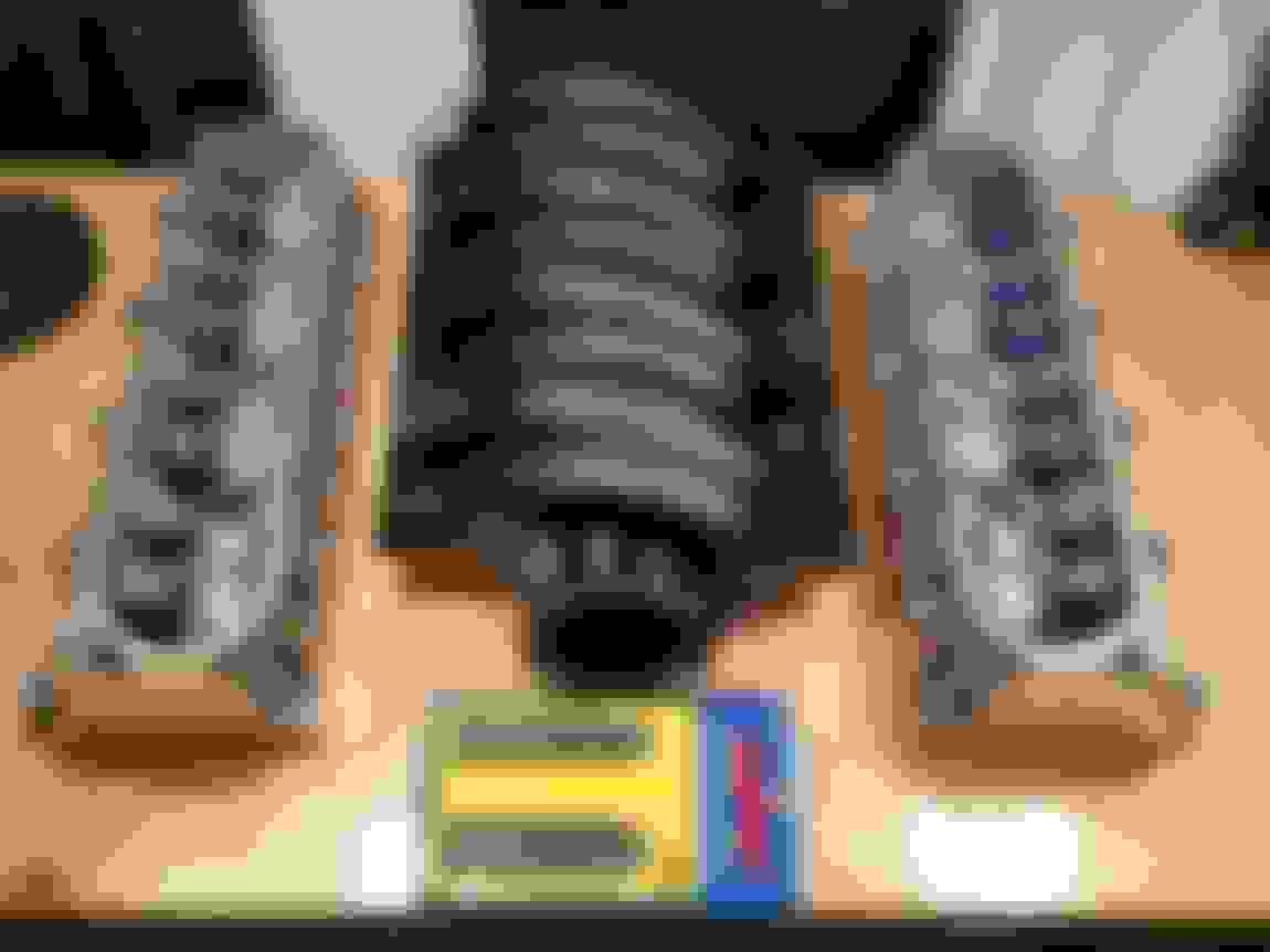
In my research before deciding to go with twins, I decided that if I were to ever justify replacing the heads, I wouldn't go all the way with crazy CNC AFR heads but instead would go with stock GM LS9 heads due to the better/stronger A356 material they're made of and the casting method, the [slightly] thicker decks, and the all-cool [slightly] larger titanium intake and sodium-filled exhaust valves. Well I found a good deal on BNIB GM CNC LS9 assembled heads... why not! Their combustion chamber size is 66.5cc compared to my old 70.5cc 317 heads, so that will bump my compression up from 9.0:1 to 9.4:1.. I don't foresee this being an issue. Bonus for this is if I end up stroking the engine in the future, I won't have to settle for 8.0:1 to 8.5:1, I could get closer to 9.0:1 with a 4.0" stroke.
This allows me to run an LS3 intake which looks much nicer in my opinion (hey.. I have to pay attention to form sometimes!) and requires a 4-bolt 90mm throttle body which is close to the 3.5" charge piping I'm running. The rectangular ports look honestly almost twice as big as the cathedral ports.. I personally don't see a downside to the upgrade... if I can build the same power but at 0.5psi, 1psi, or even 2+psi less boost produced by the turbos, then that's a win in my books, not to mention the better heat properties of the head material.
I did some reading thinking I'd be smart, and preemptively purchased a 2008+ "gold blade" LS3 throttle body (GM p/n 12605109), reading that its blade is reverse-sweep compared to the previous 2005-2008 "silver blade" LS2 throttle body (GM p/n 12570790) but that Holley is compatible with it. Somehow in my hours of research beforehand I didn't come across the fact that apparently the later "gold blade" TB had much weaker servo motors than the "silver blade", and has a tendency to have the TB blade get forced/stuck open under "high boost" when the foot is taken off the pedal. So looks like I'll be returning the later LS3 TB and buying an earlier LS2 TB.
Checking the angularity of the silicone coupler and the 3.5" piping, with the intake now a bunch lower. It was actually quite easy to stretch the 3.5" 5ply silicone double hump coupler over the 100mm throttlebody OD, so it's nice I can reuse that coupler. With some ovalization of the charge pipe over the radiator I don't think the intake piping angles will look too whacky...
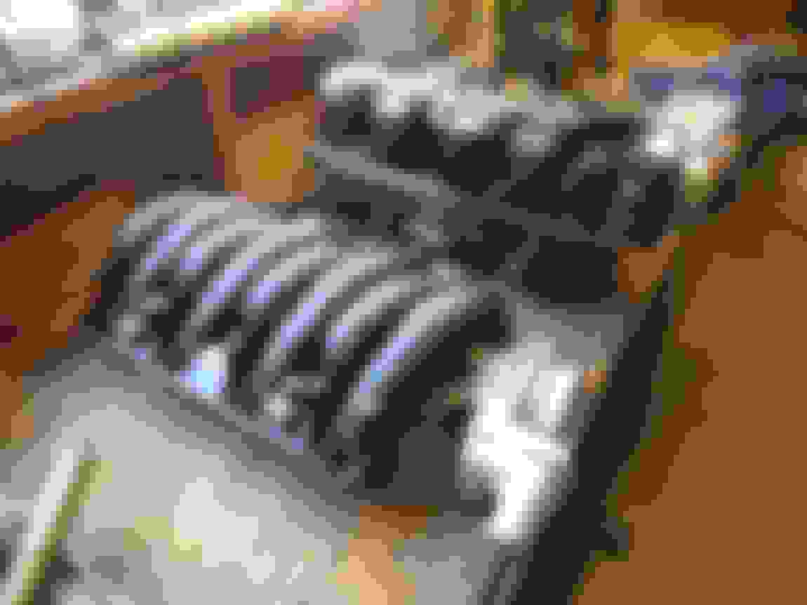
A decent shot to show how close I got the placement of the wastegates, the clocking angles of the wastegate domes, and the angles of the wastegate dump pipes (with flex joints).
Also got started on the passenger side wastegate dump pipe into the downpipe.. I'm pretty happy with it but will think about it a bit to see if I want to slacken out the angles of the bend going into the downpipe...
Valve covers on the list of cosmetics too? Not critical to what you're doing with the twins, but long term that would help clean things up further. It's looking very, very good. This will be the Nova people dream about. I see many magazine shoots in your future.
Thanks Clint.. to me it's just a project car haha, but one that keeps getting continual improvement.
I agree with the valvecovers comment, although I may not find them as offensive. I do still really like the wrinkle finish.. I feel they turned out surprisingly well despite being from a can and not heating in an oven. I really like your "Chevrolet" covers with the lettering sanded shiny.. I may do something similar but try wrinkle coat again instead of just gloss paint.
I used a textured powder coat that is sort of a satin finish. It's not quite as textured as the VHT wrinkle, but not smooth either. The wrinkle paint would definitely look good. I think you should paint them the body color of the car - some bright orange ought to liven things up in there.
I used a textured powder coat that is sort of a satin finish. It's not quite as textured as the VHT wrinkle, but not smooth either. The wrinkle paint would definitely look good. I think you should paint them the body color of the car - some bright orange ought to liven things up in there.
To be honest I'm not a huge fan of trying to tie engine bay into body color... whether it be the firewall or subframe painted body color (no offense), or matching valve covers (yellow TT nova comes to mind). I prefer it all to be satin black, brushed aluminum, or brushed stainless.
That being said, I was tossing around the idea of painting the firewall and inner fenders gloss light grey, because race car. I'm removing the heater and making a cover panel, need to repair some DOT fluid firewall paint damage, and paint the inner fenders after the modification... so engine bay "background" paint color is still up in the air.


 02-12-2018, 08:27 PM