LQ9 6.0L PT88 w/ Truck Manifolds in an FBody Build w/ Pics
 03-05-2009, 03:32 PM
#21
Truck Sponsor
iTrader: (11)

Join Date: Sep 2006
Location: Wichita Falls Tx.
Posts: 3,122
Likes: 0
Received 0 Likes
on
0 Posts
It's funny because I was looking at the t4 flange thinking "how the hell can you make any power through this little hole?". I am going from true dual 3" exhaust with 2" primary headers to this stuff. It's an entirely different strategy that is forcing me to have lots of faith in what I read.
 Good luck with your build.
  03-05-2009, 05:41 PM
#22
TECH Regular
iTrader: (5)
Join Date: Jan 2003
Location: South Florida
Posts: 429
Likes: 0
Received 0 Likes
on
0 Posts

It's funny because I was looking at the t4 flange thinking "how the hell can you make any power through this little hole?". I am going from true dual 3" exhaust with 2" primary headers to this stuff. It's an entirely different strategy that is forcing me to have lots of faith in what I read.
03-05-2009, 07:35 PM
#23
yeah, it's a different animal all together. In fact the people that have the most trouble with turbo set-ups are usually the guys over complicating things. you know Jake runs 2.25" pipes to the T3 turbo housings and 2.50" pipes to the rear bumper. all small compared to the typical 147mph car.. don't out think yourself.
 but he set the bar high thats for sure
03-06-2009, 08:24 AM
but he set the bar high thats for sure
03-06-2009, 08:24 AM
#26

I got my flow matched 80# high impedence injectors today from FIC Injectors. They came with a flow sheet (matched) and 2 of them flow about 4 CC's more marked for the notorious #7 & #8 cylinders.
Oh, and I also got my truck manifolds today. Flanges are running behind.
I also sent out the FiberTuned intake to have the divider plate removed which was causing most of the flow restrictions. They are also going to brace it up a little for the boost as I heard from another tester that it was flexing a bit at about 15 psi (which I wont see until I get some rods, pistons, and my heads on it). If you're curious as to what I am talking about. The answers are here https://ls1tech.com/forums/generatio...-pictures.html
03-07-2009, 07:11 AM
#29
Thanks for the help yesterday Darin! I intend to bring my box of parts over to my car and get some more stuff attached today. I'll take some pictures and see how our "air math" worked out. I would rather have twice as much stuff than come up short.
03-07-2009, 08:49 PM
#31
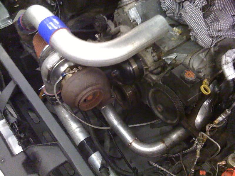
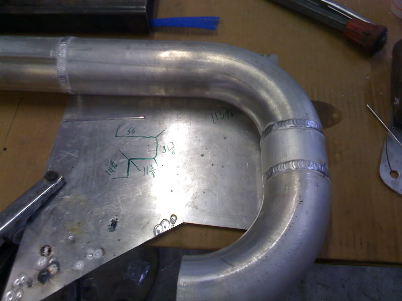
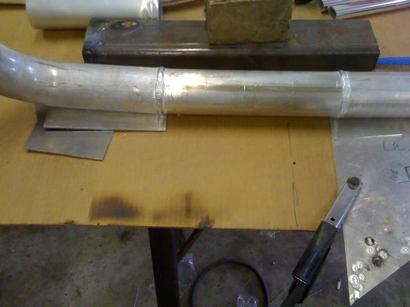
This afternoon/evening was very productive. We got the charge pipe from the turbo to the intercooler all cut and marked for welding . The other side is almost done but I cant finish it until I get my intake back as I am not sure as to where exactly the throttle body opening ends up and on what angle.:shrug:
So here are some pictures:
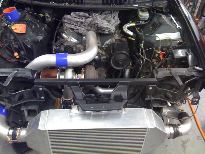
I got extra stuff. The ridge on the downpipe vband flange was way too big. Gonna have to track something down for that. I dont think that machining it down would allow it to seal properly and the channel in the clamp would be too wide and would likely bottom out before tappering all the way in.
. The other side is almost done but I cant finish it until I get my intake back as I am not sure as to where exactly the throttle body opening ends up and on what angle.:shrug:So here are some pictures:
03-08-2009, 10:47 AM
#32
TECH Regular
iTrader: (5)
Join Date: Jan 2003
Location: South Florida
Posts: 429
Likes: 0
Received 0 Likes
on
0 Posts
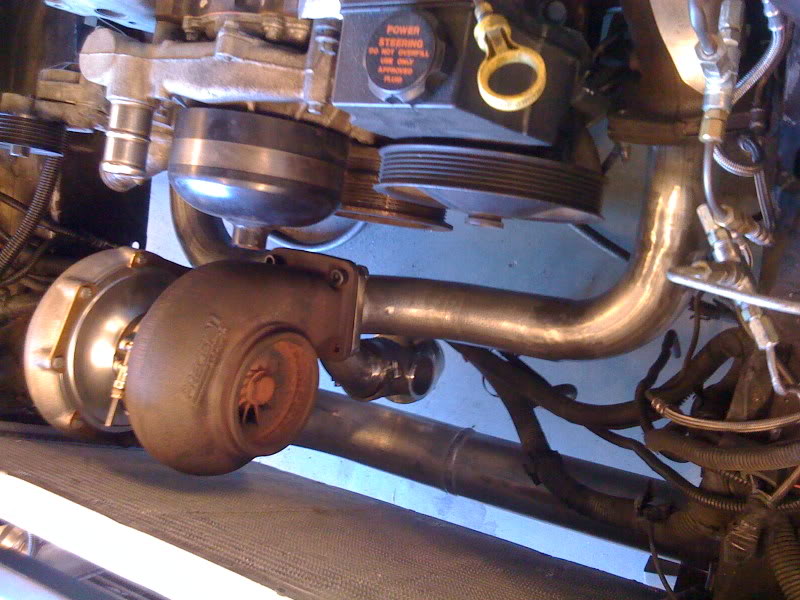
hmm. can you measure the outside diameter of the turbo outlet. Compare it to the flange i gave you which is roughly 4.75" OD. You may need a 3.5" flange which has an OD of 4.25". Also make sure the oil inlet is at the 12 o'clock position and the drain at 6. looks like it's rotated a bit but should be as verticle as possible. otherwise it looks like the intercooler to TB pipes turned out pretty sweet.
03-08-2009, 07:54 PM
#34
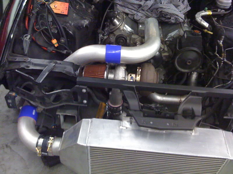
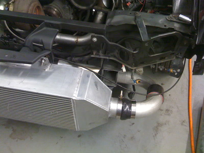
Got my buddy Dave to TIG weld up the aluminum pipe going from the turbo to the intercooler.
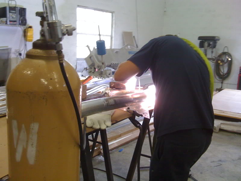
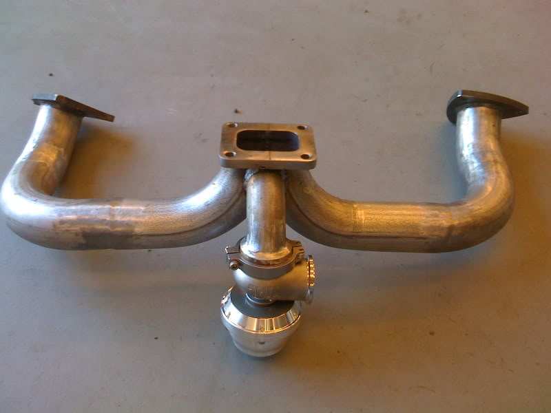
In the mean time, my buddy Joe was welding and polishing the hot side and adding the tube for the wastegate.
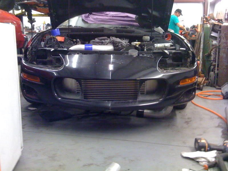
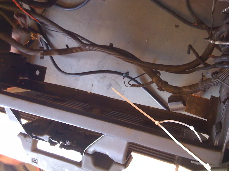
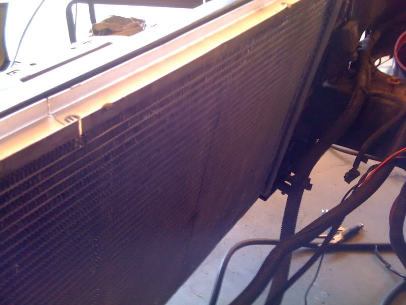
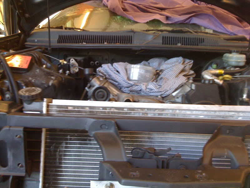
Once we got everything in with the radiator and all we were looking at how high up the radiator was sitting. We realized that we hadn't tried closing the hood. No go. So I cut the bottom support out and Joe made a couple of brackets to hold the radiator up.
In the mean time, my buddy Joe was welding and polishing the hot side and adding the tube for the wastegate.
Once we got everything in with the radiator and all we were looking at how high up the radiator was sitting. We realized that we hadn't tried closing the hood. No go. So I cut the bottom support out and Joe made a couple of brackets to hold the radiator up.
 03-09-2009, 07:12 AM
#36
hmm. can you measure the outside diameter of the turbo outlet. Compare it to the flange i gave you which is roughly 4.75" OD. You may need a 3.5" flange which has an OD of 4.25". Also make sure the oil inlet is at the 12 o'clock position and the drain at 6. looks like it's rotated a bit but should be as verticle as possible. otherwise it looks like the intercooler to TB pipes turned out pretty sweet.
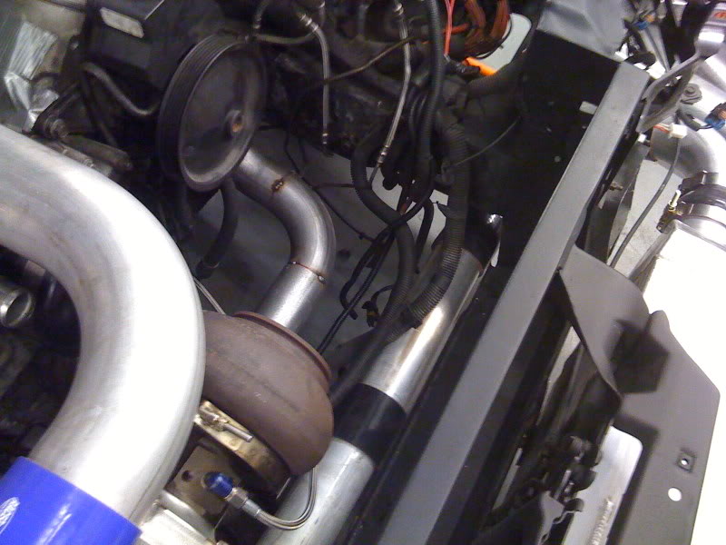
I bought a turbo kmember so I wouldn't have to run the DP right next to the motor. I found that the extra space to the outside of the motor mount tower on the passenger side is blocked by the exhaust manifold. There is more space on the drivers side.
 03-09-2009, 08:31 AM
#38
Hopefully
Just got done painting the (50 feet of) wrap so the hot pipe is all done.

Sold my dedicated nitrous fuel cell last night. I used that money to order the pusher fans (FLX-240), turbo heat shield, boost gauge and T4 flange gasket. I got the exhaust flange gaskets today also. Getting close.
Just got done painting the (50 feet of) wrap so the hot pipe is all done.
Sold my dedicated nitrous fuel cell last night. I used that money to order the pusher fans (FLX-240), turbo heat shield, boost gauge and T4 flange gasket. I got the exhaust flange gaskets today also. Getting close.