ModularTurbo/CBR F2 Twin Turbo kit install
 05-21-2012, 09:02 PM
#1
Customer: Dan Sobczak
Car: 2000 Trans-am WS6
Existing mods: LS9 cam
Customers goals: 500 RWHP for now with room to grow with supporting mods in the future.
Turbo selection: Twin Turbonetics 60-1 compressor 62mm turbine T4 .68 a/r Ball Bearing Turbos ported covers with anti surge ports
All work performed by Chris @ CBR Performance Products
All Parts sourced From Modular Turbo / Robert Josvai
Dan called us back in January, wanting to turbocharge his car. Dan had some rather strict conditions though.
He stated that he wanted to keep the air conditioning and all other stock amenities. He also did not want to cut the bumper cover for an intercooler. Then he said this, "Rob, my car has 45,000 miles on it and its in near mint condition... I want it to stay that way."
Normally, this would be a huge mountain of difficulty for a 4th Gen owner. The usual route to awesome 4th Gen turbo power involves a cut here, a cut there, and a rather large pile of stock parts including pieces of front bumper cover and radiator support laying in the back of the shop with no hope of ever going back on the car.
A lot of us have been down that road and have the T-Shirt....
Chris and I spoke with Dan at great length about our F2 Twin Turbo kit. We explained how our kit meets all of his goals and then some. He decided that it would be the way to go.
Information about our TT kit can be found here:
www.ModularTurbo.com
We started off by getting the Fuel system ready for boost.
We decided to use 80lb/hr siemens/deka injectors & twin in-tank walbro pumps.
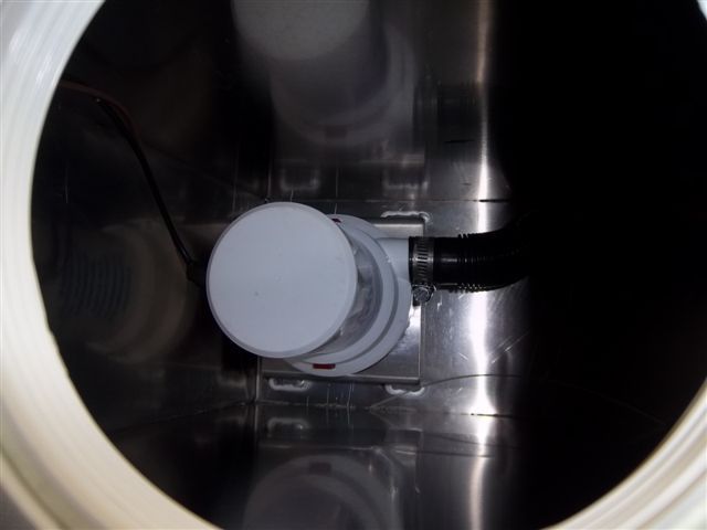
Chris made short work of the custom in-tank twin pump setup.
Here are the pics:
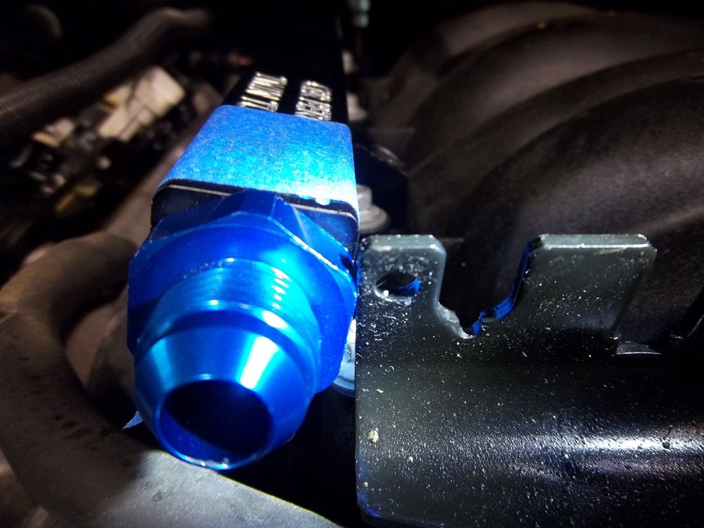
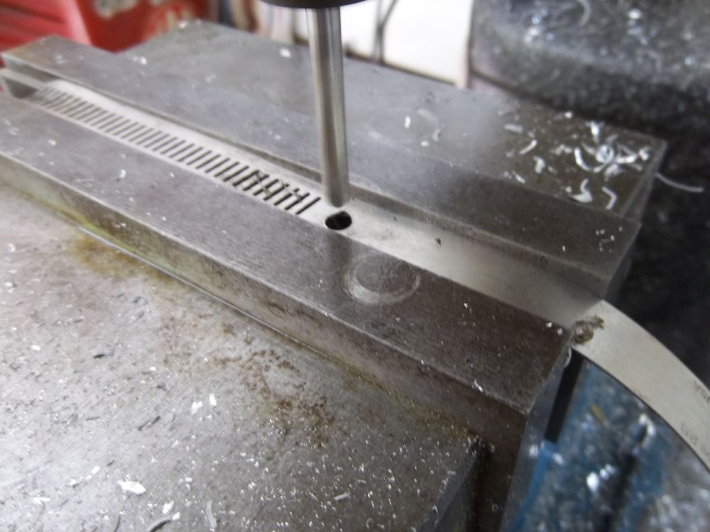
The throttle cable bracket got in the way with this fitting.
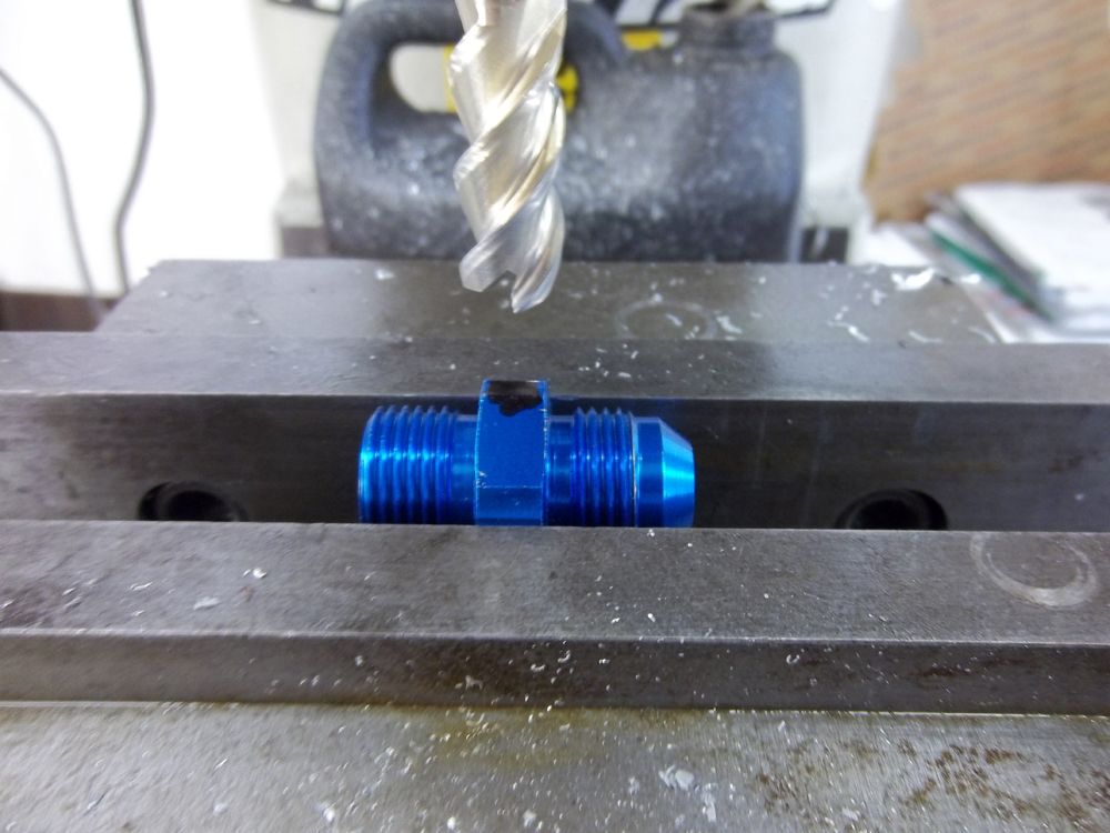
Chris milling it down for clearance.
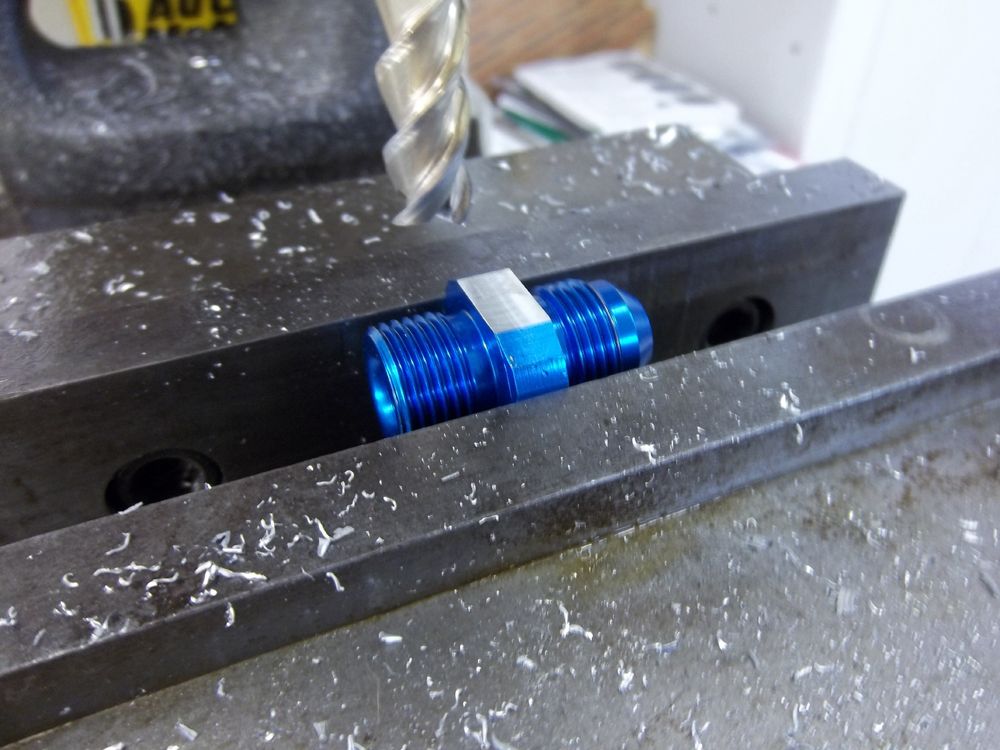
Here is the fitting after the mill work was completed.
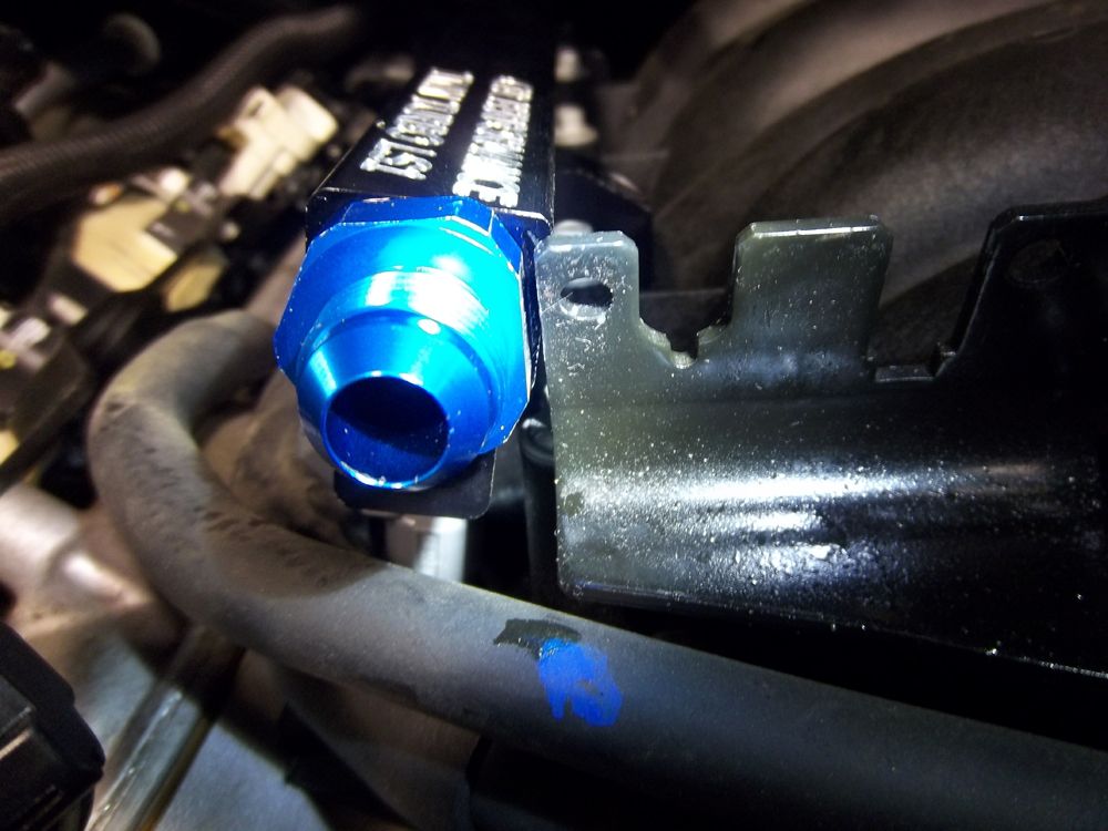
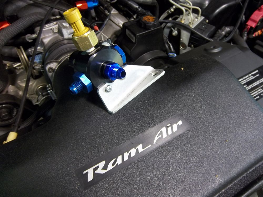
Now it fits! If you look close you can see our new CBR fuel rails. The engraving reads "Twin Turbo LS1".
Here is a picture of the mounting plate that Chris made for Dan's regulator.
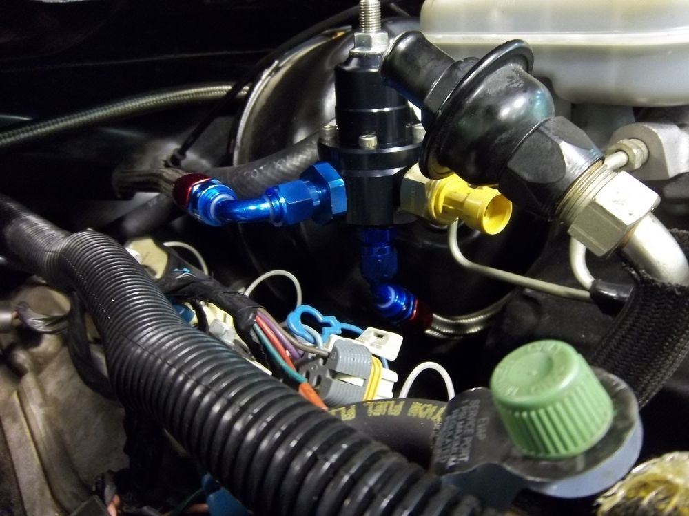
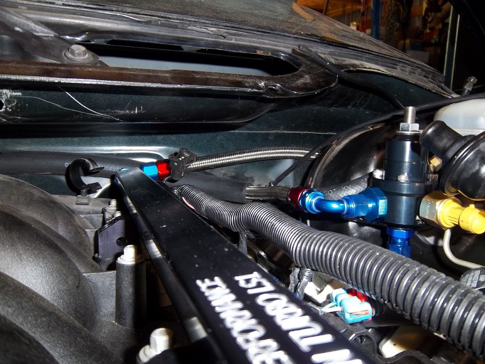
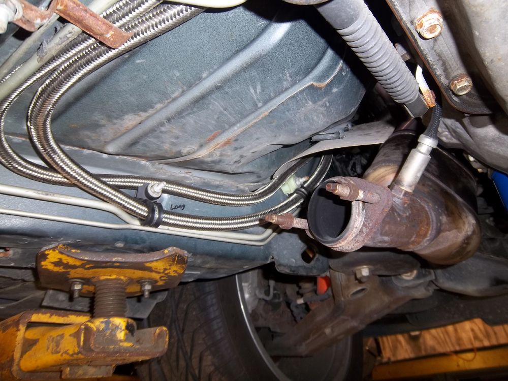
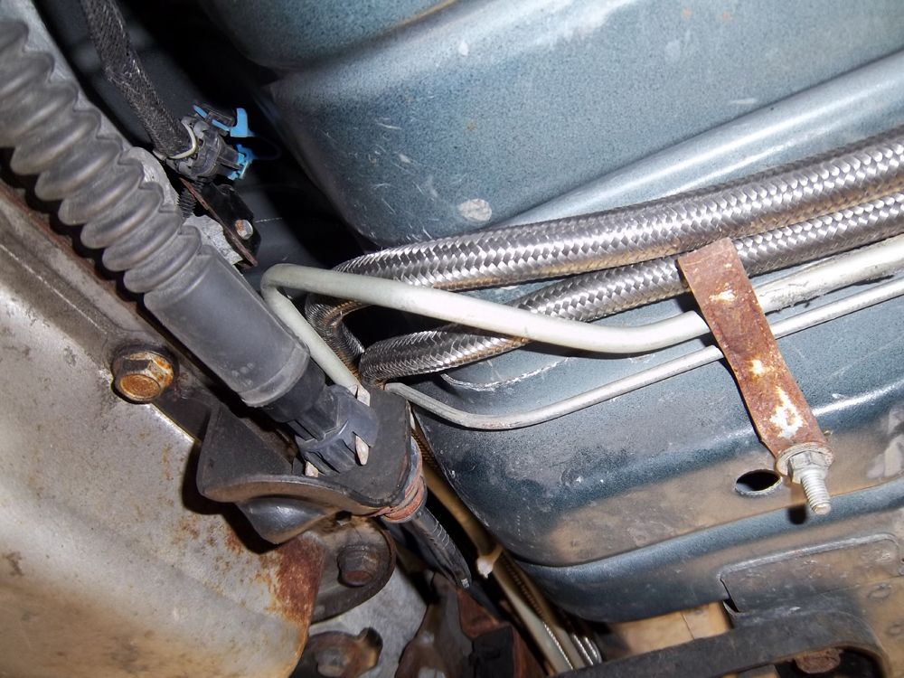
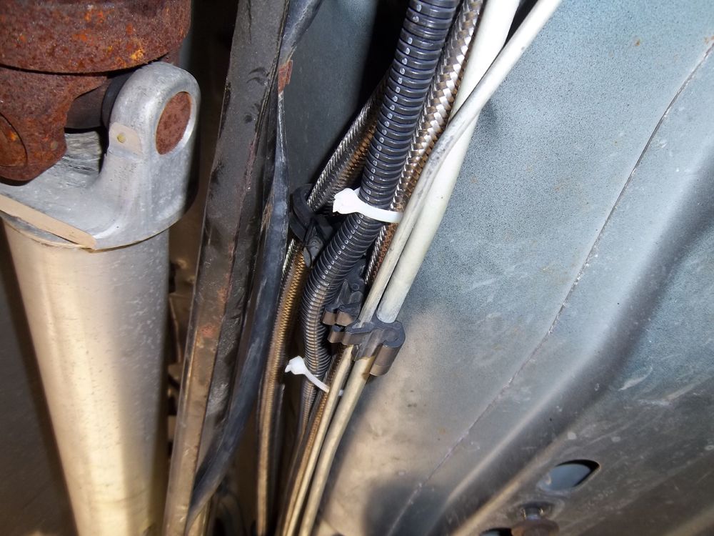
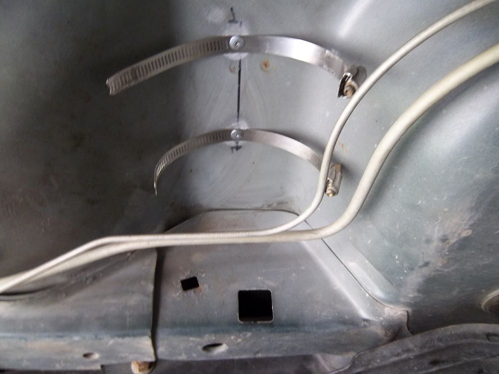
Time to hide some Fuel Lines.
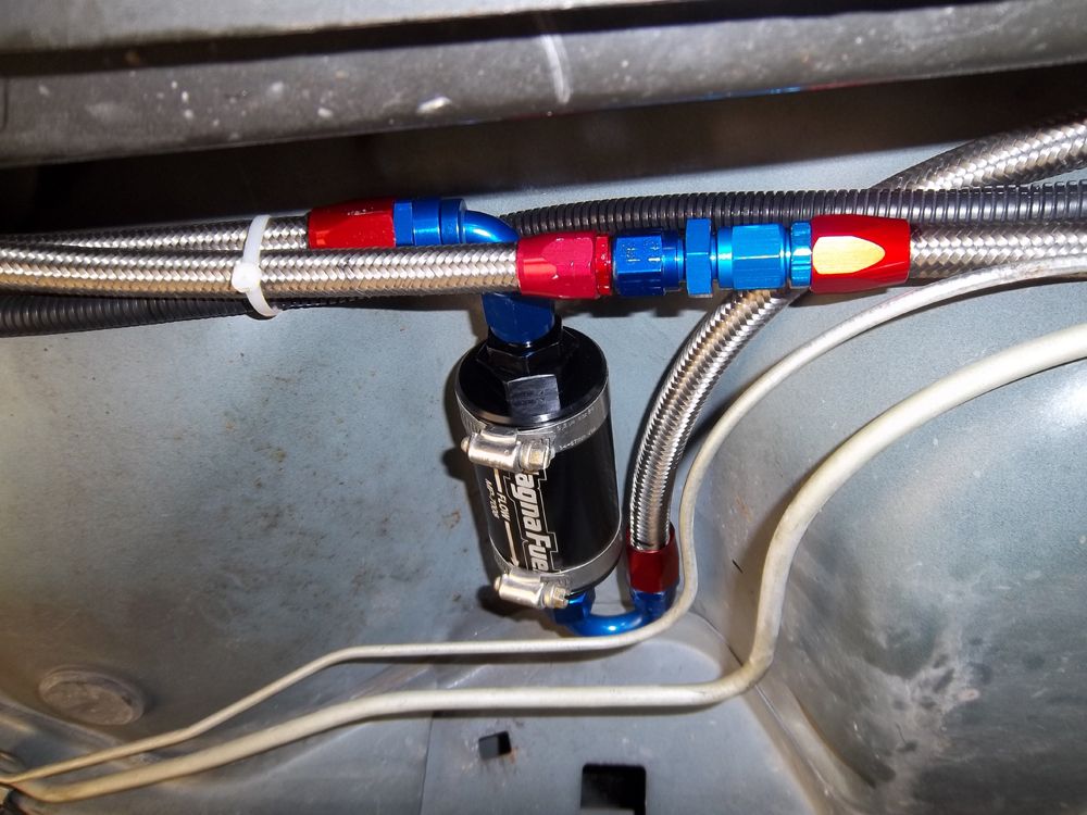
Magna Fuel filter install.
This filter is tucked in the pocket were the stock filter was mounted
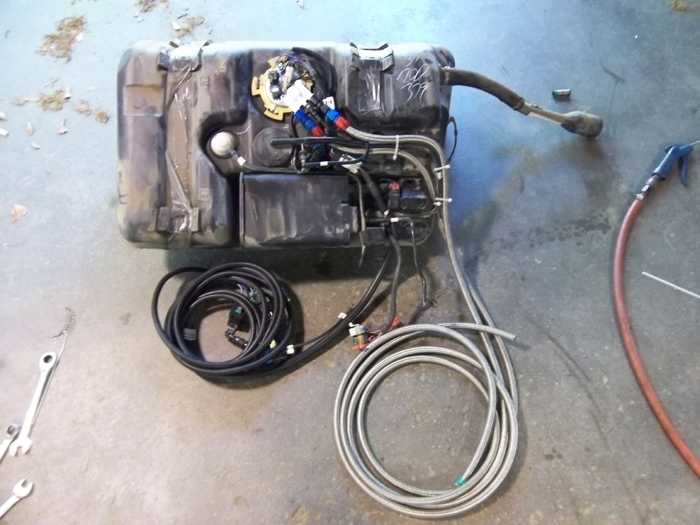
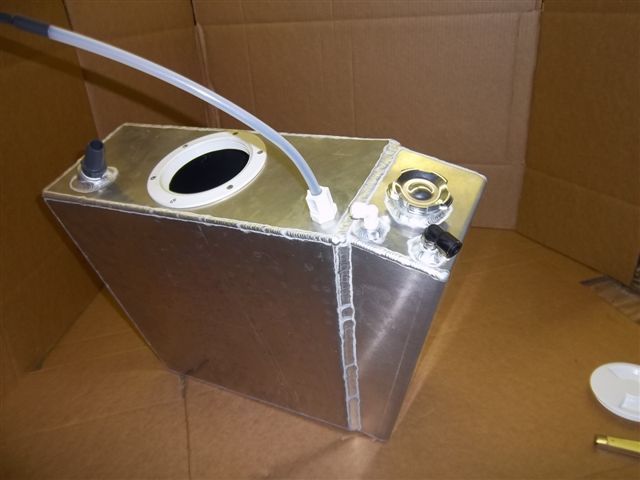
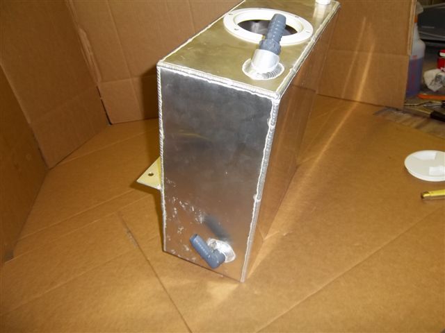
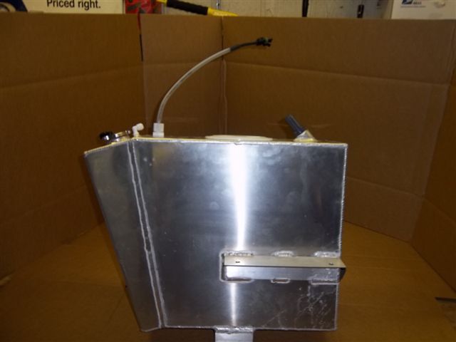
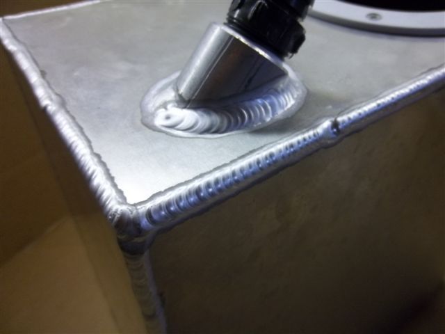
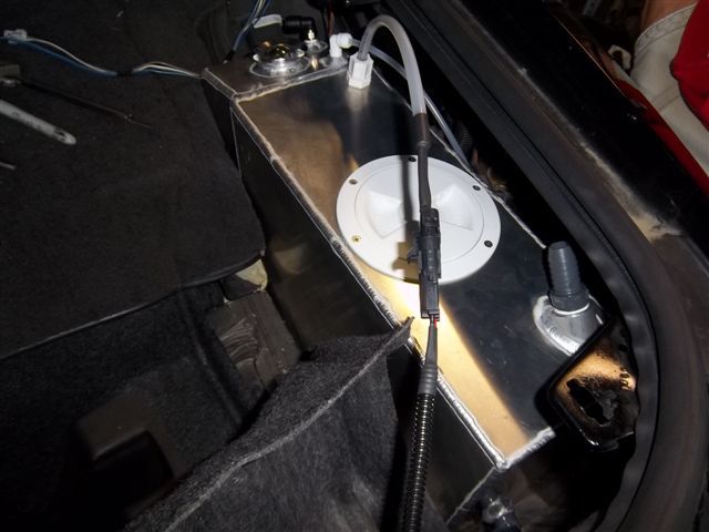
Fuel Tank assembly ready for install.
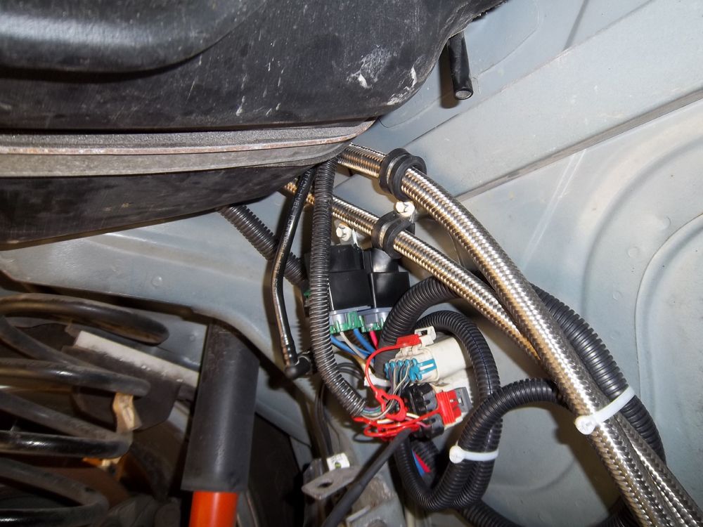
Time to run some power to it.
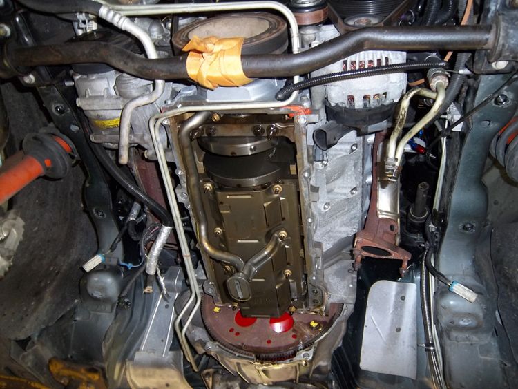
K-member removed and engine resting on the sway bar.
We secured the balancer to the sway bar for some added safety.
Pulling the K-Member this way allows easy access to the oil pan and removal
of the brake lines
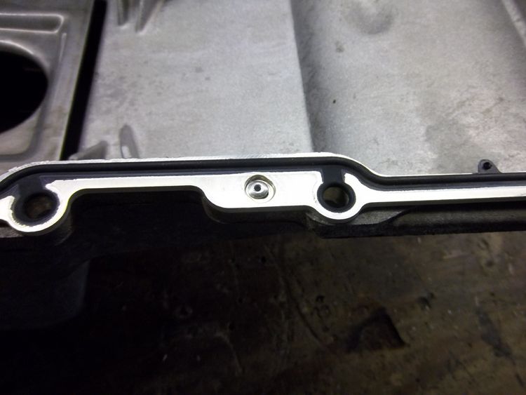
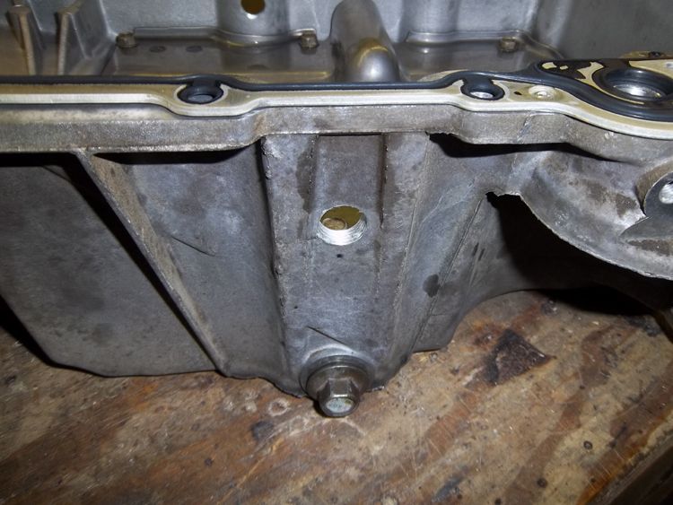
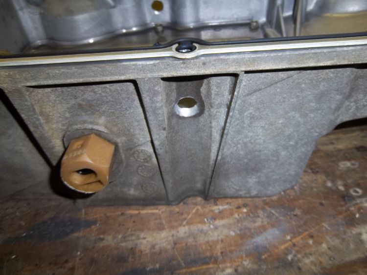
We removed the oil pan so we could tap it for the oil drains.
Notice the Yank 3200 convertor Chris previously installed
Chris is using foil tape to keep debris out of the ABS module
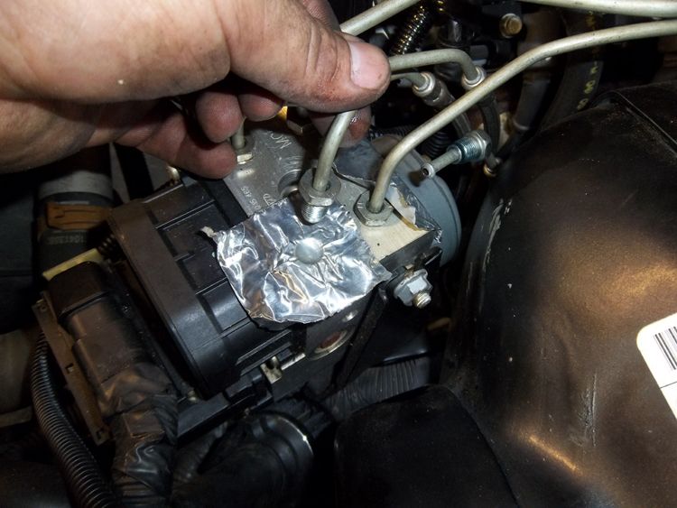
Its a lot easier to get to the brake line clips when the K-member has been removed
Nice and clean oil pan ready for to go back on the motor.
Note: Oil pan baffle is sprayed down with WD40 to prevent rusting
until the motor is filled with oil.
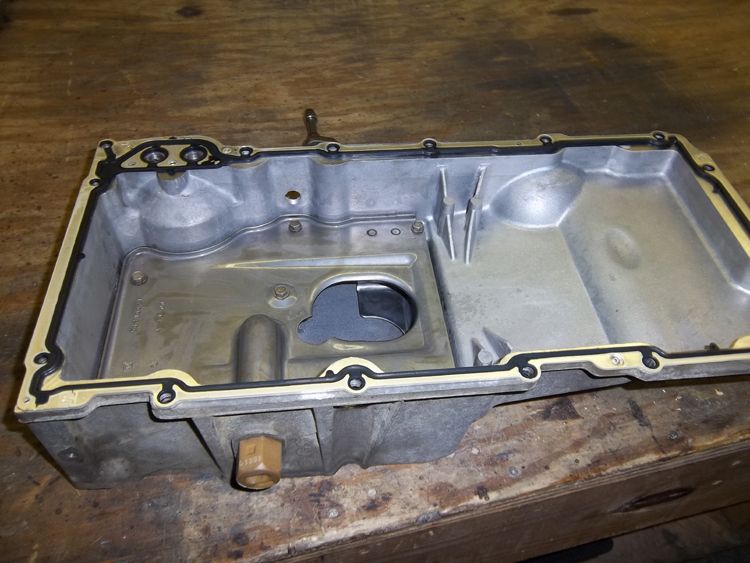
Chris rivets a new GM gasket to the pan just like it was done at GM.
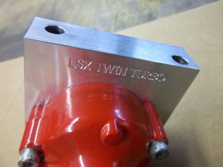
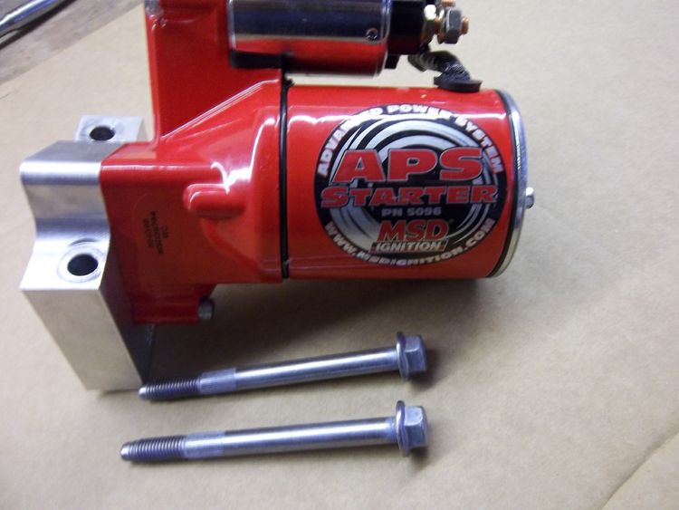
MSD starter with our CNC'd billet head
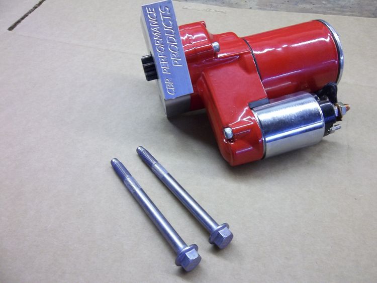
New GM starter bolts with the proper knurl are used. This ensures the starter properly
aligned with the block and flywheel just as GM intended.
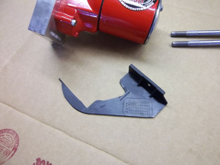
Stock starter Dust Cover must be trimmed to fit
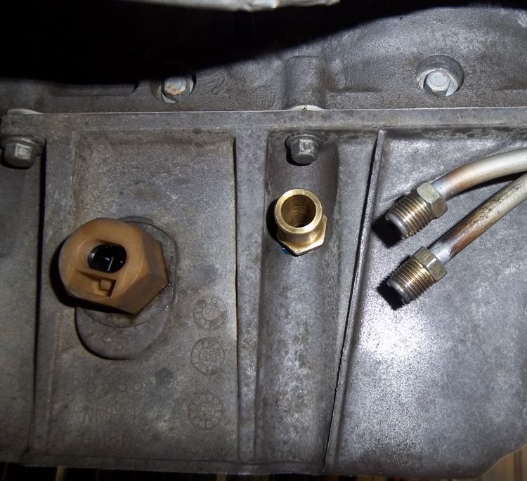
Transmission lines must be re-routed to make room for the starter
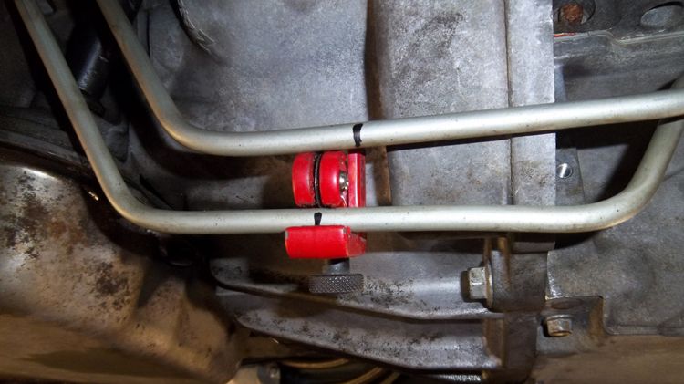
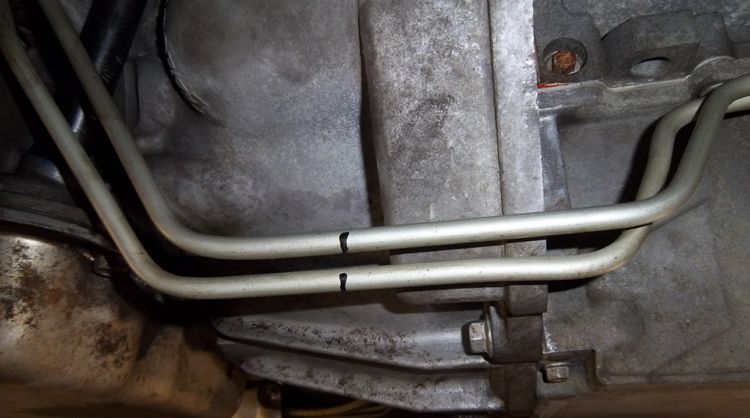
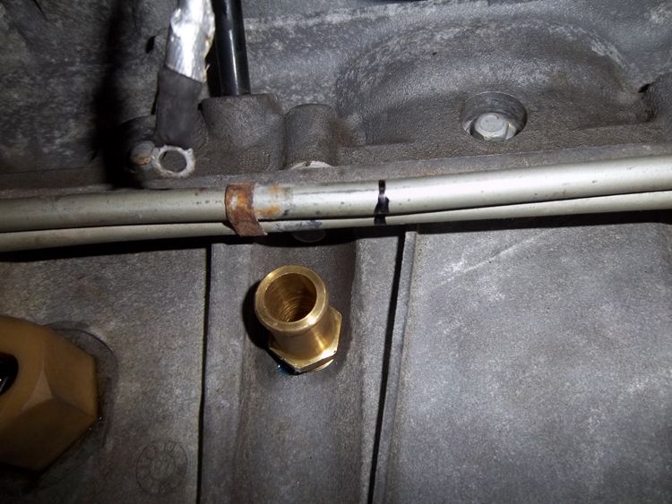
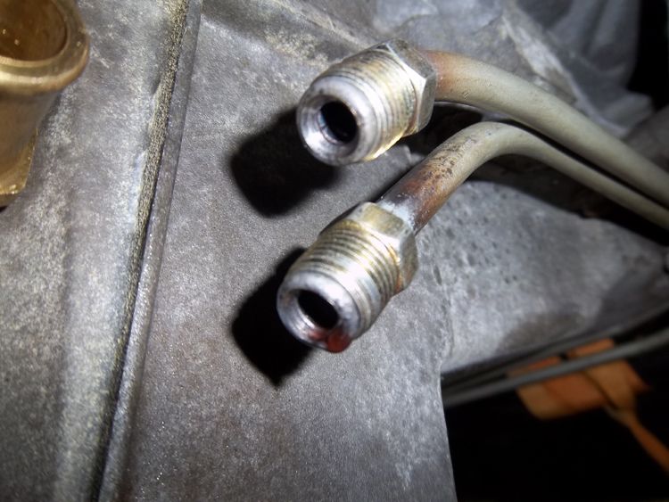
Chris uses tube nuts and puts a 45 degree double flare on the factory lines.
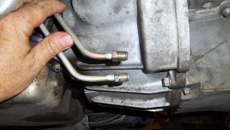
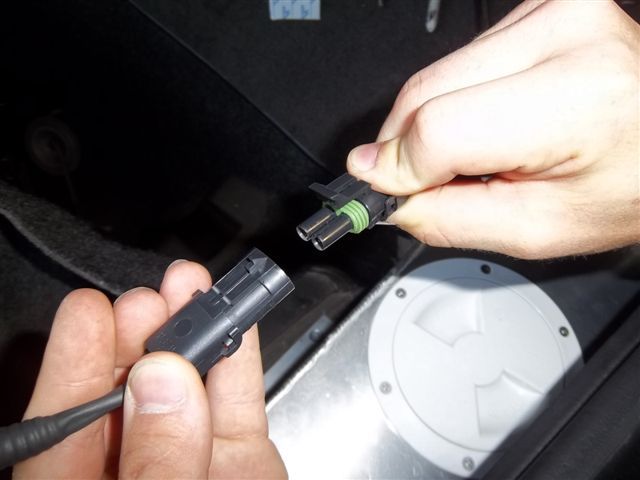
Notice the Crank Position Sensor extension harness, this is included with the kit
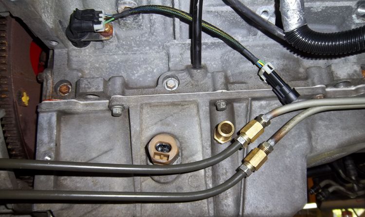
Dust cover installed
That's all for now. We will be posting up more pics of this project as it progresses. So stay tuned.
Car: 2000 Trans-am WS6
Existing mods: LS9 cam
Customers goals: 500 RWHP for now with room to grow with supporting mods in the future.
Turbo selection: Twin Turbonetics 60-1 compressor 62mm turbine T4 .68 a/r Ball Bearing Turbos ported covers with anti surge ports
All work performed by Chris @ CBR Performance Products
All Parts sourced From Modular Turbo / Robert Josvai
Dan called us back in January, wanting to turbocharge his car. Dan had some rather strict conditions though.
He stated that he wanted to keep the air conditioning and all other stock amenities. He also did not want to cut the bumper cover for an intercooler. Then he said this, "Rob, my car has 45,000 miles on it and its in near mint condition... I want it to stay that way."
Normally, this would be a huge mountain of difficulty for a 4th Gen owner. The usual route to awesome 4th Gen turbo power involves a cut here, a cut there, and a rather large pile of stock parts including pieces of front bumper cover and radiator support laying in the back of the shop with no hope of ever going back on the car.
A lot of us have been down that road and have the T-Shirt....
Chris and I spoke with Dan at great length about our F2 Twin Turbo kit. We explained how our kit meets all of his goals and then some. He decided that it would be the way to go.
Information about our TT kit can be found here:
www.ModularTurbo.com
We started off by getting the Fuel system ready for boost.
We decided to use 80lb/hr siemens/deka injectors & twin in-tank walbro pumps.
Chris made short work of the custom in-tank twin pump setup.
Here are the pics:
The throttle cable bracket got in the way with this fitting.
Chris milling it down for clearance.
Here is the fitting after the mill work was completed.
Now it fits! If you look close you can see our new CBR fuel rails. The engraving reads "Twin Turbo LS1".
Here is a picture of the mounting plate that Chris made for Dan's regulator.
Time to hide some Fuel Lines.
Magna Fuel filter install.
This filter is tucked in the pocket were the stock filter was mounted
Fuel Tank assembly ready for install.
Time to run some power to it.
K-member removed and engine resting on the sway bar.
We secured the balancer to the sway bar for some added safety.
Pulling the K-Member this way allows easy access to the oil pan and removal
of the brake lines
We removed the oil pan so we could tap it for the oil drains.
Notice the Yank 3200 convertor Chris previously installed
Chris is using foil tape to keep debris out of the ABS module
Its a lot easier to get to the brake line clips when the K-member has been removed
Nice and clean oil pan ready for to go back on the motor.
Note: Oil pan baffle is sprayed down with WD40 to prevent rusting
until the motor is filled with oil.
Chris rivets a new GM gasket to the pan just like it was done at GM.
MSD starter with our CNC'd billet head
New GM starter bolts with the proper knurl are used. This ensures the starter properly
aligned with the block and flywheel just as GM intended.
Stock starter Dust Cover must be trimmed to fit
Transmission lines must be re-routed to make room for the starter
Chris uses tube nuts and puts a 45 degree double flare on the factory lines.
Notice the Crank Position Sensor extension harness, this is included with the kit
Dust cover installed
That's all for now. We will be posting up more pics of this project as it progresses. So stay tuned.
Last edited by ModularTurbo; 06-05-2012 at 07:20 AM.


Trending Topics
 Looking good guys!


 06-03-2012, 07:44 PM
#17
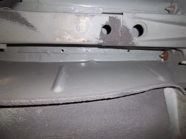
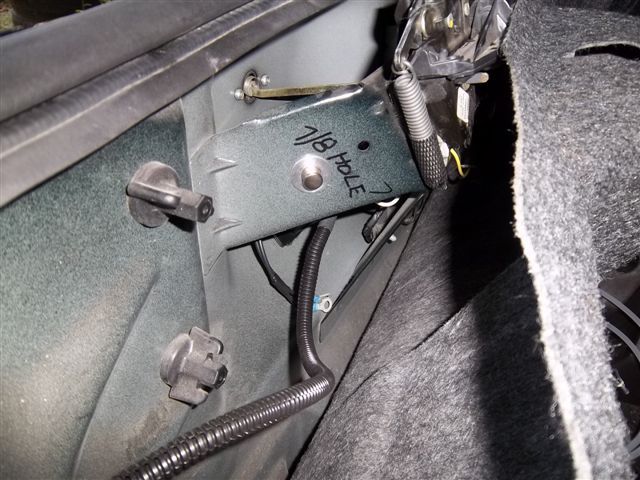
Marking frame rail for mounting bolts
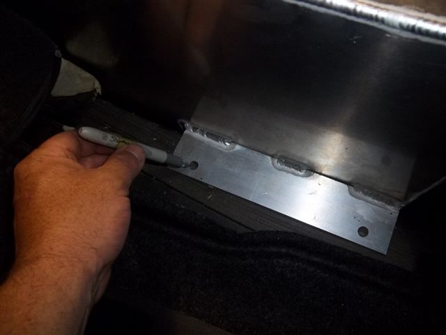
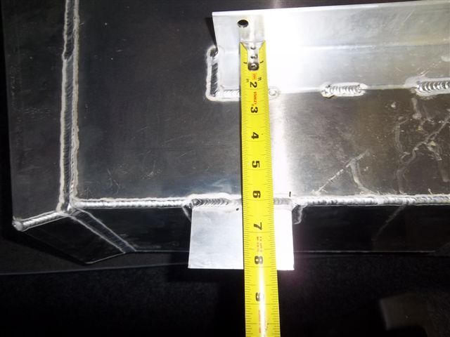
Notice the I/C tank mounting holes are drilled into the frame rail flange.
The metal is thickest here.
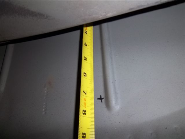
7" under the front mounting hole a mark is placed to the just to the left of the support rib.
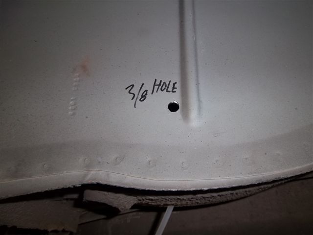
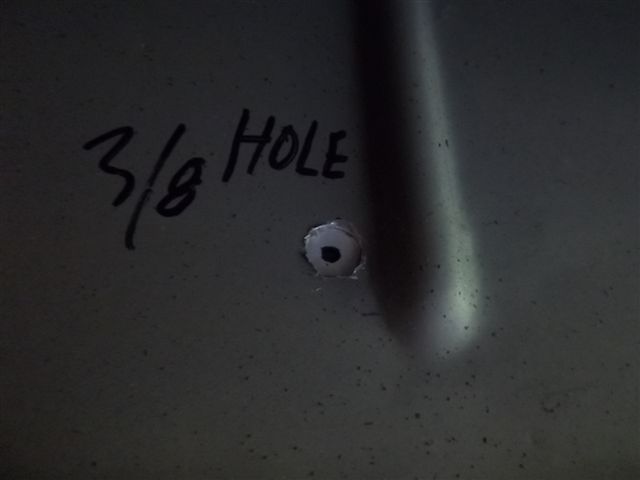
A 3/8 hole is drilled.
The tank is placed back in the car and the top mounting bolts are loosely installed.
A witness mark is placed on the lower I/C tank mounting tab.
Witness mark.
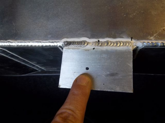
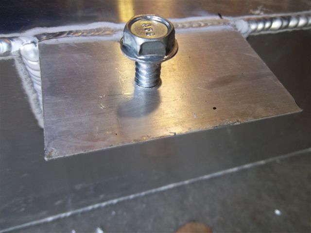
Hole it drilled
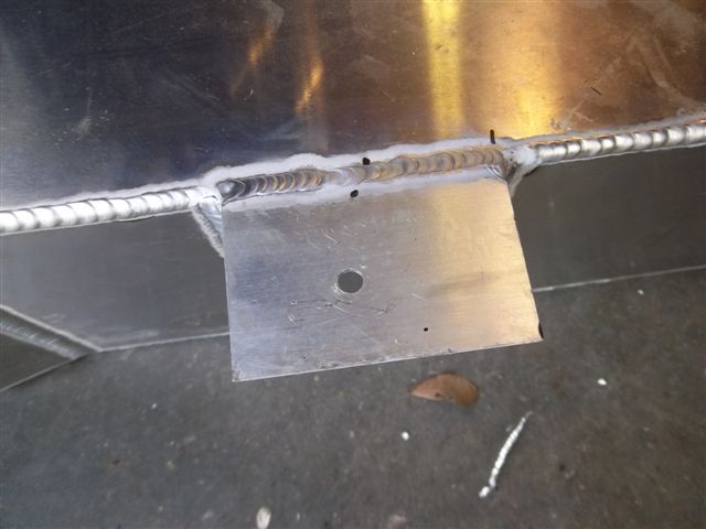
Thread forming bolt is screwed into hole to form threads making it easier to start the bolt
in the car
Notice the I/C tank mounting holes are drilled into the frame rail flange.
The metal is thickest here.
7" under the front mounting hole a mark is placed to the just to the left of the support rib.
A 3/8 hole is drilled.
The tank is placed back in the car and the top mounting bolts are loosely installed.
A witness mark is placed on the lower I/C tank mounting tab.
Witness mark.
Hole it drilled
Thread forming bolt is screwed into hole to form threads making it easier to start the bolt
in the car
Last edited by ModularTurbo; 06-03-2012 at 10:33 PM.

 06-03-2012, 08:18 PM
#19
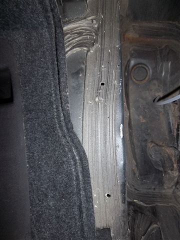
It is in the spare tire well.
You don't have to keep the water cold.
The water takes the heat off the intercooler and a heat exchanger takes the heat off the water.
The trick to a well engineered street A/W system is to have enough mass "water" to soak the heat and remove it from the intercooler.
This system is very complex compared to most systems.
This system holds 6.5 gallons.
06-04-2012, 09:20 PM
#20
Good afternoon guys.
When we set out to engineer an intercooling system for this kit we drew a line in the sand so to speak.
In no way shape or form were we going to influence the air flow coming through the AC condenser and the radiator.
By leaving the stock cooling system as GM engineered it, insured that the AC and engine cooling
would work as GM intended.
Beause the bumper covers on the 4th gen F-Body's are setup to draw air from the bottom of the bumper and not thru the front of it, we had only one option, air to water intercooling.
Once the decision was made, engineering a system that would work in a high HP daily driver was next.
After selecting the components that made up the system we were left with a decision, how to control
water flow.
Option 1, wire the pump and fan to a pressure switch and turn the system on only under boost.
The problem with this setup is the heat exchanger and the fan cannot take the heat out of the water
as fast as the intercooler can remove it from the boosted air.
If you are cruising around and get on it here and there sooner or later the water will become heat soaked.
The more water you can carry the more of a beating the system can take before heat soak is a problem.
Option 2, run the pump and fan all the time, this takes care of the heat soak problem but you have to ride around
listening to the fan and pump running constantly. Not to mention wear and tear on the pump and fan while putting the extra
amp load on the electrical system.
We came up with a solution that satisfies all the cons of both options 1 and 2.
The solution to the problem is to turn the pump and fan on when the system sees boost
and start a timer after the system is out of boost. The timer will continue to run the pump and heat
exchanger fan removing the heat from the water that the heat exchanger didn't get while under boost.
This prevents the system from becoming heat soaked.
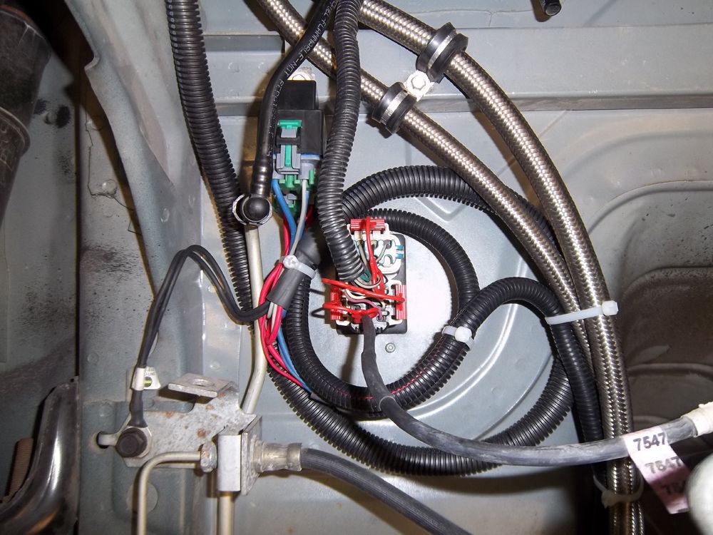
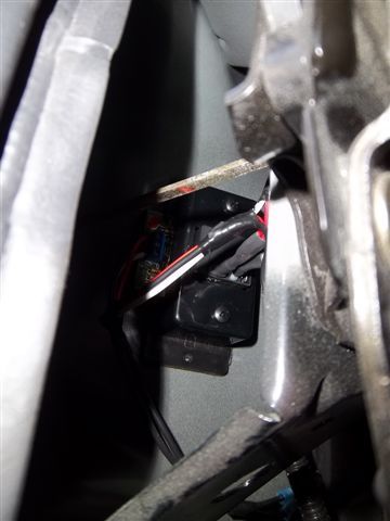
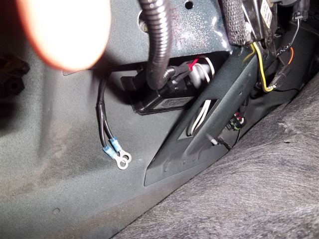
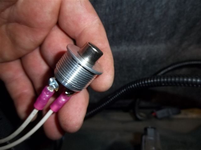
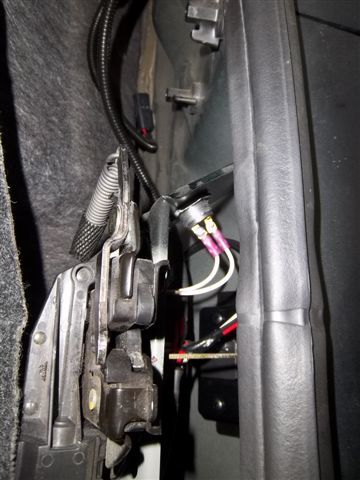
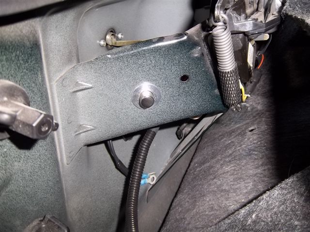
The little black box in the pic's is the relay/timer.
It is programmable from 30 sec-6 min's, we set it to run about 5 min's after boost is no longer present.
The button in the pic's is the manual override "run" button.
We integrated it into the system for a number of reasons.
1: You can manually test the system to ensure the pump and fan are working.
2: You can disconnect the return hose on the top of the tank and drain the tank by pumping it out.
This is handy if you are at the track and would like to put ice in the system.
You can pump out some of the water to make room for ice.
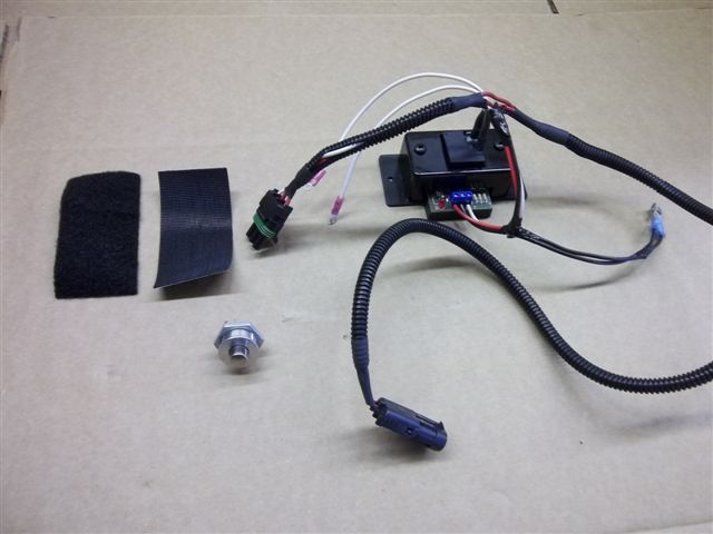
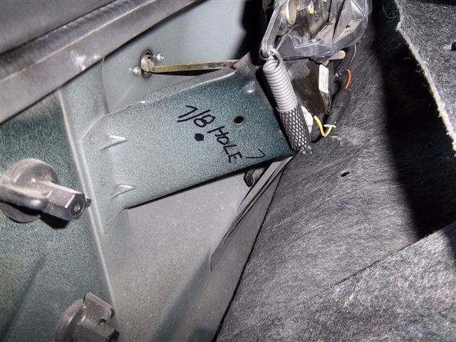
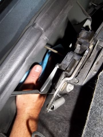
A paper towel was placed under the trunk latch to catch the chips from cutting the hole.
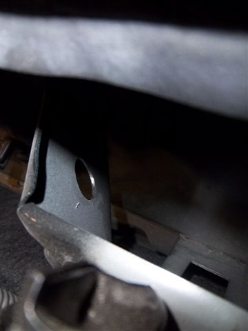
Notice the nasty burr left on the back of the hole.
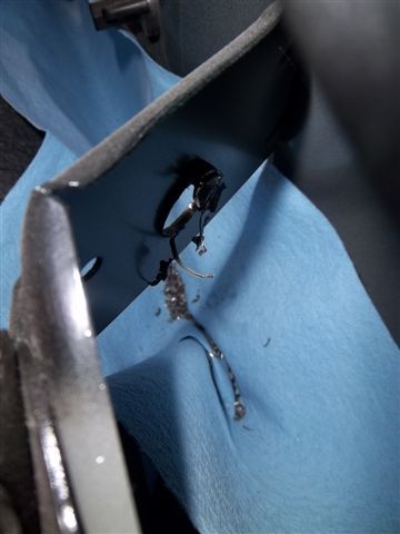
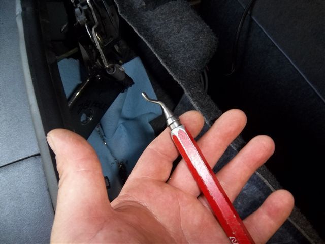
A de-burr tool makes short work of the burr.
A quick wipe down with a little lacquer thinner on a paper towel gets the surface ready for the
adhesive backed Velcro to mount the controller
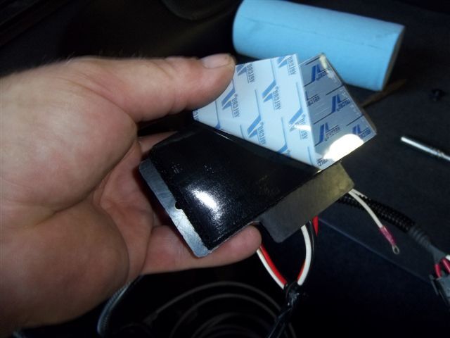
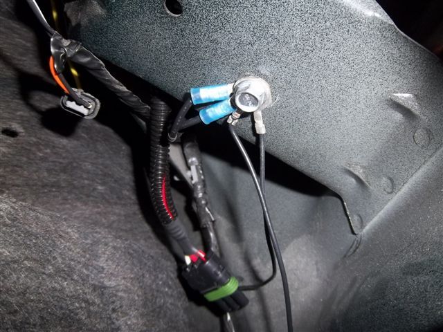
Cleaned up the Sharpie so it don't look like a 2 year old was there
When we set out to engineer an intercooling system for this kit we drew a line in the sand so to speak.
In no way shape or form were we going to influence the air flow coming through the AC condenser and the radiator.
By leaving the stock cooling system as GM engineered it, insured that the AC and engine cooling
would work as GM intended.
Beause the bumper covers on the 4th gen F-Body's are setup to draw air from the bottom of the bumper and not thru the front of it, we had only one option, air to water intercooling.
Once the decision was made, engineering a system that would work in a high HP daily driver was next.
After selecting the components that made up the system we were left with a decision, how to control
water flow.
Option 1, wire the pump and fan to a pressure switch and turn the system on only under boost.
The problem with this setup is the heat exchanger and the fan cannot take the heat out of the water
as fast as the intercooler can remove it from the boosted air.
If you are cruising around and get on it here and there sooner or later the water will become heat soaked.
The more water you can carry the more of a beating the system can take before heat soak is a problem.
Option 2, run the pump and fan all the time, this takes care of the heat soak problem but you have to ride around
listening to the fan and pump running constantly. Not to mention wear and tear on the pump and fan while putting the extra
amp load on the electrical system.
We came up with a solution that satisfies all the cons of both options 1 and 2.
The solution to the problem is to turn the pump and fan on when the system sees boost
and start a timer after the system is out of boost. The timer will continue to run the pump and heat
exchanger fan removing the heat from the water that the heat exchanger didn't get while under boost.
This prevents the system from becoming heat soaked.
The little black box in the pic's is the relay/timer.
It is programmable from 30 sec-6 min's, we set it to run about 5 min's after boost is no longer present.
The button in the pic's is the manual override "run" button.
We integrated it into the system for a number of reasons.
1: You can manually test the system to ensure the pump and fan are working.
2: You can disconnect the return hose on the top of the tank and drain the tank by pumping it out.
This is handy if you are at the track and would like to put ice in the system.
You can pump out some of the water to make room for ice.
A paper towel was placed under the trunk latch to catch the chips from cutting the hole.
Notice the nasty burr left on the back of the hole.
A de-burr tool makes short work of the burr.
A quick wipe down with a little lacquer thinner on a paper towel gets the surface ready for the
adhesive backed Velcro to mount the controller
Cleaned up the Sharpie so it don't look like a 2 year old was there
Last edited by ModularTurbo; 06-05-2012 at 06:09 PM.