How to Microsquirt fuel and spark your LSX swap (sloppy mechanics how to!) 8-10-13
 01-20-2013, 09:03 PM
#1


4-9-14 Updates EFI source and i have found some problems firing some coils, and found some universally compatable changing the resistors for 3.24k Ohm on the coils, i will update the other part of the document, ALSO we have found some wiring improvements.
Browns on each coil go to the CYLINDER HEAD. Not chassis ground, not sheet metal, not the MS grounds, nothing else but the cylinder head.
8-10-13 update EFI source also sells a plug and play wiring harness for this setup and the ecu already modded
** 5-8-13 update, mike @ EFI source is now offering to do the internal mods with the power and resistor before you buy the ecu! just remember to ask him when you order, he estimates 20 dollars extra on top of the sale price for pre-modded for LSX**
this covers the plug and play style microsquirt2, version 3 ecu for LSX gen3 24 tooth engines running batch fuel and waste spark all in the single box, using the stock crank position sensor, and stock coil near plug connector.
this runs great, and i used it on my fairmont and cranked out a very drivable and startable 611rwhp on 11psi of boost.
starting off with, and assuming you have a motor, sensors, intake and injectors, ready to go.
this might not be the best way, or the right way, but its the sloppy mechanics way and it works! ok...
buy yourself a Microsquirt and harness, and a 3 bar map and pigtail
the microsquirt comes with a prebuilt ECU in a small box and a ampseal 35pin connector and pigtail open end harness. you can get them in 8ft and 3ft.

i buy them from EFI source because they are about 30min south of my house!
I personally like to get the 8ft harness, because it can easily reach the farthest point, the drivers side coolant temp sensor and then still get the ecu in the car. and reach everything else, you just trim it down as you go.
you can call them to order it, get it on their website, or ebay store.
http://www.efisource.com/index.php
http://www.ebay.com/itm/Megasquirt-Microsquirt-V3-Version-3-EFI-Controller-w-8ft-harness-FREE-O2-sensor-/110945975502?pt=Race_Car_Parts&hash=item19d4e53cce&vxp=mtr
i also get the 3 bar map sensor and pigtail from them for 35 dollars
http://www.ebay.com/itm/GM-style-3-bar-map-sensor-w-pigtail-/121041299443?pt=Motors_Car_Truck_Parts_Accessories&vxp=mtr&hash=item1c2e9fa7f3
armed with these two items, you should know that you still have to modify the ECU itself to successfully run the crank sensor input and add two more ignition drivers to this ECU and harness setup. you can modify the harness to have these connections in it, but the back of the motherboard is easy to get to, and these mods are super easy to do!
you can flip it over and on the back there are four small screws that come out easily, and then when the back is off, youll see the 35 motherboard pins and actually a description screen printed on the back of the motherboard.
now to mod for LSX use you will need, 1x 1k ohm, 1/4 watt resistor, and
4-9-14* NOW using 3.24k OHM resistors instead of 4.7s
clip them short, and solder wires on the ends, about inc or inch and a half on each end and shrink wrap around them so they cant touch each other or short on the board pins, youll see in my picture below...
to modify the crank pickup circut to work correctly, you will need to attach the 1k ohm resistor from the 12v power connector pin to the VR1+ pickup input wire... you are basically bridging pin 1 to pin 32... as you can see in the picture the far right wire and you can see the heat shrink tight around the resistor. this is done so that the crank sensor can work like stock and be powered to generate the 12v wave the megasquirt ECU will be looking to decode!
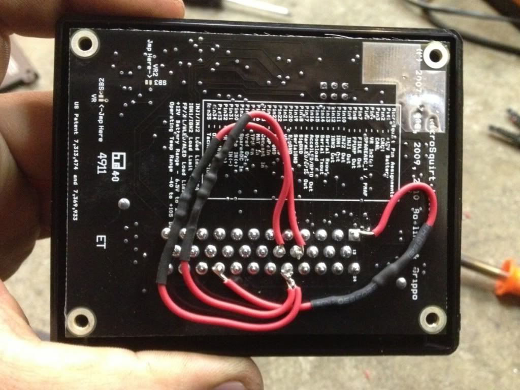
pin 1 is the upper right, and you can see it says pin 13 in the middle right and 24 in the bottom right, also you can see it actually tells you what every pin is, on the board, on the back of the motherboard...
do the same thing with small leads, and shrink wrapping the 3.24k ohm resistors.... those you are going to go from the 5v reference source, to ALED and WLED output wires... now we are doing this, because the microsquirt has two ignition outputs that fire a 5v signal, great for triggering LS coils, but, you will need 4, to fire in waste spark, not just the 2 included, passing the 5v to these LED output wires, gives them the ability to fire coils as trigger wires, just like the stock ign1 and ign2 trigger wires.
anyway you are going to connect both wire ends to pin 28 (5v reference) and then connect the other ends to pin 16 and 17 (ALED and WLED) as you can also see in the picture, its not that hard at all, i recommend adding a little solder to the end of the stripped wire, tinning it (meaning getting thin amount of solder on the wire already, and then adding a tiny bit more to the board pinout, then putting the tinned wire, on the pinout and pressing down with the iron and they will melt nicely together and then just make sure to hold it still till it cools and make sure its tight and wont pop off.
now that the Microsquirt ECU is setup nice and neat like this. you can then move on to wiring it up.
here is a wiring diagram that atomic6 wrote up
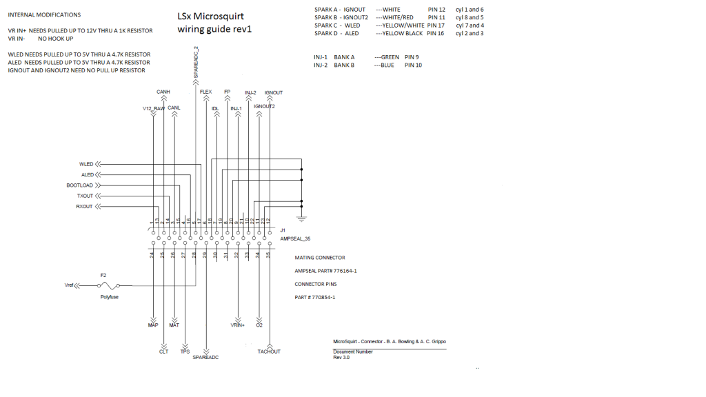
here it also lists, spark A B C and D outputs and what cyls they need to connect to.
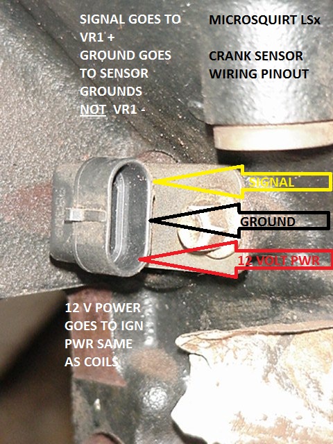
he also took this photo of the crank position sensor and wrote what connects to where
now building the harness on your own, you can get a plug from the V6 GM cars, that plugs right into this crank position sensor.
off a chevy blazer or buick 3800 etc, the 3 wire MAF plug will plug strait into the crank position on these blocks! pretty neat!
while you are in there you might as well cut out the IAT sensor and pigtail with it, because you can add that to your setup since the truck motors usually have the IAT built into the 5 wire MAF on them and you probably wont get it haha.
ok now on this picture, the signal wire, is going to goto the VR1 grey sheilded wire on the microsquirt, you will strip back the main grey and sheilding and expose a red and black wire, connect the signal wire on the crank position to the RED wire on the VR1 and pull back the ground wire and sheilding and tape them off good because if they touch the block or anything and ground or disrupt the crank signal you will have big problems, ask me how i know!
now next, you will connect that middle ground wire to the "sensor return ground wire" not just any old ground, or block or anything else, without this hooked up to the sensor return ground it will not see rpm accurately or work at all.
for the bottom plug, the red power wire, this wire needs to be connected to a 12v cranking power source much like the rest of the ecu, in fact when i wire these, i connect the ecu and this wire together, and power them with 3-5amp fuse, this works great for me, and makes it easier.
ok, from here you can wire this thing up like a regular megasquirt box, it is batch fire ignition so you run 10amp power wire up to your injectors from the ecu. area, thats how i do it anyway, and i split it to each injector bank. then you can connect one side of the injectors to the 12v power, and the other side of the injectors to the green or blue, whatever side you are using, as the injector driver wire from the ecu, then do the same thing to the other side, green on one side and blue on the other side.
next i also run another 15-20amp power feed up the harness and split that to the factory coil packs power connector wich is Pink! the black wire on the coil packs is the ground for them, you can combine this ground and even add it to the ground wires already in the microsquirt harness, wich are two big gauge black wires, and then ground them all together anywhere in the block or your chassis that works well.
4-9-14 **this is important so please pay attention. Browns on each coil go to the CYLINDER HEAD. Not chassis ground, not sheet metal, not the MS grounds, nothing else but the cylinder head. This obnoxious message has a strong likelihood of saving you hours or frustration and a shitload of broken engine parts so I recommend paying close attention to it
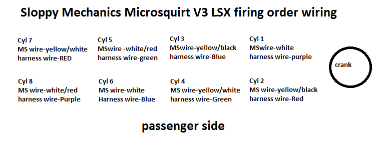
spark A - IGNout - white - Firing Cyl 1 and 6
spark B - IGNout 2 - white/red - Firing Cyl 5 and 8
spark C - WLED - yellow/white - Firing Cyl 7 and 4
spark D - ALED - yellow/black - Firing Cyl 3 and 2
also reference
ok, now that that is all done, you will also connect your temp sensors IAT and CLT, for this you just connect one side, usually the matching color side, and then the other to the sensor ground return wire, the white with a black stripe i believe.
for the TPS and MAP sensor you will need to split the 5v reference, and then connect it to the TPS (you can cut this from blazers and V6 buicks at the junkyard also!) the colors match up, i believe its
Blue - tps signal return to the ecu
grey - 5v reference from the ecu
black - sensor return ground
now if you got the map sensor from EFI source, it has the pinout sticker on top of the map, actually tells you what wires go where!
for reference though...
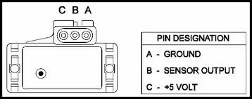
i usually hold it up like that, plug it into the map and then go left to right, wiring it, the map sensor return is a green and yellow stripe i believe, that will connect to B middle plug wire, and that is sensor output.
Browns on each coil go to the CYLINDER HEAD. Not chassis ground, not sheet metal, not the MS grounds, nothing else but the cylinder head.
8-10-13 update EFI source also sells a plug and play wiring harness for this setup and the ecu already modded
** 5-8-13 update, mike @ EFI source is now offering to do the internal mods with the power and resistor before you buy the ecu! just remember to ask him when you order, he estimates 20 dollars extra on top of the sale price for pre-modded for LSX**
this covers the plug and play style microsquirt2, version 3 ecu for LSX gen3 24 tooth engines running batch fuel and waste spark all in the single box, using the stock crank position sensor, and stock coil near plug connector.
this runs great, and i used it on my fairmont and cranked out a very drivable and startable 611rwhp on 11psi of boost.
starting off with, and assuming you have a motor, sensors, intake and injectors, ready to go.
this might not be the best way, or the right way, but its the sloppy mechanics way and it works! ok...
buy yourself a Microsquirt and harness, and a 3 bar map and pigtail
the microsquirt comes with a prebuilt ECU in a small box and a ampseal 35pin connector and pigtail open end harness. you can get them in 8ft and 3ft.
i buy them from EFI source because they are about 30min south of my house!
I personally like to get the 8ft harness, because it can easily reach the farthest point, the drivers side coolant temp sensor and then still get the ecu in the car. and reach everything else, you just trim it down as you go.
you can call them to order it, get it on their website, or ebay store.
http://www.efisource.com/index.php
http://www.ebay.com/itm/Megasquirt-Microsquirt-V3-Version-3-EFI-Controller-w-8ft-harness-FREE-O2-sensor-/110945975502?pt=Race_Car_Parts&hash=item19d4e53cce&vxp=mtr
i also get the 3 bar map sensor and pigtail from them for 35 dollars
http://www.ebay.com/itm/GM-style-3-bar-map-sensor-w-pigtail-/121041299443?pt=Motors_Car_Truck_Parts_Accessories&vxp=mtr&hash=item1c2e9fa7f3
armed with these two items, you should know that you still have to modify the ECU itself to successfully run the crank sensor input and add two more ignition drivers to this ECU and harness setup. you can modify the harness to have these connections in it, but the back of the motherboard is easy to get to, and these mods are super easy to do!
you can flip it over and on the back there are four small screws that come out easily, and then when the back is off, youll see the 35 motherboard pins and actually a description screen printed on the back of the motherboard.
now to mod for LSX use you will need, 1x 1k ohm, 1/4 watt resistor, and
4-9-14* NOW using 3.24k OHM resistors instead of 4.7s
clip them short, and solder wires on the ends, about inc or inch and a half on each end and shrink wrap around them so they cant touch each other or short on the board pins, youll see in my picture below...
to modify the crank pickup circut to work correctly, you will need to attach the 1k ohm resistor from the 12v power connector pin to the VR1+ pickup input wire... you are basically bridging pin 1 to pin 32... as you can see in the picture the far right wire and you can see the heat shrink tight around the resistor. this is done so that the crank sensor can work like stock and be powered to generate the 12v wave the megasquirt ECU will be looking to decode!
pin 1 is the upper right, and you can see it says pin 13 in the middle right and 24 in the bottom right, also you can see it actually tells you what every pin is, on the board, on the back of the motherboard...
do the same thing with small leads, and shrink wrapping the 3.24k ohm resistors.... those you are going to go from the 5v reference source, to ALED and WLED output wires... now we are doing this, because the microsquirt has two ignition outputs that fire a 5v signal, great for triggering LS coils, but, you will need 4, to fire in waste spark, not just the 2 included, passing the 5v to these LED output wires, gives them the ability to fire coils as trigger wires, just like the stock ign1 and ign2 trigger wires.
anyway you are going to connect both wire ends to pin 28 (5v reference) and then connect the other ends to pin 16 and 17 (ALED and WLED) as you can also see in the picture, its not that hard at all, i recommend adding a little solder to the end of the stripped wire, tinning it (meaning getting thin amount of solder on the wire already, and then adding a tiny bit more to the board pinout, then putting the tinned wire, on the pinout and pressing down with the iron and they will melt nicely together and then just make sure to hold it still till it cools and make sure its tight and wont pop off.
now that the Microsquirt ECU is setup nice and neat like this. you can then move on to wiring it up.
here is a wiring diagram that atomic6 wrote up
here it also lists, spark A B C and D outputs and what cyls they need to connect to.
he also took this photo of the crank position sensor and wrote what connects to where
now building the harness on your own, you can get a plug from the V6 GM cars, that plugs right into this crank position sensor.
off a chevy blazer or buick 3800 etc, the 3 wire MAF plug will plug strait into the crank position on these blocks! pretty neat!
while you are in there you might as well cut out the IAT sensor and pigtail with it, because you can add that to your setup since the truck motors usually have the IAT built into the 5 wire MAF on them and you probably wont get it haha.
ok now on this picture, the signal wire, is going to goto the VR1 grey sheilded wire on the microsquirt, you will strip back the main grey and sheilding and expose a red and black wire, connect the signal wire on the crank position to the RED wire on the VR1 and pull back the ground wire and sheilding and tape them off good because if they touch the block or anything and ground or disrupt the crank signal you will have big problems, ask me how i know!
now next, you will connect that middle ground wire to the "sensor return ground wire" not just any old ground, or block or anything else, without this hooked up to the sensor return ground it will not see rpm accurately or work at all.
for the bottom plug, the red power wire, this wire needs to be connected to a 12v cranking power source much like the rest of the ecu, in fact when i wire these, i connect the ecu and this wire together, and power them with 3-5amp fuse, this works great for me, and makes it easier.
ok, from here you can wire this thing up like a regular megasquirt box, it is batch fire ignition so you run 10amp power wire up to your injectors from the ecu. area, thats how i do it anyway, and i split it to each injector bank. then you can connect one side of the injectors to the 12v power, and the other side of the injectors to the green or blue, whatever side you are using, as the injector driver wire from the ecu, then do the same thing to the other side, green on one side and blue on the other side.
next i also run another 15-20amp power feed up the harness and split that to the factory coil packs power connector wich is Pink! the black wire on the coil packs is the ground for them, you can combine this ground and even add it to the ground wires already in the microsquirt harness, wich are two big gauge black wires, and then ground them all together anywhere in the block or your chassis that works well.
4-9-14 **this is important so please pay attention. Browns on each coil go to the CYLINDER HEAD. Not chassis ground, not sheet metal, not the MS grounds, nothing else but the cylinder head. This obnoxious message has a strong likelihood of saving you hours or frustration and a shitload of broken engine parts so I recommend paying close attention to it
spark A - IGNout - white - Firing Cyl 1 and 6
spark B - IGNout 2 - white/red - Firing Cyl 5 and 8
spark C - WLED - yellow/white - Firing Cyl 7 and 4
spark D - ALED - yellow/black - Firing Cyl 3 and 2
also reference
ok, now that that is all done, you will also connect your temp sensors IAT and CLT, for this you just connect one side, usually the matching color side, and then the other to the sensor ground return wire, the white with a black stripe i believe.
for the TPS and MAP sensor you will need to split the 5v reference, and then connect it to the TPS (you can cut this from blazers and V6 buicks at the junkyard also!) the colors match up, i believe its
Blue - tps signal return to the ecu
grey - 5v reference from the ecu
black - sensor return ground
now if you got the map sensor from EFI source, it has the pinout sticker on top of the map, actually tells you what wires go where!
for reference though...
i usually hold it up like that, plug it into the map and then go left to right, wiring it, the map sensor return is a green and yellow stripe i believe, that will connect to B middle plug wire, and that is sensor output.
Last edited by denmah; 04-09-2014 at 03:00 PM.
 01-20-2013, 09:03 PM
#2
ok from here the ecu is done and modded, you will need to load the newest MSextra firmware for the microsquirt to make it compatable with the LS1 wheel and waste spark configuration.
assuming you have a working com port, and the ecu and harness is ready to go, you can proceed by going to their website
http://www.msextra.com/downloads/ downloads page... and downloading the newest release
2/21/15 *update 3.3.3 is newest and fixed link for downloads page
flashing it with the firmware correctly does matter, i have flashed it other ways and been unable to start the car even though everyhing seemed ok! so this is important, and also easy haha but here is how to do it correctly...
once you download the firmware zip. you will extract the zip and have a folder of files like this

make sure TunerStudio or any other tuning software is closed!
also remove any fuses in the fuse panel for the coils, or the injectors, as during the flashing process it can fire them and possibly damage them!
Double click on ms2loader_win32.exe and follow along. choosing the correct com port for your device and all.
Debug level i choose 1 (default normal)
do you want to scan your com ports automatically i would hit no here and then choose your correct com port since this is the first time you will be flashing your ECU and you dont want to wast the time for it searching for the ecu.
when it says found firmware files, etc etcetc choose 1 for megasquirt 2 or choose 2 for microsquirt etc etc
you must choose microsquirt, make sure you get this right or you will also have trouble for obvious reasons haha
it will take you through steps of jumping the bootloader wire to a ground, and then powering on the ECU with the 12v connector, you can power the ecu and crank sensor together like i mentioned that wont hurt anything.
it will quickly connect and do a firmware flash, then ask you to power off, and then remove the boot loader wire again, make sure this cant re-ground when you leave it go. and it will ask you to power the ecu back on, and then hit next again, (again make sure your coil and injecto wires are not connected, or the fuses are pulled...
now it make sure you have a secure power connection and you are not just holding this **** to a battery because it will take like 4 min to flash the firmware lol and your fingers will be shot.
youll follow along with the instructions and power on the ecu and then it will wake it up and send a jumperless flash command and start flashing the ecu, when its all done. you can pull the power and hit enter and the firmware flashing box should dissapear.
next you can open tuner studio and download or use one of my downloaded base tunes.
power on the ECU and connect and upload the entire base tune when it says there is a difference, you choose to load the computer settings to the ECU.
this will give you a great base map and a whole bunch of settings setup for you already for LS engines. note that my tunes are for 3bar map and 80lb injectors, and i have another tune that is the stock 1 bar map on the back of the intake and stock injectors
hope this helps you out and shows that its not that hard!
let me know if you find any problems!
Micro2test bench tune (this fires the car on the stock map sensor, and stock injectors, i dont even know what size and its very rough i didnt even have a wideband when i fired it, but it did run and idle for about 2 minutes, and its all i got, and if you need it you can have it haha.
http://sloppymechanics.com/tunes/Micro2testbench.zip
fairmont E85 micro2 tune - http://sloppymechanics.com/tunes/Fai...Micro2_E85.zip
5.3/80lb siemens deka injectors, 50psi, 80mm turbo, 225/230 .618 114.5 lsa cam, ls1 intake, stock throttle, mix matched heads, 611rwhp on 12psi
Fairmont gasoline micro2 tune - http://sloppymechanics.com/tunes/Fai...2_gasoline.zip
5.3/80lb siemens deka injectors, 50psi, 80mm turbo, ls9 cam, ls1 intake, stock throttle, mix matched heads, 650rwhp on 24psi
Video i did today, showing how to power up and flash and test the ecu etc
let me know what you think!
assuming you have a working com port, and the ecu and harness is ready to go, you can proceed by going to their website
http://www.msextra.com/downloads/ downloads page... and downloading the newest release
2/21/15 *update 3.3.3 is newest and fixed link for downloads page
flashing it with the firmware correctly does matter, i have flashed it other ways and been unable to start the car even though everyhing seemed ok! so this is important, and also easy haha but here is how to do it correctly...
once you download the firmware zip. you will extract the zip and have a folder of files like this
make sure TunerStudio or any other tuning software is closed!
also remove any fuses in the fuse panel for the coils, or the injectors, as during the flashing process it can fire them and possibly damage them!
Double click on ms2loader_win32.exe and follow along. choosing the correct com port for your device and all.
Debug level i choose 1 (default normal)
do you want to scan your com ports automatically i would hit no here and then choose your correct com port since this is the first time you will be flashing your ECU and you dont want to wast the time for it searching for the ecu.
when it says found firmware files, etc etcetc choose 1 for megasquirt 2 or choose 2 for microsquirt etc etc
you must choose microsquirt, make sure you get this right or you will also have trouble for obvious reasons haha
it will take you through steps of jumping the bootloader wire to a ground, and then powering on the ECU with the 12v connector, you can power the ecu and crank sensor together like i mentioned that wont hurt anything.
it will quickly connect and do a firmware flash, then ask you to power off, and then remove the boot loader wire again, make sure this cant re-ground when you leave it go. and it will ask you to power the ecu back on, and then hit next again, (again make sure your coil and injecto wires are not connected, or the fuses are pulled...
now it make sure you have a secure power connection and you are not just holding this **** to a battery because it will take like 4 min to flash the firmware lol and your fingers will be shot.
youll follow along with the instructions and power on the ecu and then it will wake it up and send a jumperless flash command and start flashing the ecu, when its all done. you can pull the power and hit enter and the firmware flashing box should dissapear.
next you can open tuner studio and download or use one of my downloaded base tunes.
power on the ECU and connect and upload the entire base tune when it says there is a difference, you choose to load the computer settings to the ECU.
this will give you a great base map and a whole bunch of settings setup for you already for LS engines. note that my tunes are for 3bar map and 80lb injectors, and i have another tune that is the stock 1 bar map on the back of the intake and stock injectors
hope this helps you out and shows that its not that hard!
let me know if you find any problems!
Micro2test bench tune (this fires the car on the stock map sensor, and stock injectors, i dont even know what size and its very rough i didnt even have a wideband when i fired it, but it did run and idle for about 2 minutes, and its all i got, and if you need it you can have it haha.
http://sloppymechanics.com/tunes/Micro2testbench.zip
fairmont E85 micro2 tune - http://sloppymechanics.com/tunes/Fai...Micro2_E85.zip
5.3/80lb siemens deka injectors, 50psi, 80mm turbo, 225/230 .618 114.5 lsa cam, ls1 intake, stock throttle, mix matched heads, 611rwhp on 12psi
Fairmont gasoline micro2 tune - http://sloppymechanics.com/tunes/Fai...2_gasoline.zip
5.3/80lb siemens deka injectors, 50psi, 80mm turbo, ls9 cam, ls1 intake, stock throttle, mix matched heads, 650rwhp on 24psi
Video i did today, showing how to power up and flash and test the ecu etc
Last edited by denmah; 02-21-2015 at 07:54 PM.
01-20-2013, 10:15 PM
#5
i think you just change the settings from LS1 in the ignition settings and put in all the info for 58 tooth and you ahve to wire up the cam position sensor then i think too... not totally sure.
i think the 58 is a -2 tooth and you might be able to set that up waste spark without the cam sensor also...
i know it can be done, im not sure on the specifics, sorry haha
i think the 58 is a -2 tooth and you might be able to set that up waste spark without the cam sensor also...
i know it can be done, im not sure on the specifics, sorry haha
01-20-2013, 10:29 PM
#6
TECH Apprentice

Only a couple of differences, but can definately run one.
The 58 tooth engines would be different in the way the software is setup(ignition constants),and possible the crank sensor pull-up. The 58 tooth sensor(grey) is slightly different than the 24 tooth sensor(black)
I haven't tried it yet, maybe Matt will get one in something and try it.Or even on that nifty new stand he has!!!
The change in the ignition settings would be to tell the Microsquirt software to decode the 58 tooth wheel instead of the LS1 wheel(24 tooth), pretty easy to use the same computer if you change to the newer,stronger rods version Gen IV at some point. I.E. changing to an LY6 from an LQ4 to get the better rods and heads would not require a different ECM.
BTW: good write up Matt.
Last edited by atomic 6; 01-25-2013 at 02:03 AM.

Trending Topics
01-20-2013, 11:46 PM
#8
Staging Lane
iTrader: (1)

Join Date: Jul 2009
Location: Springfield,Ohio
Posts: 60
Likes: 0
Received 0 Likes
on
0 Posts
Man youre the greatest!!! This may be a dumb question but is it possible to maintain ac using microsquirt due to extra load from the compressor drawing on idle? I thought you were going to sell these already built?
01-21-2013, 02:16 PM
#9
currently the way i run this there is no way to do closed loop idle control, if you want AC and stuff like that i would say you might want to goto a more sophisticated unit.
but this thing makes a cheap race car with a manual or th400 style manually operated automatic.
but this thing makes a cheap race car with a manual or th400 style manually operated automatic.
01-21-2013, 03:02 PM
#10


Matt,The amount of time and effort you put in to help out people blows me away. I know for me something like this is huge because I have been messing with cars for 30 years but I suck at anything that has to do with a computer.
Thanks for all you do.
Thanks for all you do.
 01-21-2013, 08:44 PM
#15
TECH Regular
iTrader: (2)
Join Date: Dec 2009
Location: Austin Texas
Posts: 414
Likes: 0
Received 0 Likes
on
0 Posts
You know this helps me!!!! This is the "Microsquirt for Dummies" / Cliff Notes that I need to make sure I do my Microsquirt correctly...
If anyone has any additional info for the 58x wheel PLEASE post it up. Im hoping it will work the same as the 24x and just correcting it to 60-2 in TunerStudio.
Also if anyone has a "stock" 5.3 base tune that would be a great help.
If anyone has any additional info for the 58x wheel PLEASE post it up. Im hoping it will work the same as the 24x and just correcting it to 60-2 in TunerStudio.
Also if anyone has a "stock" 5.3 base tune that would be a great help.
01-21-2013, 08:44 PM
#16
TECH Regular
iTrader: (2)
Join Date: Dec 2009
Location: Austin Texas
Posts: 414
Likes: 0
Received 0 Likes
on
0 Posts
You know this helps me!!!! This is the "Microsquirt for Dummies" / Cliff Notes that I need to make sure I do my Microsquirt correctly...
If anyone has any additional info for the 58x wheel PLEASE post it up. Im hoping it will work the same as the 24x and just correcting it to 60-2 in TunerStudio.
Also if anyone has a "stock" 5.3 base tune that would be a great help.
If anyone has any additional info for the 58x wheel PLEASE post it up. Im hoping it will work the same as the 24x and just correcting it to 60-2 in TunerStudio.
Also if anyone has a "stock" 5.3 base tune that would be a great help.
01-22-2013, 12:09 PM
#20
FIDLE - is fast idle
i believe it sends a ground output signal, only can support 1 amp or less though you would have to look it up.
i have used it on the MS1 you can use settings in the ecu then to open the fast idle solenoid to create a air leak to raise the idle, then at a set temp like the fans, it will turn off the output, like 110f it will close the leak and go back to your other set idle, its how people used to idle up cars i think older BMWs and whatnot have a Fast Idle Valve.