When you click on links to various merchants on this site and make a purchase, this can result in this site earning a commission. Affiliate programs and affiliations include, but are not limited to, the eBay Partner Network.
Has anyone have any real world experiences of how much extra boost (with the same WG Spring) you can achieve with a 4 port Boost Solenoid over a 3 port ?
Also can you say which WG you used to achieve it, as I'm pulling the trigger on the Turbos and need to make up my mind which gates to buy..
Yup zero... There is no advantage in max boost between the two. The most boost you can have is with the lower port blocked and all your manifold going to the top port of the WG. You can easily do that with a 3 port or a 4 port. I use a 3 port on my setup, plumbed like so with a very tiny bleed hole in the top port.
Yup zero... There is no advantage in max boost between the two. The most boost you can have is with the lower port blocked and all your manifold going to the top port of the WG. You can easily do that with a 3 port or a 4 port. I use a 3 port on my setup, plumbed like so with a very tiny bleed hole in the top port.
Force, do you run it progressively through the ecu (meaning can you give it various duty cycles for different boost levels) or is it on an "on/off" switch.
So by adding pressure to the close side of the diaphragm, this doesn't allow you to bleed off any more and get higher boost pressure ?? So why have one at all...
I'm confused
Force, do you run it progressively through the ecu (meaning can you give it various duty cycles for different boost levels) or is it on an "on/off" switch.
I run progressive boost by speed on the street and ramp in boost over time at the T-brake release at teh track.
Originally Posted by lm1clive
So by adding pressure to the close side of the diaphragm, this doesn't allow you to bleed off any more and get higher boost pressure ?? So why have one at all...
I'm confused
Not sure what you mean by close side? Usually referred to as top/bottom ports on the WG?
The way I have my 3-port setup above...
It will slowly phase out the port going to the bottom of the WG dependant on duty cycle. So at 100% DC all the pressure is going to the top port on the WG helping keep it closed. I currently can get the boost down to about 8lbs at my lowest setting (0%DC or no power to solenoid) which allows boost straight into the solenoid and directly to the bottom port with zero boost going to the top port. 54% DC nets me about 17-18lbs. I'm sure I can run 25+ at 100% DC.
Has anyone have any real world experiences of how much extra boost (with the same WG Spring) you can achieve with a 4 port Boost Solenoid over a 3 port ?
Also can you say which WG you used to achieve it, as I'm pulling the trigger on the Turbos and need to make up my mind which gates to buy..
Thanks in advance BTW
Depends entirely how you configure them as ForceFed says
Ok, so if I have say a 6psi mechanical spring on the gate whats the most boost I could get by using any of the solenoid routing methods ( Obviously I'll have full control of the Coil PWM from 0 - 100% duty cycle)
I just saw a video of a well know shop saying that I won't get anymore boost than double the spring pressure, as the gate will tend to open above that...
What I would like ( the reason why I'm asking ) is the ability to alter the boost level from 6 to 20 psi all via my ECU and a multi-function switch on the dash.... is it possible without a Pressurized C02 bottle ??
The well known shop doesn't have a clue then.
If you stop signal to the bottom of the gate completely you'll usually see around double the spring pressure. Then if you start applying pressure to the top of the WG you'll see more than double. Done it many times. I ran 9lbs with a line directly to my bottom port. Blocked the bottom signal completely I saw 19ish. Then started applying pressure to the top gate and I'd see 26lbs. Even hit 30 a couple times on accident.
It's impossible to say what your max boost level will be. The spring is just an estimate. The WG chamber size, valve face area, and exhaust back pressure all play a roll.
Ok, so if I have say a 6psi mechanical spring on the gate whats the most boost I could get by using any of the solenoid routing methods ( Obviously I'll have full control of the Coil PWM from 0 - 100% duty cycle)
I just saw a video of a well know shop saying that I won't get anymore boost than double the spring pressure, as the gate will tend to open above that...
What I would like ( the reason why I'm asking ) is the ability to alter the boost level from 6 to 20 psi all via my ECU and a multi-function switch on the dash.... is it possible without a Pressurized C02 bottle ??
In simple terms, there is no generic answer.
But unless there are some major inefficiencies with your setup I would see no problems at all running a range from 6-20psi using only 3 port solenoids and boost pressure as the control reference.
I've the base 7psi or so springs in my Precision gates and have run from that 7psi through as much as 28psi so far and I know I could push it a little harder if needed.
If you did go to CO2 or a high pressure air source, that would give you an even wider range but I really do not think it is necessary.
Ive always used this style of plumbing, but after looking at Forcfed's post, im starting to see why his setup is better.
So i will typically run 100% duty cycle in the controller basically until a few hundred rpm before it actually makes boost to help with spool, but the diagram below that really doesnt do anything because the bottom of the gate is always getting any pressure made by the source.
Yup zero... There is no advantage in max boost between the two. The most boost you can have is with the lower port blocked and all your manifold going to the top port of the WG. You can easily do that with a 3 port or a 4 port. I use a 3 port on my setup, plumbed like so with a very tiny bleed hole in the top port.
Can you elaborate on the size and placement of your bleed hole?
Believe I used a .030 carb jet bit. I'm using push to connect fittings so I just drilled the nylon line just before it enters the top WG port. It acts as a vent so pressure isn't trapped on the top of the gate after a pull. You can drill the fittings, or even the top of the WG dome itself.
I'm actually using 2 wastegates on my setup and one 3-port solenoid to operate both. It will just add complexity/confusion if I post up my plumbing.
Can see the hole pretty clearly here. I think I could go smaller.
Last edited by Forcefed86; 01-17-2016 at 11:05 AM.
But the 4 port seems to change the amount of crossover between the ports?
Which is exactly what it does in that configuration. You dont need to use it in that configuration, but it's how it would work if you did.
And the valve itself is never stationary other than at 0% duty or 100% duty ( although strictly speaking not a lot happens until around 10% duty anyway )
So it's always shuffling air to different locations depending on duty applied to it.
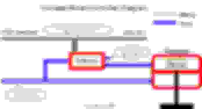
In your top diagram you've configured it for maximum boost at 0% duty and minimum boost at 100% duty, which isnt a typical configuration as most like a higher duty to offer represent more boost.
Also the way you've it shown should power be lost to the solenoid, should it fail etc...you're always in a maximum boost scenario. So not really a good way to do it.
Which is exactly the same as how the 3 port solenoid works anyway.
This is not the reverse configuration. I don't think you looked at the top picture closely. Notice the last line of text: Solenoid "ON"/Energized. i.e. in the off state or 0% duty it would put pressure to the bottom port and have the top port going to atmosphere.
Like I said, I'm interested in seeing a shot or schematic of the inside on a 4 port solenoid to understand how it manages to cross the flow over from one set of ports to another.
 01-16-2016, 12:40 PM