When you click on links to various merchants on this site and make a purchase, this can result in this site earning a commission. Affiliate programs and affiliations include, but are not limited to, the eBay Partner Network.
Andrew, you video was very informative. It's good to collect more info about other modules out there and the understand how each work. I saw in the Holly document in your video that two of the ports support the P- scheme which is what I called sink to ground earlier. That's good to know.
So that means that the holly dominator can drive these both the C6 module and the Mazda fan modlules as well, and most likely many others. Also if someone does not have a holly, the arduino can easily be set up to change from the default frequency to 128Hx required by the C6 module.
Based on your video and what I've learned about the mazda module, using a holly dominator and a mazda module, one might set the starting pwm duty at 24 percent and max at 100 percent.
The sound of your fan in the video sounded like it it wasn't at 128hz to me. So is the vette module converting the frequency from 128hz to something higher? Does the vette module ramp the speed up?
One of the nice features about the Mazda is that even if you put it on 100%, it slowly ramps up the speed so the inrush current is low.
There was a discussion a few years back, on the Holley support forum, about how the C6 controller works. Most of it was over my head, but I do recall someone stating that the output was something like 19kHz. The C6 controller does ramp the fan speed slowly, so there is no big inrush current. I never hear my fan and it rarely goes above 50%. I have the duty cycle displayed on my 7" Holley dash. I have the fan speed configured based on coolant temps and vehicle speed. One of my other friends uses the same setup, but with A/C. His is configured so that when the A/C is ON, the fan goes 50% (this can be any number), regardless of engine temperature. Then, as coolant temp rises, so will fan speed.
The Dominator has something like 64 user defined outputs (and 64 inputs) and they can each be configured in a variety of ways (+, -, PWM+, PWM-..etc..). The diagram in the video was only for the 554-400 I/O harness, which is 4 inputs and 4 outputs. The rest have to be pinned directly at the ECU.
I have a project for you. See if you can design a closed loop feedback control for a fuel pump based on actual fuel pressure. In other words, make it just like closed loop for AFR. You would input the desired fuel pressure, then your magic pixie dust scrambler adjusts duty cycle to maintain said fuel pressure. I think one of the problems that you will have is the that these fan controller are slow acting. This is good for cooling fans, but not so good for a fuel pump. A fuel pump will need to react much quicker to changes in fuel pressure and adjust duty cycle accordingly.
I hope all of that made sense...LOL
Also, new GM car fans have the fan controller built into them.
In the 5th picture you can see the yazaki connector with two 9.5 mm terminals and a small terminal for the PWM signal. Incidentally, do you know where I can source Yazaki connector parts? Mouser does not have them. I bet the Mazda connectors are also Yazaki.
Andrew
Last edited by Project GatTagO; 09-17-2018 at 02:47 PM.
I have a project for you. See if you can design a closed loop feedback control for a fuel pump based on actual fuel pressure. In other words, make it just like closed loop for AFR. You would input the desired fuel pressure, then your magic pixie dust scrambler adjusts duty cycle to maintain said fuel pressure. I think one of the problems that you will have is the that these fan controller are slow acting. This is good for cooling fans, but not so good for a fuel pump. A fuel pump will need to react much quicker to changes in fuel pressure and adjust duty cycle accordingly.
Andrew
As it turns out, I was designing my own PWM drivers for the fuel pump when I stumbled on these modules. A full closed loop Fuel system is a definitely more of a challenge than a fan driver. The magic pixie dust is called PID, an algorithm for closed loop feedback that is tune able. Tuning PIDs is an art in itself. I'm not going closed loop at this time, I just run the pump at a percent more juice than it needs based on both boost and RPM and let the fuel pressure regulator take care of the fine details. However, what I am thinking about for the fuel system is a variable voltage booster supply that can feed the fuel pump with lets say 10 - 18 volts based on boost and RPM. Want to see what max HP i can get out of the Walbro 450. Maybe someday when I have time, I'll start a thread for that.
Originally Posted by Project GatTagO
do you know where I can source Yazaki connector parts? Mouser does not have them. I bet the Mazda connectors are also Yazaki.
Andrew
You can get fan controllers from Jeeps for extremely cheap as well. They're used often with megasquirt to PWM a fuel pump.
Joe, Do you have and detail specs on how they work, part numbers? You're always a good resource for information. It would be good to have all the info in one place.
My silverado fans run on standard relays using the oem schematic and they pull a ton of current at power on. it would be nice to smooth that out.
Here is a 3 speed fans, soft start, adjustable low speed, no PCM, holly or arduino required, just 2 relays. Works for 1 or 2 fans.
If you can turn two relays on and off, you can do this. The potentiometer lets you adjust the low speed setting. If you just want about half speed, then replace the potentiometer with a 4.7k resistor.
top relay is the on/off. Bottom relay is the High/LOW relay High = on, Low =off
You wire the coil side of the relays anyway you need to.
Need 5 speeds? Guess how many relays? it's not a gimme.
Last edited by LSswap; 09-17-2018 at 08:20 PM.
Reason: more info
Since you were talking about fan speed, I wanted to clarify something with respect to the Holley. The pwm table is user defined, but also keep in mind that the ECU will interpolate values between the cells. For instance, I think I have the fan start off at 10% @ 195 degrees. So as the temperature approaches 195, the fan will start to spin up gradually. If the temperature is stable, the fan speed will hold steady and if the temp starts moving down, so does the fan speed.
I have used the C6 Corvette fan controller on my Cougar for years with the Holley Dominator. The C6 controller is much bigger and is about $100, although the Ford Fusions used the same controller and those can be found cheap in the junk yard. Just as an FYI, since you like to tinker, the C6 controller works with a fixed 128Hz input.
It's a nice piece. I picked one up at the pick and pull for $10 with the connectors. I ran it through some tests. Here's what I saw:
It also has a internal pullup on the signal wire, but unlike the mazda module the pullup is to 12 volts.
Actually the input PWM frequency input is not that critical. I ran it from 70hz to 5000hz and it pretty much behaved the same across the board.
The output frequency appeared to be about 19,000hz, so the fans(s) runs quietly.
I also has the step function where it ramps the fan speed up to full speed in increments.
The PWM signal input can work both with a 0 to 5 volt signal, typically driven directly by a microprocessor or by a sink to ground like in the Holley Dominator P- configuration.
I don't believe it can be controlled by a DC voltage, only by a PWM.
It has an interesting input control strategy. If you compare the PWM inputs between the mazda and the C6 vette/ford unit, the main takeaway is that the control signal duty is sort of opposite. On the C6 unit, maximum fan speed is when the PWM is grounded for about 95% of the duty cycle. Minimum speed is when it's grounded about 10% of the duty cycle. Below 10% the fans shuts off.
Here is something I believe is very important for those if you who don't want your ride to go up in a steaming pile of poo. Listen to Andrew's video and set the Holley max PWM no higher than the 90% he suggested. The reason for this is when the PWM is over about 95% or higher to the C6 module, the fan will shut off. That means that your engine will keep getting hotter and the cooling fan will be off. It seems counter intuitive that since 90% is a faster fan than 80%, so why wouldn't 98% or 100% be faster than 90%?. It's just the way the C6/Ford module is. Unlike school, a 98 or 100 is a hot fail here.
Just for comparison, maximum speed on the Mazda module is when the Holley style sink PWM is grounded for the least percentage in the duty cycle, or 0%. With the Mazda and Holley P- port, 76% would be the slowest speed and 0% would be the fastest speed and between 75% (or so) to 100% would be off. This is assuming the same P- port and other settings Andrew had.
I don't have a Holley, I'd appreciate someone testing my theory out.
I have a Dominator. and I wouldn't mind playing around with one of the Mazda units. Where can I score one for cheap? Not a huge fan of buying stuff on eBay...Amazon?
I have a Dominator. and I wouldn't mind playing around with one of the Mazda units. Where can I score one for cheap? Not a huge fan of buying stuff on eBay...Amazon?
I also have a Pull-a-Part not too far from me.
Andrew
I scored a complete mazda unit with connectors and I scored a complete C6/Ford unit with connectors each $10 at JY
If you want to play with either or both, I can ship you either or both and then you can return them when finished. PM me if you want to do that.
Back in the day, when you wanted to diagnose a problem and understand what is really happening inside those wires you needed one of these, and most hobbyists could not afford one.
I used to drag one like this into the garage. Things have changed.
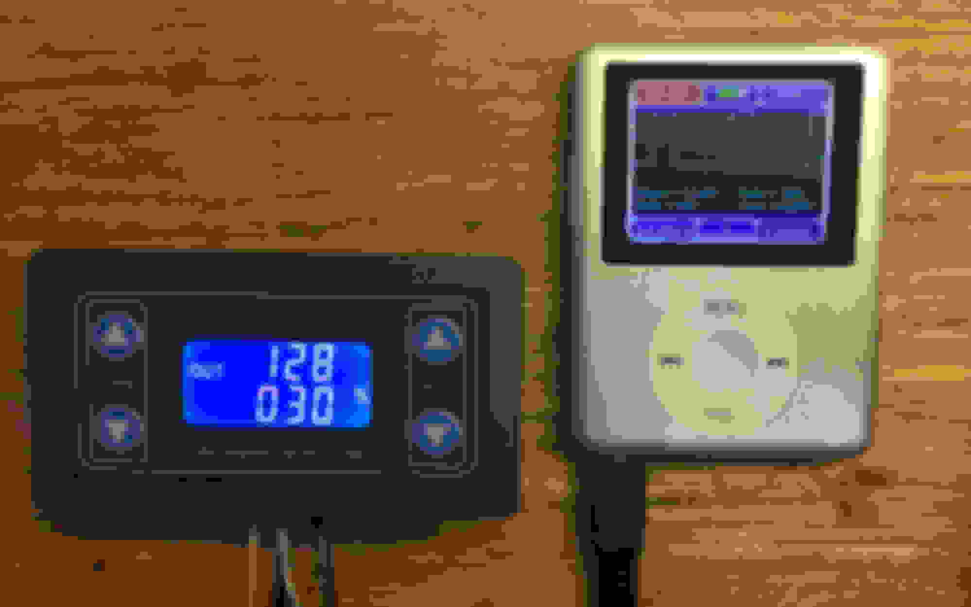
The tiny scope in the middle of the picture is a DSO168 portable digital storage scope. It's $45 shipped on Ebay. I just got one and I'm amazed how good it is for the price. Not only does it show you the waveform, but it calculated the duty% and the frequency, peak voltage, min voltage and average voltage among other things, Has it's own built in rechargeable battery and comes with a probe and charging cord. Instructions could have been better, but I got the hang of it after playing for a while.
The meter on the right is just for size reference.
The gizmo on the left is a PWM generator. The number on top is the frequency it's putting out and the one on the bottom is the duty cycle. It's $7 with shipping.
I tested the fan modules previously with my old stone age scope and a bunch of software in a processor board. I'm using these from now on, much easier.
In addition to looking at things like fan PWM, the scope can be used to look at cam trigger, crank trigger or any digital or analog signal. It can also be used in place of a voltmeter since in addition to showing the voltage, it calculates it shows the numerical value like a multimeter.
Here is the PWM generator and Scope actually running the C6 fan controller.
Sorta. But smaller and with a mini usb charging port, not an apple port. Sampling rate is 100 Million per second. I don't think the Ipod had anywhere near that horsepower.
Back in the day, when you wanted to diagnose a problem and understand what is really happening inside those wires you needed one of these, and most hobbyists could not afford one.
I used to drag one like this into the garage. Things have changed.
I used one of these to diagnose a misfire on a 599 GTO a few months ago! The shop I work at has not scooped one of the nicer Flukes unfortunately. I will hopefully be using this thread to make the fan controller for my Subaru.
As DIY projects go, the wiring is extremely simple.
I have tested this combo with a C6 style fan controller module on my bench.
The switch completely disconnects the PWM generator from the car so when the switch is on, the PWM generator controls the fan. When it's off, the ECM controls the fan as normal .
Here's a wiring diagram. I modified a C6 Z06 diagram I found.
The circuit is all low power, in the several milliamps range, so all the wires can be signal wires.
The SPD CTRL wire between the ECM and the Fan Control Module needs to be cut (anywhere along the length) and connected to the switch. Make sure you connect the side going to the Fan Control Module to the center pole of the switch.
If you connect the 12Volts to an Ignition 12 volt source, the override only works with the ignition on. If you connect it to the battery, the override should work even when the car is off, so it's up to you to remember to turn the override off once it all cooled off, or risk a dead battery.
The switch doesn't have to be big and ugly like in the picture. Any small Dual Pole Dual Throw (DPDT) switch can be used.
Basically, the switch is changing the source of the PWM signal that the Fan Module sees from one PWM source to the other. It also turns the power on to the module so will know when the override is in control.
Shouldn't be too hard to apply the concept in the diagram to ECM or Holley or AEM controlled C6 modules.
 09-17-2018, 01:54 PM


 sQAAOSwMudblh4p:rk:13:pf:0

