When you click on links to various merchants on this site and make a purchase, this can result in this site earning a commission. Affiliate programs and affiliations include, but are not limited to, the eBay Partner Network.
(*Lordy it's been a LONG time since I updated or even looked at this thread, but since this virus pandemic, I guess I got alot of time on my hands, so even though I'm a bit burnt out on the whole car thing, I thought I'd at least update in hopes it'll help others. "Latest" dyno is above, and it was around 2017 as I recall.)
This build of mine has been going on for what seems like a very long time. I guess now that I can somewhat see the light at the end of the tunnel, this would be a good time to post my route to achieving some sort of end that others may find informative. So bear with me as I post this freaking novel:
This all started with some �-mile and �-mile racing. The �-mile stuff was killing parts (aftermarket CV joint), and the �-mile stuff was demanding a lot more power than a cammed stock LS3 block could deliver and of course, nitrous was a bit hard on the pistons (mainly the tight ring gap, otherwise the stock LS3 parts are actually pretty decent).
In 2011, about a year after buying ‘Mo, a 2010 2SS Camaro, Mike Norris put a custom Comp cam in the motor, and it did well, about 470 rwhp on motor, 580’ish on nitrous. Then in 2012 the motor developed a squeaking sound that I thought was a power steering pump, but after pulling the valley cover, I could see the tell tale signs of cam lobe wear and pitting. So I decided to pull the motor and rebuild it. Lifters were almost all shot too, btw. Interestingly, I always used really good oil, basically Amsoil synthetics for the most part, and towards the end, even some MoS2 additive, and I wonder how much the Amsoil’s ZDDP and the MoS2 helped mask a lot of the cam’s problems. I’ve certainly seen others with far less cam lobe wear pull their motors apart far sooner. In my case, over half my lobes and lifters were pitted, and yet, even the week before I pulled the motor, it was basically a mechanically quiet motor with no real hint of problems.
THE PLAN:
1. Build a 416 stroker, with mild compression (10:1) for a future centrifugal supercharger (Procharger F1C).
2. Build in moderately high RPM capability to both take advantage of a Holley Hi-Ram intake as well as delay the need for 5th gear in a �-mile race.
3. Build a fuel system to support the above.
4. Build a �-mile friendly rear end that is as bulletproof as possible, and switch to a 1-piece driveshaft.
5. Reconfigure the single stage wet nitrous 92mm system to dual stage dry nitrous 102mm system.
The thinking here is that centrifugals are a bit safer and easier to tune (I do 90% of my own tuning), easier to race with their gradual torque build, and of course, there’s a wider variety of them compared to sit-on-top blowers. Moreover, with their higher engine compression requirements (10.x vs 9.x) , a streetable normally aspirated motor can be run while waiting for funds for the centrifugal.
Phase 1
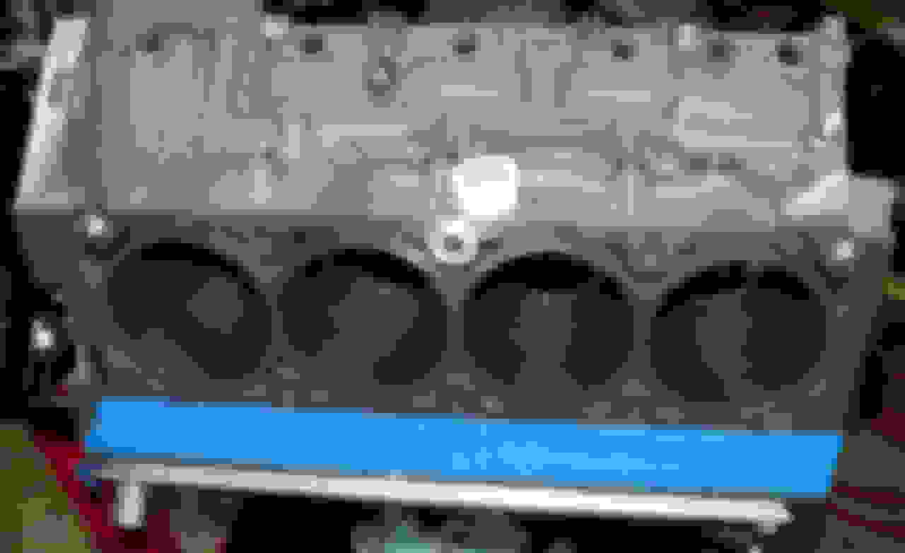
Bare Block. So at the time, early 2012, I was not aware of any machine shops in the Florida-to-Mississipi gulf coast panhandle area that had a LS-engine torque plate, required to correctly hone the cylinders in an LS block. Consequently, a fully machined LSA block, as shown in the GMPP catalogues, was purchased from Pace Performance for roughly $2k plus about $150 for shipping.
Block preparation was fairly minimal and really covers 3 topics:
1. Measurements
2. Deburring, stroker notching, oil passageway cleanup
3. Cleaning
4. Cam bearings
5. Oil squirters
Measurements: In order to determine everything is to spec, you will need some measurement tools beyond that of a simple caliper. The description of the process can be found in various books and online sources, so I won’t go into it here, but you can PM me with SPECIFIC questions. As an engineer, the company I work for does these type of measurements in a far more modern way, with some methods almost fully automatic. “Old school” for me works very well as this is almost a meditative after-normal-work-hours activity. I will throw a few pictures of my setup and a screen shot of the spreadsheet I use for calculating clearances. Again, if you have SPECIFIC questions, just PM me.
Deburring, stroker notching, oil passageway cleanup: While the Compstar rods appeared to have some clearance with the lower bore, I still notched the bores and used modeling clay to get a better estimate for actual clearance of the rod end as it swings near the bore. Notching was done carefully with a die grinder and head porting bit. LS1Tech and other sites have some information on notching. That said, given the Compstar rods with their clearance, all that needed to be clearance was the block casting in the oil squirter area. The cylinder sleeve itself was not in the way (at least 0.2 inches clearance with the Compstar rods).
That said, after notching the block, I had actually cut my knee of all things, by haphazardly sitting down on a nearby chair and ramming my knee into the side of the block (ouch!). It was kind of a freak accident as I usually wear one of two aprons I have when working on ‘delicate’ things such as motor internals, and it being Florida, shorts are generally the norm, so the exposed knee got a helluva surgical type slice. Consequently, I took to dulling all the hard external edges with several shapes of hand files as appropriate to the edge or location of the hard edges. Hard edged oil passage entrances and exits were also smoothed over with the die grinder.
Cleaning: Make sure to clean the block and all the oiling passages as many times as you feel comfortable with and then some. That said, I must have cleaned the block thoroughly with combinations of compressed air and soapy water baths about 4 times total over two weekends. I also used a shotgun cleaning rod and rags to make certain the 2 long and 1 short oil galley runs were thoroughly free of anything. The LS block is nice in that the main oil gallies are open ended at each end of the block so you can thoroughly run a rod and lint-free rag from one end to the other. The small oiling passages leading to each cam bearing and then main can be cleaned with a very small bottle brush. Flushing water thru the gallies and these small passages as well as those to the lifters, you should be able to see plainly and clearly. Now is the time you should run a thread cleaning tap with a little WD40 thru all the head bolt and main cap bolt holes. Make sure the holes are lubricated, but not dripping in oil. Anything dripping may actually drip onto something you don’t want it to later in the build as the motor is rotated on the stand.
Cam bearings: These are installed just like any other typical push-rod V-8 block. There’s plenty of information on how to install them. The Dura-bond performance bearings have that quality look to them like King Bearings do.
Oil squirters: OEM LSA oil squirters will not clear a 4.0 inch crank as the installed rods will not rotate pass them. The squirters use a common metric thread size M10x1.5, and I sourced a low profile socket head bolt M10x1.5x12mm from McMaster-Carr, using ARP PTFE thread sealant on the threads.
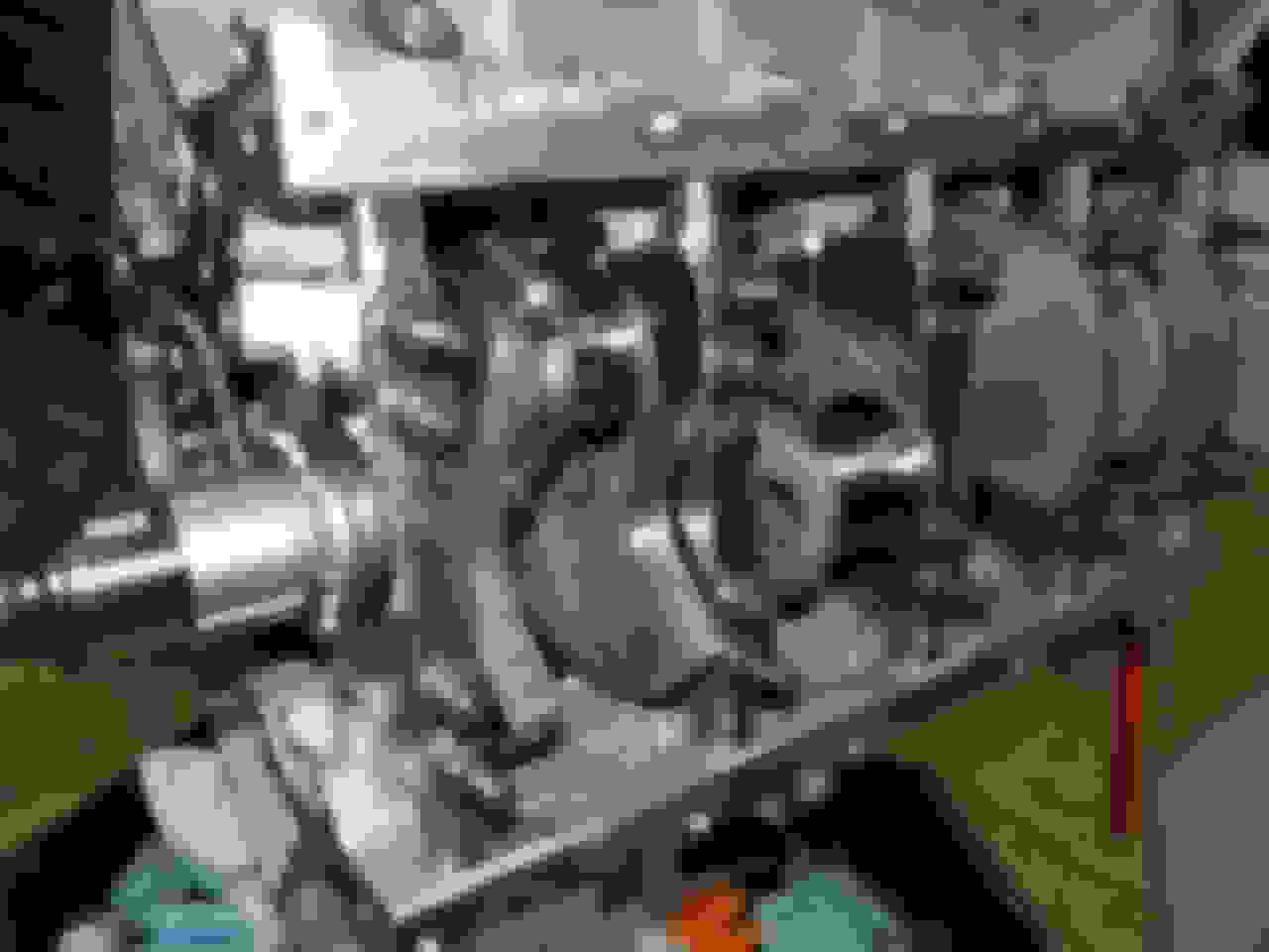
Cam Installation
In my opinion, a bare block is a great time to put a cam in. With the crank out you can see better where the cam is or is not going and help guide it along better thru the cam tunnel. I cover the lobes with blue painters tape, coat the journals with assembly grease, attach a typical install handle to the cam and install.
Once in, I pull the tape off the lobes, clean the lobe surfaces of any adhesive, and apply assembly grease to the lobes. Then install the front cam retainer plate, and then install a cam gear with a single hand tight bolt to keep the cam from accidentally moving off the cam bearings. Cam was spec’d by Martin Smallwood of Tick Performance after I thoroughly described what the motor was going to be and it’s installed application. Interestingly, while it sounds like a beast compared to say, my daily drivers, it really isn’t too loud “once” it’s warmed up. And I will say, with the plastic LS3 manifold, it was louder, but with the Holley Hi-ram (which is what it was spec’d to), it’s noticeably more quiet.
Last edited by ducatisl; 04-04-2020 at 06:28 AM.
Reason: Updated for most recent changes
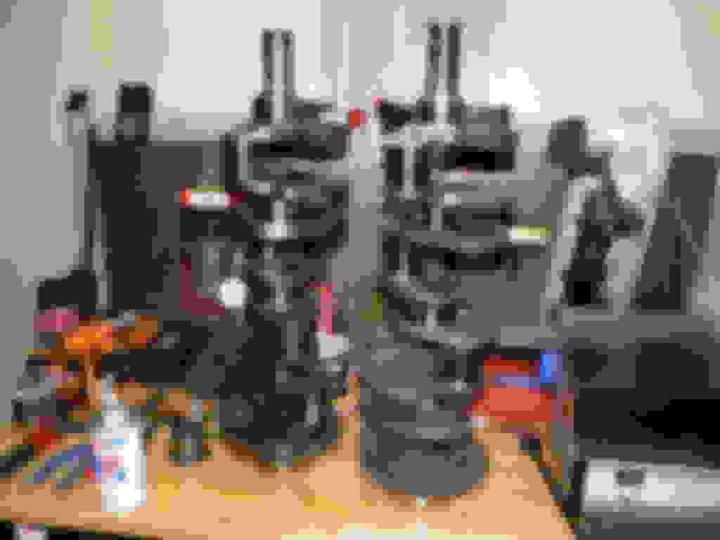
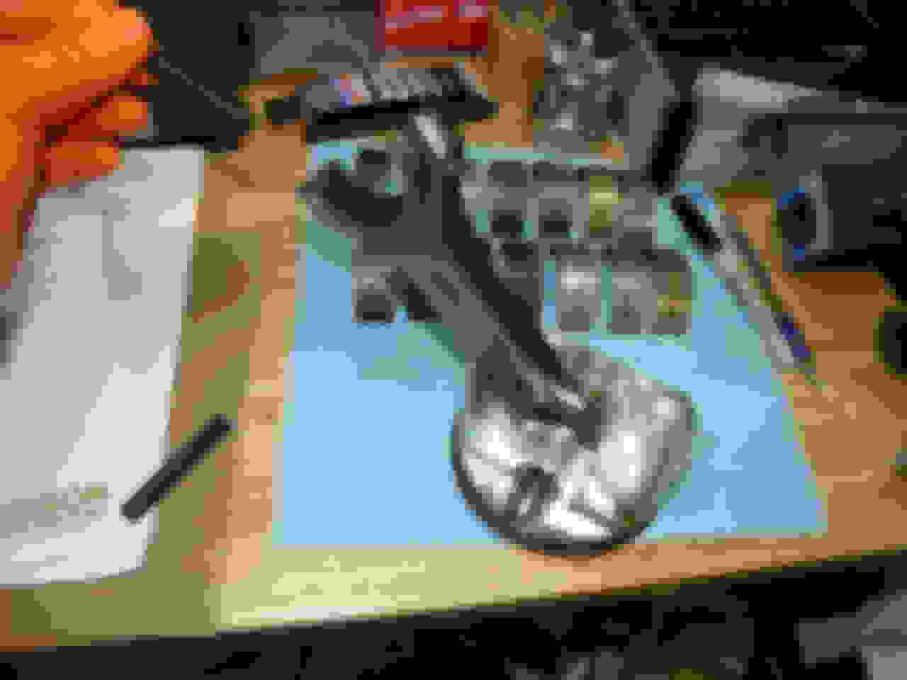
Rotating Assembly
Crankshaft. Rotating assembly was something that I really wanted to be a little different on. I�d like to think I�m not one that follows fads or hype and I know Scat has been around decades building cranks (Google Tom Lieb of Scat), so I went with a standard weight 4.0 inch stroke forged crank. Glad I did as the machinist who balanced it says he balances more Scat cranks than others and they�re very consistent.
Rods are Callies standard off-the-shelf Compstar LS rods, 6.125 center-to-center with standard size big end and the typical 0.927 small end for floating piston pins.
Pistons are Manley forged 2618 alloy that fit the 4.065 standard bore size, -18 cc dish, which combined with 66 cc chambers and the new Felpro Permatorque metal multilayer 0.042 head gaskets should net 10.1:1 compression. FWIW, unless it�s below about 50 degrees, I do not hear piston slap. When it�s so cold that I do, those are days I generally don�t want to be driving the beast anyways. I think the relative lack of piston slap speaks volumes for the Manley piston design, although, in all likelihood, they�re probably made by another company, regardless, I like the results.
Rings are the Total Seal steel ring option by Manley. I gapped them for a 300 shot of nitrous, so top ring 0.028, second ring at 0.030.
Bearings were King XRP�s, their coated race bearings. I�ve used Kings before and always liked their quality over Clevites actually.
After receiving all rotating assembly parts (Flantlander Racing, I�ve bought many engine parts from them in the past) and having the crankshaft balanced locally, I weighed everything to a tenth of a gram (fyi, a single sheet of 8.5x11 copy paper weighs about 4.5 grams), marked the parts, and logged this in a spreadsheet. Then I mix and matched connecting rods to rod bearings to get rod&bearing weights as equal to each other as possible.
Engine Assembly
Assembly is fairly straightforward, not rocket science, just need to pay attention to details and keep everything clean. For covering every little LS-related detail, I suggest getting one of the several books relating to LS engine rebuilding that are available. I used:
How to Build and Modify GM LS-Series Engines, Joseph Potak
How to Rebuild GM LS-Series Engines, Chris Werner
I want to say that Werner�s book was ever so slightly more useful.
Cylinder wall prep. I start with the application of Total Seal Ring�s Quickseat. On a clean cylinderwall, apply WD-40 uniformly to the surface and wipe off. Next apply the Total Seal product to the wall lightly. The wall, if clean to begin with, will turn green.
Crankshaft/mains installation. The obvious next step is to then rotate the engine on the stand till it is upside down, and install the upper main bearing halfs into the block. They and the main bearing saddles should be clean and dry. Next, apply a small amount of your favorite assembly lube (I used Joe Gibbs Engine Assembly Grease) onto that bearing half surface. The #3 bearing will require application to it�s vertical thrust surfaces. For pieces that are in contact but do not move, I do not apply lubrication of any type. That should be obvious I hope!
Next, carefully place the crankshaft into the engine, on those bearings you just lubricated. Then install the main studs, by hand, just finger tight. On a clean table, install the clean and dry lower bearing halfs on the main caps, then apply a small amount of assembly grease onto the bearing surfaces. Now carefully, paying attention to cap number and orientation, slide the cap over the main studs evenly and with a plastic mallet, gently tap evenly into place. Once all caps are on, apply a light, even amount of ARP lube on the stud threads, then place the ARP washers and nuts on the studs and evenly hand tighten. I�ll leave the rest of main cap assembly to ARP and LS specific books as it also involves thrust (#3) bearing alignment.
Piston rings/rods/installation. Rings were gapped 0.028/0.030 with an electric Proform ring gapping tool. Callies� quality was evident in their Compstar rods with each pin fitting perfectly. The Manley pistons had a great quality feel about them as well. They�re a forged side relief piston with the pin bore peeking thru the oil control ring groove, which requires a support ring to be put in the groove after the pin is installed. An adjustable aluminum ring compressor was used and with the GM bore chamfer, the piston/rod assembly went in like butter.
Windage Tray. This is also the point where you will want to put the windage tray on. The stock windage tray will interfere with the longer rod throws of a stroker crank, so you will need to put washers on the studs and possibly need to bang out a couple places on the tray where a rod bolt gets too close. I use a digital camera a lot since I really need to be wearing granny glasses for close up work. Plus it gives you peace of mind later in the night when self-doubt sets in!
Timing chain/gears. I find this a good point to install the timing chain, which given the multitude of choices out there, I went with a tried-and-true Cloyes billet gears (the one with 3 keyways, not 9), and their IWIS-built (C5R) Z-chain. I suggest getting an inexpensive damper install tool to help get the small cam gear on the crank as well as the oil pump drive gear later during the build. Make good use of any old pump gear not being used. They can be helpful in getting the gears on. That said, I highly suggest getting the Kent Moore Gen III 3 Crankshaft Sprocket Remover J-41558. You would not believe how much of a timesaver this tool is. I got mine used off Ebay for about $40 bucks. After installing the lower gear, the large cam gear will have to be installed along with chain, at the same time, with the timing marks aligned. Read the Cloyes instructions that came with the chain as not all timing marks are as they seem. Cloyes also say they hand pick the individual components and it shows: chain had far less slack than the original LS3 chain.
Timing chain tensioner. Speaking of LS3, I yanked the notoriously problematic LS3 tensioner out and installed the reliable LS2 tensioner. Fyi, a majority of my new OEM parts I bought thru GMPartsDirect. Keep in mind, while they have nice prices, their shipping prices are generally high. No such thing as a free lunch. Another source for GM parts I used was Nalley GMC. They have a nice online system with parts drawings. The bane of Nalley is it takes well over a week to get any part from them. Now that the timing chain is on, it�s a good time to degree the cam. Again, it�s not rocket science, and the procedure is the same as for any other pushrod V-8, and is well documented in both print and online media. Having that Kent Moore tool will help immensely if you need to reposition the lower cam gear.
Piston ring filing, ring installation, and piston-rod assembly is another topic that is generic and can be sourced elsewhere. What I�ll add is that:
1. A useful rod installation tool is worth A LOT more than the $25 bucks or so that Proform and others charge. Using one will allow for nick-free and thus stress-free installation of the rods onto the rod journals.
2. Use an actual ring gapping tool.
3. Good rods and cranks will have very consistent measurements. Coated bearings�not so much.
4. Total Seal Rings makes a ring assembly lubricant specifically made for ring installation and I use this in the ring grooves upon ring assembly, as well as on the piston skirt coating.
5. Keep several new Sharpies around. No one ever killed a part by writing on it too much.
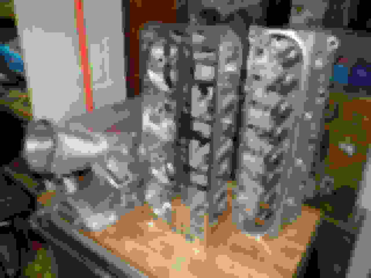
Cylinder heads I knew were going to be LS3-type, but considering I wanted to eventually boost the motor, I settled on the stronger LSA castings. Since I still had some friends and professional reasons to frequent Indianapolis, I ended up going with ex-Katech porter Brett Land who had moved from Detroit to Indy. While in retrospect, I probably spent a little too much on the heads, I did get top quality parts (Ferrea hollow 2.165 intakes valves and 1.60 Super Alloy high temperature exhaust valves (apparently better than Inconel), BTR springs) and some head porter and valve job trickery unique to someone with Brett�s background working with actual GM engineers on rectangular port head development.
That said, Brett kept most of the LSA swirl inducing wing in the intake, those ports still flowed 345 CFM. Before anyone starts criticizing flow numbers, keep in mind that you really aren�t supposed to buy an already assembled head and assume it�s just a bolt-on. Springs need to be set up for the amount of lift of the cam, so the whole process of measuring installed height, coil bind, and shimming, all work together so you know your valve springs are not only NOT binding, but you know precisely how much spring pressure you�re applying when the valve is both open and closed. This said, having someone like Brett take your cam card and rocker information and correctly set up the valves is definitely a value-added service that will save you time and give you peace of mind. That said, I would still check rocker swipe pattern on the valve tips as a double check.
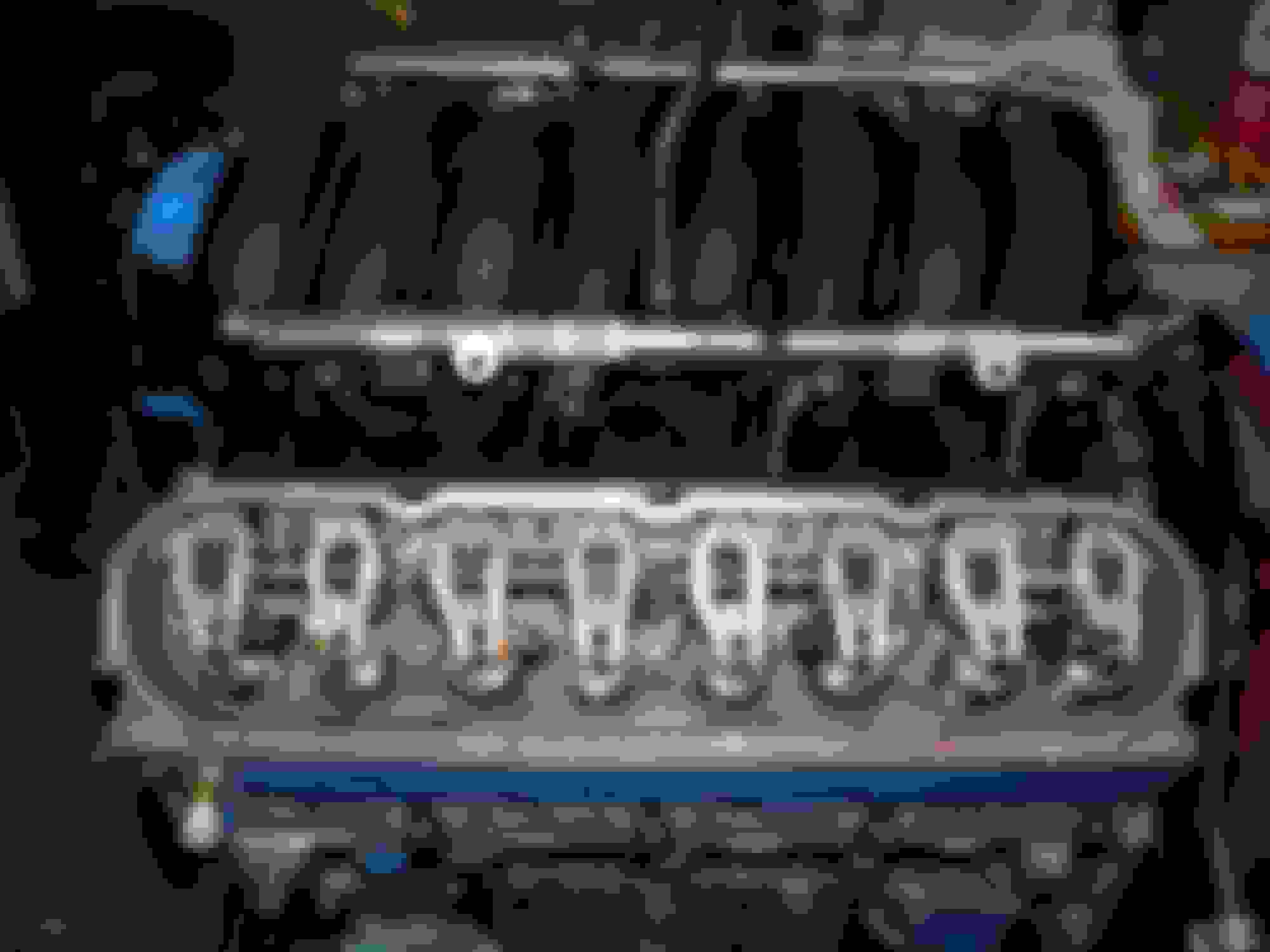
Lifters. So once the short block was assembled, it was time to install the heads. But before that can be done, the lifters need to be installed since there is no convenient side valley window like what�s on a LSX block. At one point I felt like going with a link-bar lifter like a Morel, but in the end felt the 7300 rpm limit I was shooting for would be adequate for a stock type lifter and went with Brian Tooley�s Slow Leakdown Rate (SLR) lifters. These are installed in the plastic OEM lifter buckets just like the stockers. Again, I used Joe Gibbs Engine Assembly Grease, but fairly liberally in this case, coating the sides of the lifters, the roller, and the pushrod bucket thoroughly.
[IMG/]http://imageshack.com/a/img902/901/tDb8xI.jpg[/IMG]
Head gaskets. For head installation, you will have already weeks/months ago already figured out which head gasket to use as any compression ratio calculation requires one to know their head gasket thickness. Felpro�s Perma Torque MLS head gaskets would give a decent range of compression ratios to work with for a normally aspirated/centrifugal setup given my piston dish volume (-18cc) and combustion chamber volume (67cc) of between 9.8 and 10.1 depending on whether using their 0.041 or 0.053 gaskets. ARP head studs were first installed, hand tight. Then the head gaskets received a light coating of copper spray, and then gently installed thru the studs. Heads were then gently installed and then the ARP washers and nuts installed with ARP lube. ARP provides thorough directions with their head stud kit.
Rockers/pushrods. Once completed, the pushrods and rocker arms can be installed. For a detailed set of instructions, I suggest, again, looking towards the LS books or online resources. This is the subject of both rocker setup and pushrod length checking. Given that pushrods are generally available in 0.025 inch length increments, well�it�s a long subject, so I suggest further reading to do this. For the record, I use BTR�s 5/16 pushrods (didn�t want to chance 3/8 not working), and Yella Terra non-adjustable roller rockers. Rockers got 45000 miles on them at this point since they were installed early on in the stock LS3 motor. In standard small block procedure, very lightweight checking springs are used to determine piston-to-valve clearance, which on this 10:1 compression motor was very large (>0.150 inches both valves).
Oil pump. At this point, I install the oil pump and I highly suggest researching LS oil pump installation. I used the feeler gauge package available thru Schumanns, who by the way, make some really nice oil pumps. Once accurately centered and torqued down, I remove the front cover of the oil pump and pack it with, yes, again, Joe Gibbs Assembly Grease. (Gotta say, I love JG�s Assembly Grease, but prefer Amsoil�s engine oils. ) The next step should be obvious: install the oil pump pick up tube. Use the correct o-ring, and if you spaced out the windage tray, you may need to space out the pick up tube stud mount as well. For whatever reason I can�t remember, I ended up installing a Melling 10296 and left the high pressure spring in. Combined with the little detail work I did on the oil passages, I have roughly 65 psi cold, and 45 psi hot.
Main seals/covers. All that�s left hardcore-wise are the front and rear main seal covers and oil pan. A couple really sweet tools that can help you here are Saccity Corvette�s seal alignment tools specific to the LS engine covers. They also have some very helpful Youtube videos on the use, and thus LS seal installation, of their tools, and obviously cover the importance of cover alignment as these two covers are what the front and rear of the oil pan bolts to.
Oil Pan/Trapdoor Baffle/Dipstick tube. Improved Racing�s trapdoor oil pan baffle was installed. It�s definitely a nice piece and easily installed if the pan is out. A new dipstick tube was installed since I really bent the cr*p out of mine, and they�re very inexpensive as I recall.
Intake Manifold. Intake manifold is a Holley Hi Ram with the 102mm lid. Brett ported the lid transition area and then the base where he port matched the runners to the intake ports. The beauty of his CNC mastery is not only nice flowing intake ports, but perfectly matched runners leading into the ports. I waited 4 months, but the end result was well worth it in my opinion. Fwiw, after doing my Holley, Brett said he�d never do another one again LOL. So if you ask him, be prepared to bribe him heavily if you want it done. Now at the time of the engine install I did not have a COPO-type of cowl hood that would clear the Holley, so run-in and break-in were done with the plastic LS3 intake manifold.
Engine Install
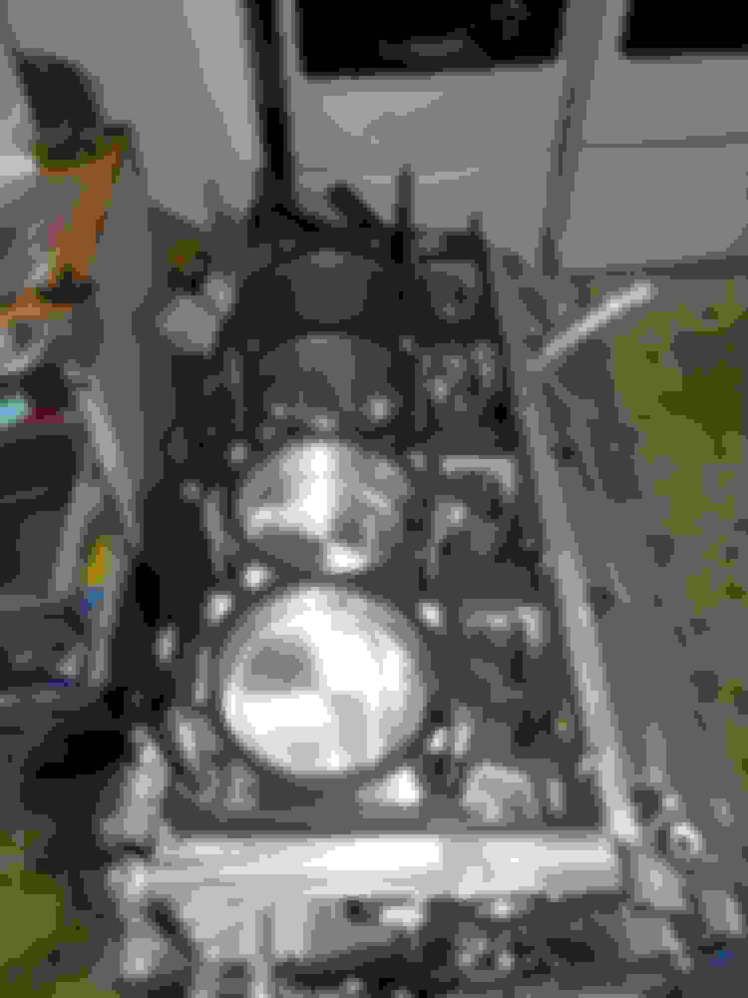
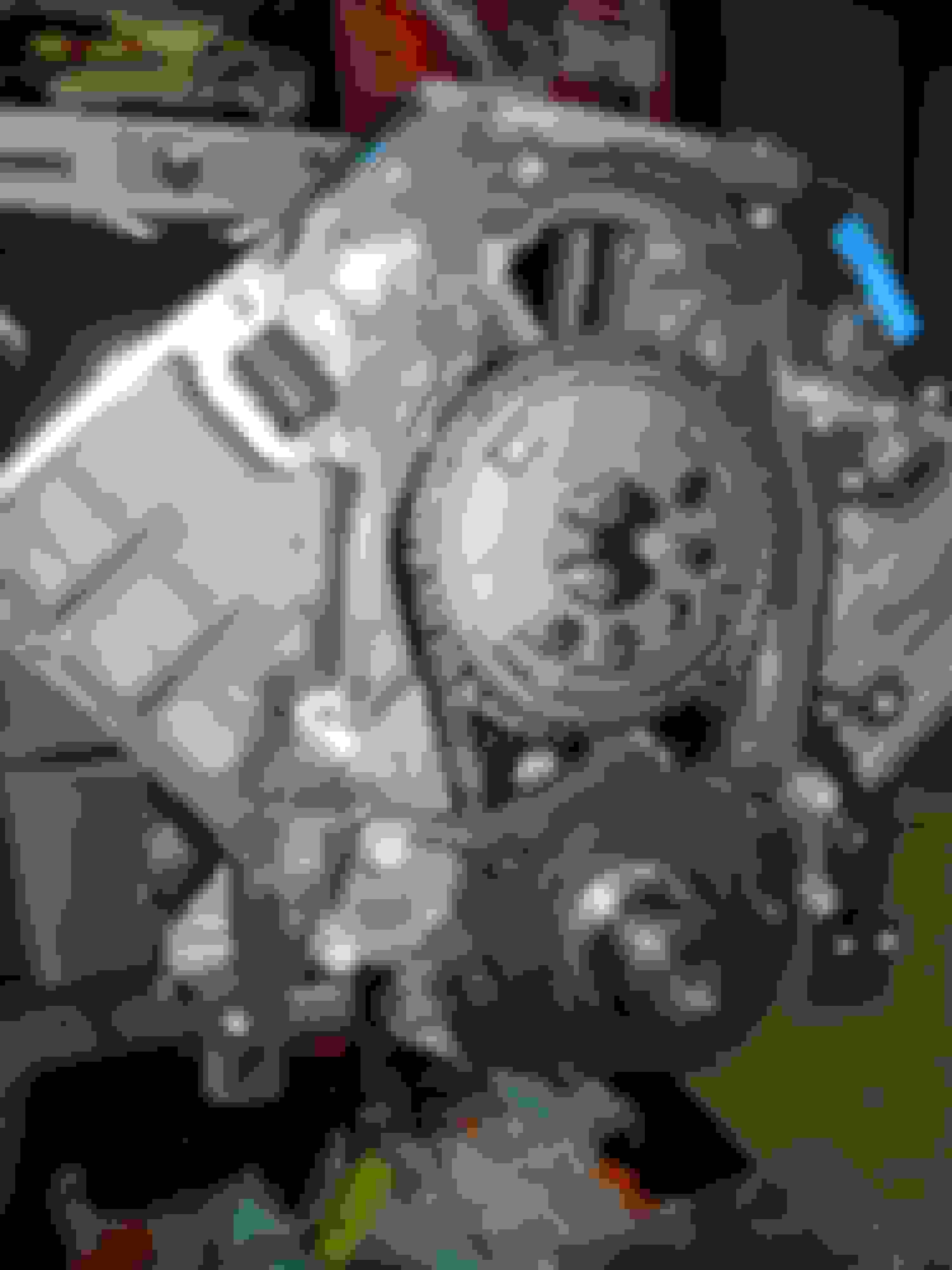
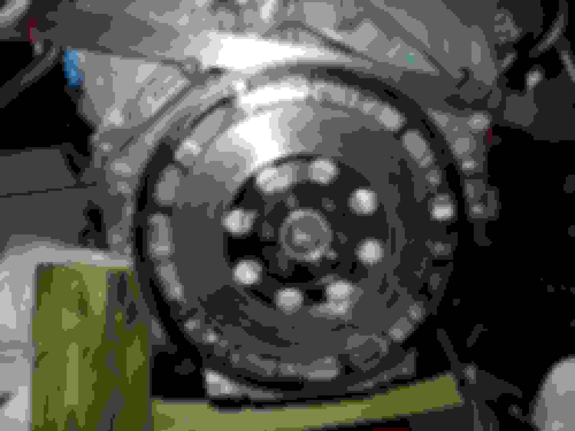
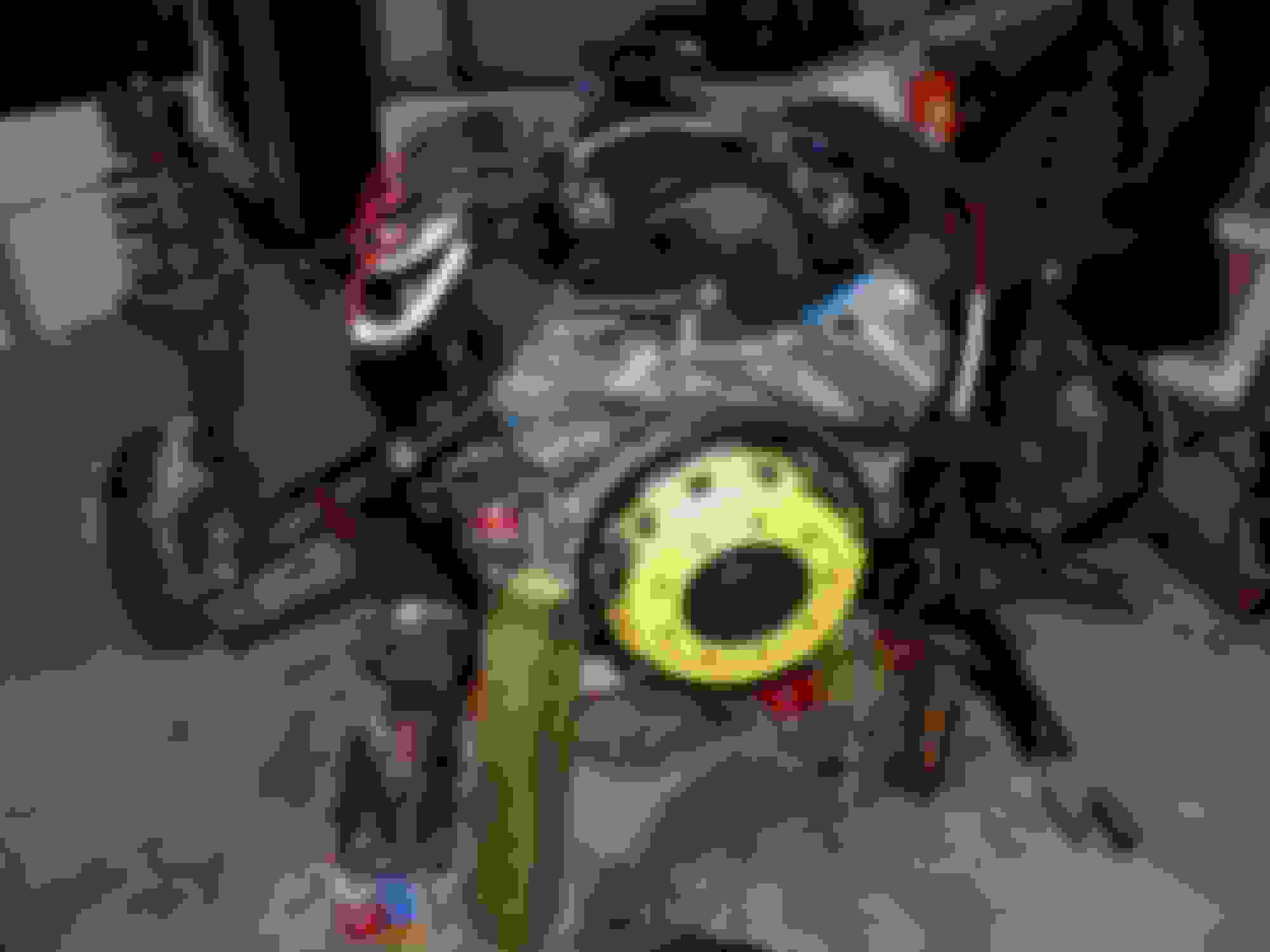
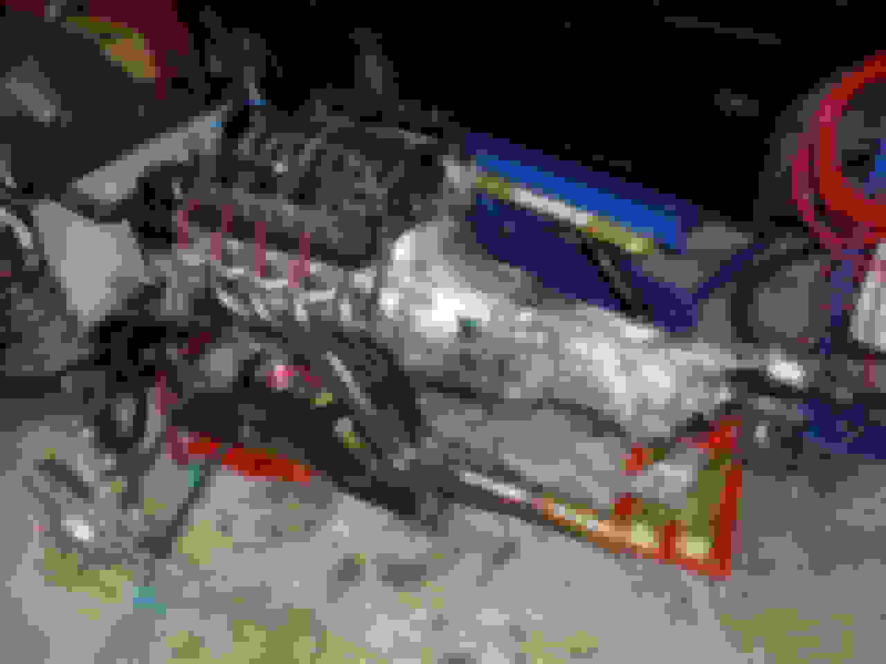
Install from below. Motor was installed onto the K-member on the garage floor with the new Prothane motor mounts, my poor abused 3 year old ACT twin disk clutch was bolted back on with new ARP flywheel bolts and generic chromoly nuts for the pressure plate, and the tranny bolted on, all on the K-member, resting on 4x4�s on wheel dollies. I bolted on as much as I could while everything was out in the open: electric water pump, alternator, headers, spark plugs, intake, fuel injectors and rails, throttle body, etc. To try something a little new, for exhaust gaskets I installed the soft metallic _______________, and of course, the Stage 8 locking header bolts. FWIW, the clutch, an early ACT twin, was reinstalled, and it works, although it�s seen way better days:
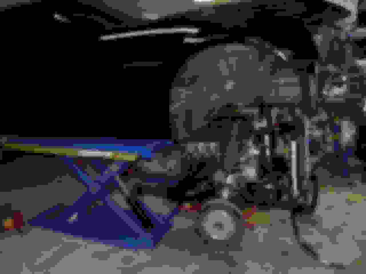
With the clutch and transmission back on the engine, the whole assembly is rolled underneath the car and the car is slowly lowered over the engine/tranny. There will likely have to be some slight side-to-side shifting while the driverside header is making its way around the steering shaft, but other than that, it�s SO MUCH EASIER installing the engine from the bottom than the traditional cherry picker lowering the engine from above.
Coil Relocation. Proform�s black crinkle finish Chevrolet valve covers were used, and while I originally used Proform�s coil brackets, I ended up creating simple relocation brackets with simple aluminum spacers and L-brackets. Ignition wires were Taylor Thundervolt 8.2�s that I cut to length individually and crimped the LT1 straight coil sides on.
At this point, I�m not even going to gloss over the rest of the remaining tasks from a typical engine install: a/c compressor, heater lines, radiator, power steering, engine power/grounds and wiring harness, shifter, transmission crossmember, driveshaft, and exhaust.
Engine Break-In. Prior to engine run-in, an actually just before the engine was lifted up into the car, the oil galley plug near the alternator was removed and a Earl�s metric-to-6AN fitting was installed and then a 6AN-to-3/8 hose barb so that the oil galleys could be primed. With the valve covers off, the engine was primed until oil could be seen leaking out of each rocker. Priming was done with a Brakemotive pressure bleeder feeding Joe Gibbs BR30 at about 25psi.
Engine run-in was performed for about 15 minutes probably while checking for leaks, etc, and then that oil dumped. Break-in was performed in increasing part throttle stages, 3 sets, with logging for a pseudo oil-life-monitor calculation, with oil changed about 3 times then as well. The final break-in oil change was left in while the car was driven normally for about 2500 miles. Run-in oil was Joe Gibbs BR30, and break-in was Amsoil Break-In 30wt. Both of these oils have nice ZDDP levels with minimal or zero detergent that could get in the way of surfaces that could use ZDDP (which is probably none for a roller cam motor, but never hurts to be on the safe side).
Filters used since were either Wix, K&N (2 types), Amsoil, or Afe. Every used oil filter has been cut open and the pleats removed and inspected. Filters used after break-in have been Wix, K&N (gold), and Afe. FWIW, the Afe filters are internally identical to the Amsoil, the difference being the much thicker case and a 3/8 inch square female lug at the end to facilitate removal. I continue to use Afe/Amsoil filters. Valvoline VR1 10w30 conventional oil was used for 2 oil changes after break-in, and Amsoil Z-Rod 10w30 since then.
Catch Can. A Mighty-Mouse catch can (the one with the PCV valve) was used which finally solved most intake oil ingestion. I had a Norris and RXT catch can in series that struggled to keep up.
PHASE 2
Hood. From break-in (August 2013) onward for the first 5200 miles, the engine was run with the plastic LS3 intake. Around March 2014, I decided to do the rear end swap and fuel system upgrade. This was precipitated by finding a Harwood cowl induction hood on Ebay, and it turned out to be a local seller I had bumped into at one of our Emerald Coast Camaro club cruises. The Harwood hood is a bit extreme, I must admit, but it definitely has helped in setting the bar on the other extreme: no underhood structure, plenty of clearance for the Holley. The hood I could really use is the MPD Copo hood, but given how I don�t daily drive the car, maybe the Harwood is perfect. It �is� as light as possible for a Camaro hood. 8.5 lbs as I recall, plus the OEM hinges can be removed shedding some more weight. If you go this route, don�t forget to attach a hood liner of some sort. I got the Dynamat thick version which was only about $50 bucks at Summit.
Holley Hi-Ram. Besides vertical clearance at the hood, the Hi-Ram needs horizontal clearance at the cowl. Thinking ahead, before I dropped the original motor, I placed the Hi-Ram on the heads and moved it as far back as possible, but still it was about a intake port�s width too far forward still. So, I marked on the on the cowl where to cut and in about 10 minutes had cut the necessary sheetmetal out so the Hi-Ram could fit�short of the windshield wiper rod going to the passenger wiper. That can be easily popped off the linkage allowing the Hi-Ram to fit while still allowing for driver�s side wiper operation. FWIW, I had replaced the OEM engine mounts with the Prothane units which looked to be about a ��inch shorter. Cowl still
needed to be cut.
Fuel System
Fuel pumps and injectors. Considering the goal of 800-900 rwhp, I knew from the start that a new fuel sytem was in order. I figured a dual Walbro 267 pump setup would be perfect with -8AN Teflon feed line and the stock 3/8 feed as a return. The hat was a Fore Innovations CNC hat, and I also bought their inline fuel filter with the 1/8 inch NPT pressure port. Injectors would be of the 1000cc variety and I settled upon FIC 95 lb/hr after talking directly with John the owner. FIC provides the needed data in the correct HPTuner format, and it works well. Stubbornly, the only injector issue was that the Holley manifold is drilled for fitting the rails with the longer 65mm LS1-type injectors. I ended up using FAST lower injector spacers on the LS2-length (48mm) injectors. Is it ideal? Probably not, but it works.
Hose and hose end fittings, etc. This brings the journal to the point of laying all the hose, measuring, drilling, cutting, attaching fittings, testing fittings, and so forth. Since the rear subframe was dropped for installation of the Strange, not really necessary, but considering the exhaust and driveshaft were out anyway, it�s quite literally only 4 large, easy to get to bolts, I decided to remove the fuel tank to install the hat. Additonally, I took the reciprocating saw to the floorpan just above the fuel hat location. I never trust AN hose fittings till they�re both tested and shown to not leak while under operation. Having a cutout I can remove is an easy way to check the fuel fittings at the top of the hat. After counting all the fittings I would need, it turned out there would be 16 new AN fittings, and after looking at alternate places for Teflon fuel hose, I came across a really nice coated stainless steel Teflon hose from ANFittingsDirect and they also had decent pricing on Teflon hose ends too.
Hose routing. So from the pump, the line goes over the right side of the tank, and then snakes around into that raised hollow floorpan area that exists lengthwise on both the left and right sides of the car. I saw a vendor post some pictures of running his fuel lines in this area and thought it was a great place for routing, and this is where I placed the external fuel filter. Be careful, the floorpan in this area is paper thin and will hold almost nothing. I used a couple sheet metal screws and JB Weld to secure the filter bracket. Additionally, I found the appropriate metric-to-NPT fittings to adapt the OEM fuel pressure sensor to the filter outlet, and of course, this necessitated extending the wiring harness for this this sensor. The Teflon hose then continues from this filter and into the floorpan bulkhead at the below the passenger door hinge area. A step drill works great to enlarge or create holes in sheet metal. Exiting the bulkhead the hose will need to be snaked along the lower edge of the chassis rail above the k-member, and then out the access hole inboard of the front right strut. Quality self-tapping screws from McMaster-Carr were used along with insulated loop clamps. Once into the engine bay, the -8 hose runs to a Magnaflow distribution block with 4 outlets, 2 go to the fuel rails, the remaining 2 are plugged but could be used in the future for a wet nitrous system. From the rails, fuel exits to a manifold referenced regulator, which for convenience is mounted directly to the passenger side rail. The return exits the bottom of the FPR and goes to the old OEM fuel line. That OEM fuel line utilizes those nice Russell hardline to AN adapters. One at for the FPR return hose, and the other end for another hose going back to the fuel hat return.
Fuel Electrics.
This is kinda an easy part. First, toss that FPSCM module out of the car. The Fore fuel controller is just a glorified relay system, but a very well built one at that. Wire it like you would a high end car audio amplifier and with a few changes in HPTuners to ignore the lack of a FPSCM, you�ll be good to go. I already had an ignition switched +12V source in the console, so I pigtail off of that to turn on the first fuel pump. I will say, do NOT underestimate how much a fuel system can cost. Sure, you could run the stock line and do a OEM-like non-return system for a lot less, but as soon as you cross that line over to a return system, all those fittings and feet of fuel line will start to add up fast and you�ll find yourself just north of $2k just in parts.
Nitrous control. I use a simple NOS 2 stage window switch. Simple. Reliable. 2-stages of output wires, with power/ground inputs, TPS input, RPM input, and shift light output. I say this because I use the shift light output to turn the 2nd fuel pump on at the Fore fuel controller. Quite handy, and a clean, simple, reliable setup. That said, I use an Autometer 9177 tach signal box and wire it per the video on their site. I believe this to be the most reliable way to get a strong, clean, RPM signal.
Remote Fire Suppression System
Having described the new fuel supply system and all it�s possible sources of leaks, and having had a car burn to the ground before, I decided to install a remote fire extinguisher system. Using -4AN hardlines and braided lines, one circuit terminates above the fuel hat area, and the second circuit feeds nozzles on each side of the engine. The setup is a Firecharger aqueous system that essentially uses water and soap mixed under pressure from a CO2 cartridge. In addition to ensuring water was getting in the right places with no leaks, I did actually test with the full water AND soap (it has a sexier name than �soap�, but essentially it�s an animal fat derived product which is�soap) accidentally, and let me tell you, it foams up like you wouldn�t believe and I have no doubt that it would put out a fire very easily. I sourced my system from Nick at Augusta Motorsports. He�s definitely a small mom&pop business, so contact him if you�re looking for something like this. Note the placement of the fire suppression lines in the front right wheel well above. Note that in the front, I run a 20x10.5 -35 offset wheel with 275/40 tire, and there is ZERO rubbing of that tire/wheel on anything.
ECU relocation. In order to install the vacuum pump, the ECU must be relocated away from it�s location on the side of the fuse box. Since I had already cleaned up a lot of the wiring harness around the injectors and coils, it was a simple matter to move the ECU to the fender side of the fuse box.
Vacuum pump. GZ Motorsports VP102 vacuum pump then solved all the prior catch can inadequacies, although the Mighty-Mouse can does VERY well. So liking that can so much, I decided to simply use it as a vented catch can by plugging the PCV end and removing the rubber �safety valve� disc at the base of the filter. Mighty-Mouse, like the Norris can, use standard thread sizes that can take �AN fittings and plugs, so reconfiguring is always easy and professional looking.
Katech�s serpentine manual adjuster bracket was used with the GZ Motorsports LS idler pulley and a 46 tooth pump sprocket. Fresh air enters a small K&N filter on top of the higher flowing VCR102 adjustable vacuum relief valve mounted on the driver�s side valve cover, with dirty air exiting the passenger valve cover thru a standard Moroso billet valve cover breather (p/n 68788), which, like the Mighty Mouse can, contains a big wad of metal mesh to help separate out oil.
This is the big issue that led me to the decision to redoing the fuel system. I realize one can remove the diff and driveshaft without removing the fuel tank, but given how easy it is to drop the rear subframe, I figured I�d kill 2 birds with one stone.
Strange rear end: The big Dana-style rear gear setup is the strongest setup shy of a Ford 9 inch, but only because the Ford�s pinion is supported on both ends, not cantilevered like all the other designs including the Dana. However, the Dana�s pinion gear position is in a more efficient location than the Ford�s. The Strange gen5 housing is an awesome piece and weighs about 20 lbs more than stock. Everything about it screams quality, starting with the CNC aluminum axle stub seal housings.
Removal/installation: this is very straightforward. Simply remove the axles or better yet, unbolt them from the axle stub at the differential. Beware now if you have aftermarket axles and a lowered car. The new stronger outboard CV joint is not real keen on lowered cars or being bent at odd angles during installation/removal. I now just disconnect all the linkages at the knuckle, then slide the knuckle off the axle, moreover, I usually remove the six bolts at the inner stub, as I�ve never been real consistent with getting the stub out or into the diff easily. Without all the attached weight, an axle stub will easily pop into or out of the diff.
Coilovers. The other major rear end item I wanted to accomplish was getting coilovers in. That said, BMR has a very nice setup for the rear consisting of chromoly control arms and Strange double adjustable coilovers, which considering if you got QA1 front double adjustables, you�d be looking at about $2k, which is really quite good if one considers that BMR has a matching Wilwood brake setup for this that will allow 15 inch drag radials to be run. Now in addition to this, I figured it was high time I ditched the street oriented Eibach rear swaybar and got the drag-oriented swaybar.
Control arms, trailing arms, bushings, alignment. Everything is so much easier working on the assembly out on the open. That said, I really wish I spent some quality time making extra, EXTRA sure all the bushings in the subframe assembly were good. Some loose trailing arm bushings really had me chasing my tail on changing toe alignment issues. Using the incorrect grease in the trailing arm bushings was the root cause and while the outer bushing is listed in the BMR website, you will have to contact BMR directly for bushings specific to their parts. I will have to say that I would urge people to deal with and order from BMR directly (Keith�s personal 5th gen is a BMR test vehicle so he knows the 5th gen well) as they have a record of all the parts you�ve ordered from them, which will definitely insure you get the correct parts for any upgrades or maintenance jobs. Some historical background: Eibach springs and swaybars had been mounted back in the 2010/2011 timeframe along with those beefy BMR trailing arms and toe rods. I kept the trailing arms, but the tubular lower control arms really pushed the toe more to the positive side than the aftermarket SPC adjusters could handle, and I ended up buying BMR�s adjustable toe rods.
Driveshaft. I took the path most traveled in the past, but least traveled today, and went with the single piece 3.5 inch steel driveshaft. I realize it�s heavier compared to a carbon fiber or aluminum driveshaft, however it is, in fact, similar to stock in weight, and hopefully more reliable. The extra width of the 3.5 inch driveshaft and the bigger proportions of the Strange rear end will force you to spend some quality time with the exhaust.
Exhaust. Back in 2010/2011, I installed Stainless Works long tube headers (2inch primaries, 3 inch collectors) and a Magnaflow 3 inch competition exhaust. The switch to a Strange rear end required the under-axle pipes had to be disconnected from each other (remove that lone 14mm head bolt/nut) and spread apart.
Shifter. Also during this time, I replaced the trusty LSR Tri-Ax shifter with a MGW. I knew the MGW was nice, but honestly, I didn�t realize just how nice it really is.
Issues after assembly. After getting everything back together, there were a couple issues that popped up: failing to tighten the transmission crossmember-to-transmission bolts (2), trailing arm bushings needed to be replaced (incorrect grease used), and fuel fillups take longer (replaced the 20 lb charcoal evap system with 3/8 hose and a rollover valve). Maybe it was intuition, but during this phase, I had decided to invest in some wheel alignment tools in the form of camber/toe measurement system from Quicktrick and some extra toe plates from Longacre. It took a few months, one �baseline� alignment from a local tire shop, and a trip to north Georgia to make a pathetic but scary �-mile run to figure out that a relatively new trailing arm bushing was shot.
Nitrous. The final engine mod, completed but still not tuned or tested as this is written, was to change the nitrous wet single-stage system over into a dry 2-stage setup. This was made possible by the tremendous fueling capability from the new E85-capable Walbro 267 fuel pumps used in the Fore fuel hat and the FIC 95 lb/hr injectors (103 lb/hr at 58 psi) fed by the large 5/8 inch bore Holley fuel rails. One 267 pump can deliver 380 lph of fuel, so to be on the safe side, 700 rwhp should be feasible.
The prior 92mm single stage Nitrous Outlet plate was replaced with their 102mm two stage version. I bought a couple of the smaller 200 rwhp capable nitrous solenoids and used the prior larger nitrous solenoid as a safety cutoff. Hardlines were bent from each noid to the plate.
Timing and fuel control are all done in the tune. Just haven�t had time to test it out as my favorite tuner, Ryan, left SS Performance. The next race isn�t until end of January, so I�ve got time to get this sorted out.
Throttle body. Since I�m using the 102 mm Holley Hi-Ram, I decided to ditch the VMax ported 92 and try the long awaited BBK 102mm throttle body. At first, there was difficulty getting the engine to idle using �what everyone else uses� for 102mm throttle body settings. I finally just put in numbers for actual throttle bore area and not the usual numbers. Poof! The BBK started working.
Gauges. Initially an Innovate Motorsports MTX-L wideband was used, since 2010. The 2014 install of a vacuum pump got me interested in measuring crankcase vacuum so that the vacuum regulator could be correctly set. Noting that the AEM AFR failsafe gauge also contains a MAP sensor, I decided to use that. This gauge does away with free air calibration of the Bosch wideband O2 sensor, as well as providing a ground signal above a specified AFR setting across the map range. I used this ground signal to shut off the main nitrous solenoid. The other gauge installed is a Aeroforce CAN-bus gauge. It�s pretty useful when not datalogging with a laptop. In fact, it doesn�t like it when the HPTuners dongle is installed at the same time, so using a OBD2 y-cable with the dongle and the gauge attached at the same time will not work. The Interceptor is very nice in that it can read codes and reset them, on the fly.
The only other gauge is a Autometer LED shift light. It�s the one that can count shifts and change shift light settings appropriately, but honestly, that�s a bit much to keep track of and I just use it with one shift light setting.
I mount everything together in a truck-style two gauge pod. Can�t remember the brand/model, but I wanted the gauges where I could easily see them, not on the pillar, but above as close to the speedo/tach as possible.
Seats/Harness. I realize there�s a whole mess of issues with lightweight seats and harnesses, but without getting into them, I�ll just say what I did: removed drivers seat (58 lbs with bracket/slider) and replaced with Sparco Evo2 US (25 lbs with fixed seat bracket from Wedge). Obviously removing the passenger seat is worth another 58 lbs. I�ve got both a 6 pt Sabelt and a Schroth 4 pt, but I generally use the Schroth since it has the DOT-legal latch/buckle. That said, the Schroth shoulder harness belts are mounted to
the rear seat�s left side belt mounts (right belt thru the seat, left belt between the seat and plastic trim), which makes it a tad difficult to remove the rear seat bench. That bench can�t weigh more than 5 lbs I�d guess. The seat back, however, weighs a bit more. That said, the rear seat is very effective in quieting down the car, and that�s after I placed some lightweight noise/vibration material on the floorpan under the rear seat as well as in the battery compartment. As far as the Sparco is concerned, it�s very comfortable when setup right and I�ve driven the car 6 hours in one sitting without complaint. What is worth complaining about is the squeaking from the seat! I�m still working on getting rid of it, but for now, it�s very irritating.
Minimal External Mods
Body. ACS (Advanced Composite Systems) front splitter with undertray, along with sideskirts were installed in just a couple mornings. Seeing as how black is the most common 5th gen color, I really wanted to stress �outwardly� that my 5th gen�s beauty is deep inside, not on the outside, hence the stickers along the side skirts of �functional� companies whose product(s) are contained within my car. No AAC or Oracle products here!
Wheels were added at the same time, and while I already had some Forgestar F14 18x10 rims for drag racing, I really liked the Niche split 5 spoke Targas, and unfortunately, they didn�t have the size I wanted in 19�s, hence the 20x10.5�s.
Miscellaneous
Radar Detector. Escort 9500ix. Bought a new 8500 x50 for a new Impala we got, and I have to say, for this little beach town I live in, the 8500 has everything that�s needed, might actually be more sensitive, and costs $150 less.
Laser Jammers. Laser Interceptor Quad. Definite must buy. Saved me a dozen times so far I�d say. They�ve paid for themselves already.
Battery. Deka EXT30L. 23 lbs, saves 24 lbs. It works, but if the staging lanes are long, you might consider just keeping the stock battery. Shoria LiPo batteries, specifically APP36L3-BS12, are currently the rage now, and only weigh about 5 lbs.
Thanks man. I figure with the car spending nearly two years in the air of four that I've owned it, I should spend a little time documenting what I've been going thru, especially before I start building another motor for it (I'm thinking 12:1 full-on nitrous motor). The only one I have to blame is myself since I do nearly all my own work. That said, I'm really liking how it's all turning out.
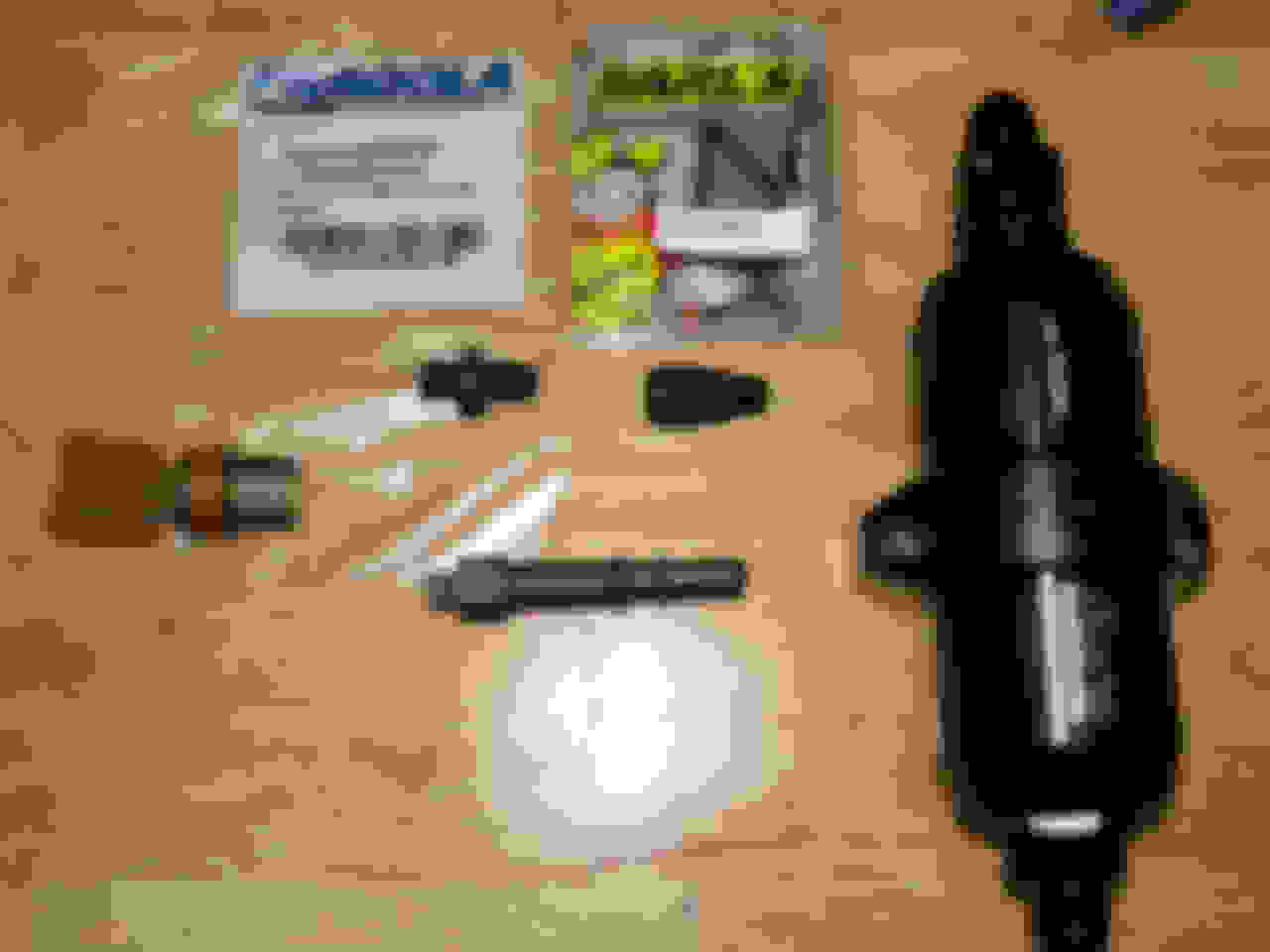
So got some extra pics to clarify the OEM fuel pressure sensor install on a the Fore return fuel system, first parts needed, then location to put the large fuel filter and sensor:
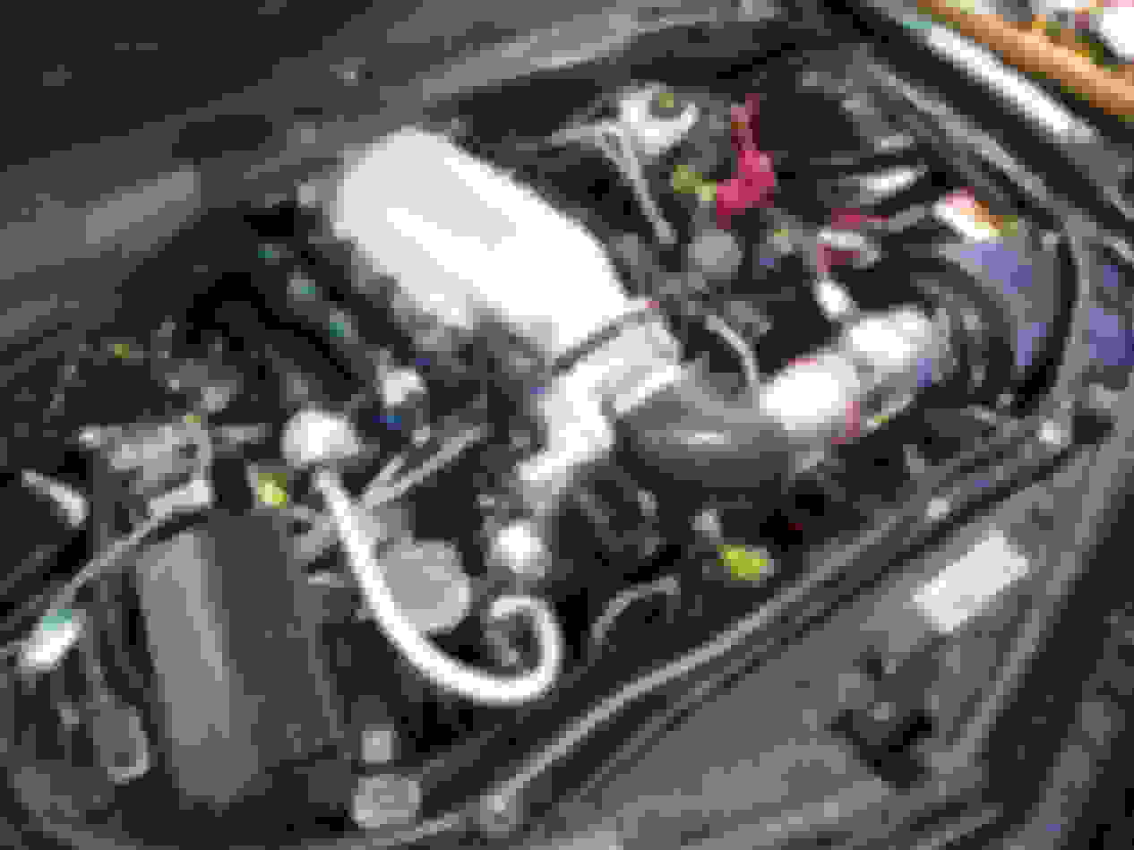
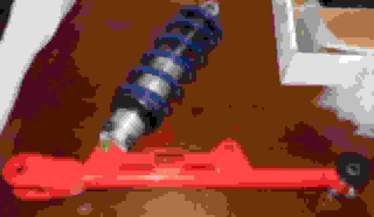
And finally, a better pic of what's underneath and all that is BMR and Strange Engineering and Driveshaft Shop goodness:
Thanks Martin. Love this cam you've spec'd for it. Been trying to drive the car a few days a week, even in base rush hour traffic. It's not too bad on the commute for what it is. Mainly working on transients in the tune when I can, but it's pretty close already.
Will get with you in a few months on the next cam for a build I'm starting this upcoming winter. Basically the same but high compression (12:1), small nitrous (<200 shot).
[QUOTE=
Vacuum pump. GZ Motorsports VP102 vacuum pump then solved all the prior catch can inadequacies.[/QUOTE]
Does the vacumpump make much noise? I watched the video (Nice!) Can you hear it then or is all the noise supercharger?
Thank you
Does the vacumpump make much noise? I watched the video (Nice!) Can you hear it then or is all the noise supercharger?
Thank you
Just to try & answer your question, as I also have a GZ vacuum pump, it does not emit any "whine" or noise. One thing I notice is when the pressure relief valve is open it kind of sounds like a blow off valve. Thats about it.
Just to try & answer your question, as I also have a GZ vacuum pump, it does not emit any "whine" or noise. One thing I notice is when the pressure relief valve is open it kind of sounds like a blow off valve. Thats about it.
All I hear is exhaust and supercharger. The first day or so after install (NA back then) there was some noise but it went away after a day or two. These days, I don't pick up on any extra noise. I have a friend sticking a VP104 pump on a 390 Windsor with a S475. Will post if we hear anything. But this VP102 is certainly quiet.
Just a little update: The Procharger is on, and so is a dual 15# nozzles Alky meth system. A 928 Motorsports boost limiter valve is installed near the BOV. Not really needed since this pulley combo (45 on head unit, 82 I think on the crank) generates only about 14.5 psi at 7200 rpm.
Got it on the dyno last Saturday and found the fuel pump pressure immediately going south and the clutch slipping at 6200 rpm where it made 672 rwhp on 15 degrees of safe timing, so have no idea what it would do at 7200 rpm with better timing...well, I do, but I don't want to bench dyno numbers.
Needless to say, I have to fix the fuel pressure issue, install a new clutch, and fix a leaking meth fitting. It never freaking ends lol
It does sound fantastic however. I am quite pleased to say the least, even with these issues. Here's some sounds:
...I don't pick up on any extra noise. I have a friend sticking a VP104 pump on a 390 Windsor with a S475. Will post if we hear anything. But this VP102 is certainly quiet.
Update: FWIW, the GZ VP104 pump seems just as quiet as the VP102. It definitely has a bit more suction to it than the 102..or the Windsor it's on is just sealed up better LOL. In retrospect, I'm kinda wishing I went with the 104.
 10-02-2014, 07:03 PM