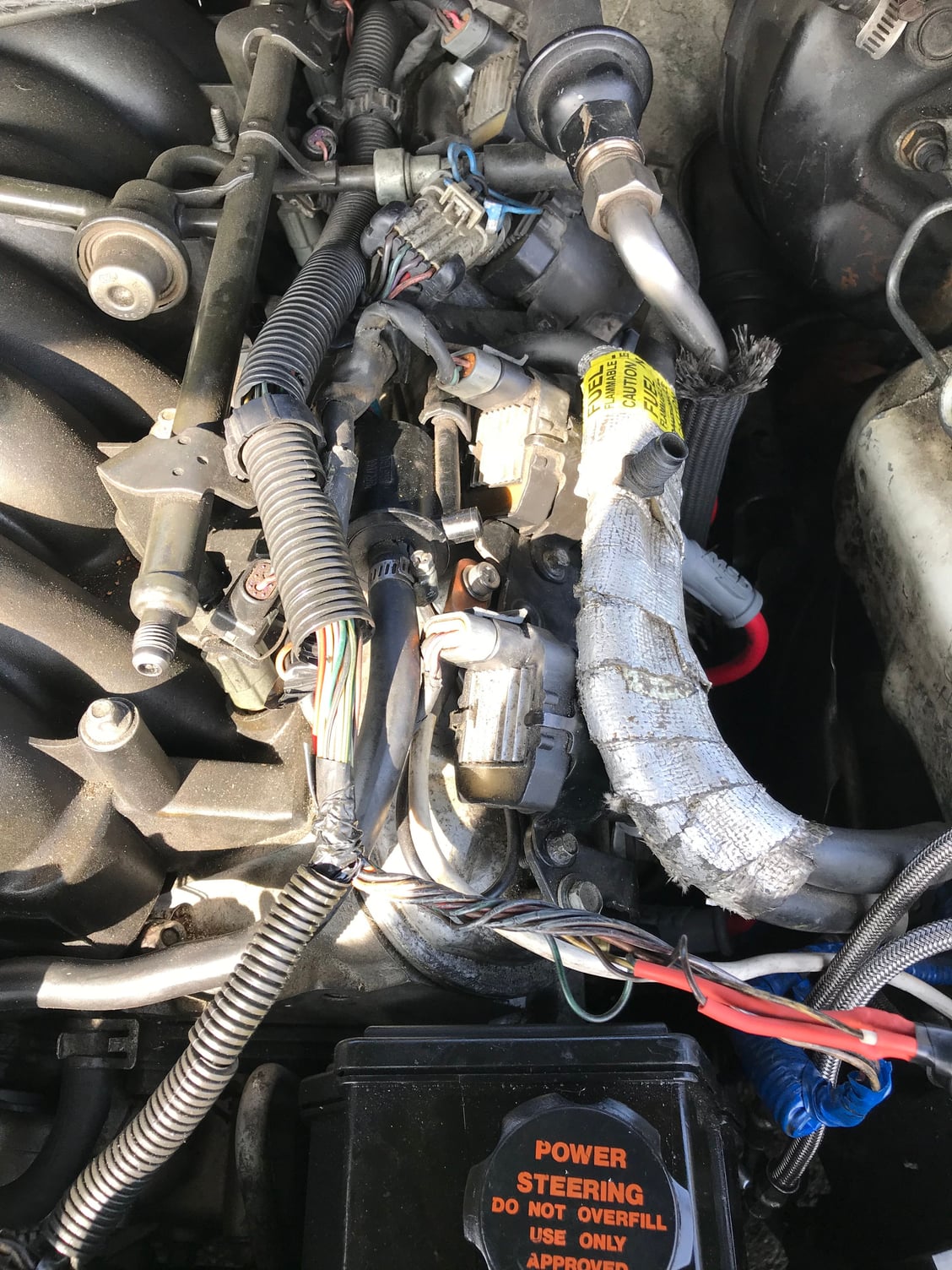
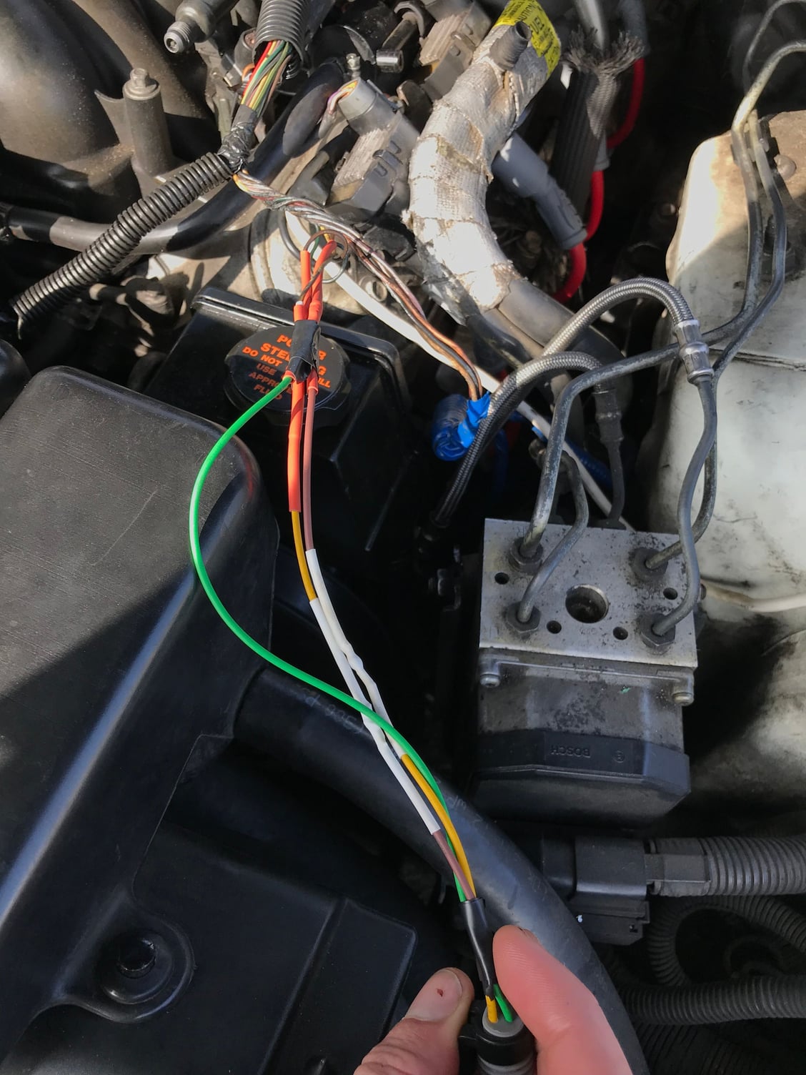
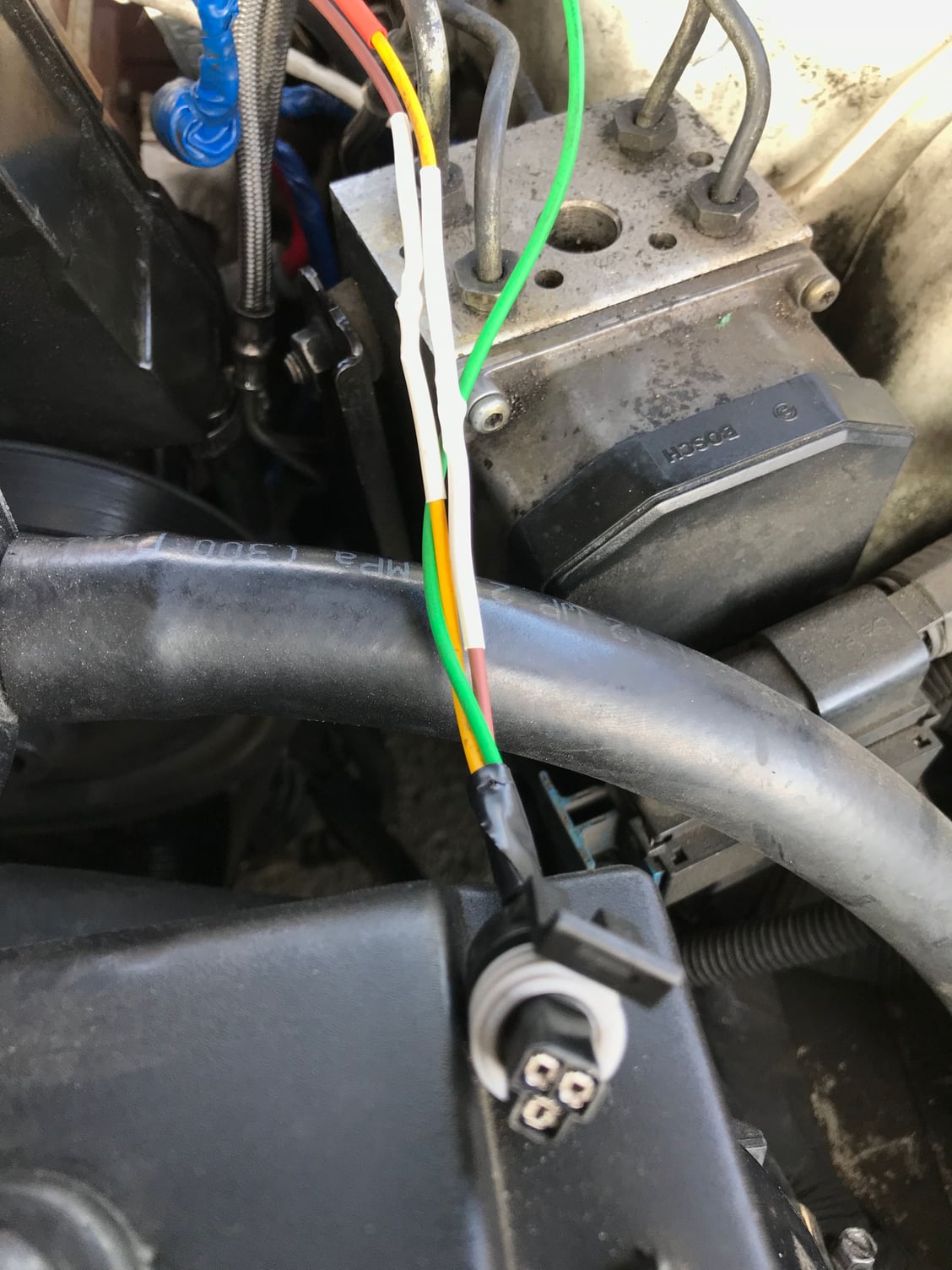
P0301, p0117, p1258
#21
Staging Lane
Thread Starter
Join Date: Jan 2018
Location: Inland Empire, CA
Posts: 77
Likes: 0
Received 0 Likes
on
0 Posts
#22
The rough idle and fans coming on indicate the yellow wire to the PCM is not grounded and working properly. The gage staying on hot points to dark green wire grounded somewhere between the sensor and the gage.
#23
Staging Lane
Thread Starter
Join Date: Jan 2018
Location: Inland Empire, CA
Posts: 77
Likes: 0
Received 0 Likes
on
0 Posts
so is it possible that the wires are shorting somewhere between the sensor and the bigger wire loom? Or a poor connection from the new pigtail I installed?
#24
The only way the pigtail installation could affect the gage is if the dark green wire somehow came into contact with the brown wire of the harness or a grounded metal part. That said, did you verify that the pin connection of the new connector matches the schematic posted in the previous post #8?
#28
Teching In
Join Date: Mar 2018
Location: McKinney, TX
Posts: 27
Likes: 0
Received 0 Likes
on
0 Posts
I don’t think the original sensor was bad, and I doubt you have 2 bad sensors. It’s pretty easy to check the resistance of the temp sensors with a multimeter. I would be checking the temp sensor function by turning the key on, but not necessarily starting the vehicle until you have a better handle on what’s going on. Everything still points to a wiring issue...some pictures might help. I don’t think we ever heard what caused the damage in the first place...might help us identify the possible extent of the damage. If it was rodent damage or melted wires from shorting or from exhaust, etc.
also so the wires can be quickly checked for most issues with a multimeter if you unplug both ends of the wire.
Start by by posting some pics. Pics of the repair, the diagram your looking at, etc so we can see where your coming from.
also so the wires can be quickly checked for most issues with a multimeter if you unplug both ends of the wire.
Start by by posting some pics. Pics of the repair, the diagram your looking at, etc so we can see where your coming from.
#29
Staging Lane
Thread Starter
Join Date: Jan 2018
Location: Inland Empire, CA
Posts: 77
Likes: 0
Received 0 Likes
on
0 Posts
I donít think the original sensor was bad, and I doubt you have 2 bad sensors. Itís pretty easy to check the resistance of the temp sensors with a multimeter. I would be checking the temp sensor function by turning the key on, but not necessarily starting the vehicle until you have a better handle on whatís going on. Everything still points to a wiring issue...some pictures might help. I donít think we ever heard what caused the damage in the first place...might help us identify the possible extent of the damage. If it was rodent damage or melted wires from shorting or from exhaust, etc.
also so the wires can be quickly checked for most issues with a multimeter if you unplug both ends of the wire.
Start by by posting some pics. Pics of the repair, the diagram your looking at, etc so we can see where your coming from.
also so the wires can be quickly checked for most issues with a multimeter if you unplug both ends of the wire.
Start by by posting some pics. Pics of the repair, the diagram your looking at, etc so we can see where your coming from.
#31
I'm like Tayj6, I doubt the sensor is bad. The Check Gages Light coming on is most likely because the dark green wire has come in contact with a ground causing the gage to read above 244*. Take a meter or continuity tester and check for continuity between the dark green wire in the connector and a known ground. If you have continuity, the wire is grounded somewhere between the connector and the gage and will have to be repaired. This would be the only explanation for why the gage would read hot with the connector unplugged from the sensor unless there is a problem in the gage cluster. I've attached a troubleshooting chart that may help.
To check the PCM signal, you should have 5VDC between the yellow and brown wires with the ignition on, engine not running. If not, check between the yellow wire and a ground. No voltage could indicate a broken wire or problem within the PCM.
I've assumed in the past, but feel I should ask, did you bleed the cooling system after replacing the temp sensor. An air pocket could cause incorrect temp readings.
Last edited by wssix99; 03-25-2018 at 09:09 AM. Reason: removed copywritten attachement
#32
Staging Lane
Thread Starter
Join Date: Jan 2018
Location: Inland Empire, CA
Posts: 77
Likes: 0
Received 0 Likes
on
0 Posts
Thank you! And no I did not bleed the system. Tomorrow Iíll put a meter on it. When looking at the diagram it shows the yellow pin on the left hand side. I assumed this was looking into the connector but itís looking into the sensor. May just have some wires mixed up. Still a noob
#33
I've always thought the diagram view was looking into the connector (the pin end). I've attached the service manual explanation.
Last edited by wssix99; 03-25-2018 at 09:08 AM. Reason: removed copywritten attachement
#34
Staging Lane
Thread Starter
Join Date: Jan 2018
Location: Inland Empire, CA
Posts: 77
Likes: 0
Received 0 Likes
on
0 Posts
When looking at the wiring layout I have a 98 so I look at the picture that says engine coolant temperature sensor. But then again it shows the little tab that is on the pigtail
Last edited by Dylanlars; 03-25-2018 at 04:56 AM.
#37
Save the manuals!
iTrader: (5)
Check out the Schematic and Link above. You should ignore the colors on your pigtail at this point.
Make sure the BROWN wire (from the engine harness) gets to the "A" terminal on the plug and the YELLOW wire (from the engine harness) gets to the "B" terminal on the plug. "A" and "B" are noted on the schematic and are also molded into the top of the plug, on the tang that snaps onto the sensor.
If "A" and "B" are correct to the sensor, you are wired correctly.
#39
Staging Lane
Thread Starter
Join Date: Jan 2018
Location: Inland Empire, CA
Posts: 77
Likes: 0
Received 0 Likes
on
0 Posts
Check out the Schematic and Link above. You should ignore the colors on your pigtail at this point.
Make sure the BROWN wire (from the engine harness) gets to the "A" terminal on the plug and the YELLOW wire (from the engine harness) gets to the "B" terminal on the plug. "A" and "B" are noted on the schematic and are also molded into the top of the plug, on the tang that snaps onto the sensor.
If "A" and "B" are correct to the sensor, you are wired correctly.
Make sure the BROWN wire (from the engine harness) gets to the "A" terminal on the plug and the YELLOW wire (from the engine harness) gets to the "B" terminal on the plug. "A" and "B" are noted on the schematic and are also molded into the top of the plug, on the tang that snaps onto the sensor.
If "A" and "B" are correct to the sensor, you are wired correctly.
#40
Staging Lane
Thread Starter
Join Date: Jan 2018
Location: Inland Empire, CA
Posts: 77
Likes: 0
Received 0 Likes
on
0 Posts
Havenít changed the wiring. Went to autozone and picked up an AC Delco sensor and the gauge is sitting pretty at 210 after 4 cycles of starting. I think a combination of damaged wiring (due to changing my spark plugs) and crappy BWD sensor. Problem seems to be gone!


