When you click on links to various merchants on this site and make a purchase, this can result in this site earning a commission. Affiliate programs and affiliations include, but are not limited to, the eBay Partner Network.
C0266 ABS CODE & "ASR OFF" on engine start & can't turn ASR on but ABS WORKS FINE!
So I've been trying to figure out whats wrong with my ASR/TCS system on my 1999 camaro z28 for 2 months now with no luck at all.
I have checked my TPS sensor for clean voltage sweeps from 0 to 100% WOT and it tests perfect. (have not tried to replace it yet).
my elm327 bluetooth scanner connected to my android with the chevrosys app shows C0266 ADS circuit malfunction / ?EBTCM relay? trouble code.
I've seen the ABS/SRS blues thread and I have run through the diagnostic procedure mentioned for the 5.7L camaro as follows:
TEST ASR/TC INDICATOR ALWAYS ON:
DISCONNECT ASR SWITCH, with ignition off, measure from ASR switch terminal E to ground, if infinite resistance replace EBTCM, if resistance is NOT infinite but the indicator is always ON repair short to ground in brown/white wire between ASR switch and the EBTCM.
(I have 4.4 ohms key off between terminal E brown/white wire on the ASR switch and ground, HOWEVER, when I unplug the ebtcm main delphi connector under the hood and check again it's an open line! almost hinting like the supposed short to ground on the brown/white wire is happening INSIDE the ebtcm? or am I just tripping on this? ALSO, with the ASR switch unplugged on the dash and back probing the brown white wire terminal #17 on the abs Delphi connector (because I don't have the fancy breakout box the diagnostic calls for) testing ohms to ground with the key off I get 2.85 ohms resistance, if i keep the meter touching and unplug the delphi connector I get open line! so what is going on here?
I already opened up the EBTCM and soldered all the relays (looked like they were tig welded) and checked over the entire circuit board (had to saw it open first) with my soldering microscope ( I am an electronics repair man by trade) I don't see any issues on the ebtcm circuit board at all and I know what to look for on this specific ebtcm unit!
I also followed the diagnostic procedure specific for the C0266 trouble code (as follows):
DTC C0266: ADS CONTROLLER MALFUNCTION (CAMARO & FIREBIRD)
Circuit Description
This circuit monitors DELIVERED THROTTLE POSITION input for
proper operation.
DTC sets anytime ignition is on and EBCM does not receive a
DELIVERED THROTTLE POSITION input.
Diagnosis
1) Perform DIAGNOSTIC SYSTEM CHECK under DIAGNOSIS & TESTING.
Go to next step.
2) Turn ignition off. Disconnect and check Accelerator and
Servo control Module (ASM) and connector for corrosion or damage. If
connector is faulty, go to step 7). If connector is okay, go to next
step. (CONNECTOR WAS OK)
3) Measure resistance between ASM connector terminal No. 28
(Black/White wire) and ground. If resistance is 0-5 ohms, go to next
step. If resistance is not 0-5 ohms, go to step 8). (RESISTANCE WAS 0-5 OHMS)
4) Measure resistance between ASM connector terminal No. 55
(Black/White wire) and ground. If resistance is 0-5 ohms, go to next
step. If resistance is not 0-5 ohms, go to step 8). (RESISTANCE WAS 0-5 OHMS)
5) Turn ignition on, engine off. Using DVOM, measure voltage
between ASM harness connector terminals No. 1 (Pink wire) and No. 28
(Black/White wire). If voltage is equal to battery voltage, go to step
10). If voltage is not equal to battery voltage, go to next step. (THESE INSTRUCTIONS ARE A BIT TRICKY TO FOLLOW HERE, BUT VOLTAGE WAS 11.89 VOLTS AKA 'CLOSE ENOUGH' so onto step 10)
6) Repair open or high resistance in Pink wire between ASM
and engine wiring harness junction block 2. After repairs, go to step
16).
7) Repair ASM connector as necessary. After repairs, go to
step 16).
8) Repair open or high resistance in Black/White wire between
ASM and ground. After repairs, go to step 16).
9) Replace ASM. See
ACCELERATOR & SERVO CONTROL MODULE (CAMARO & FIREBIRD) under REMOVAL &
INSTALLATION. After repairs, go to step 16).
10) Turn ignition off. Disconnect EBCM connector. Install
Universal Pinout Box (J 39700) using Cable Adapter (J 39700-25) to
EBCM harness connector only. Measure resistance between terminals No.
9 (Tan/Black wire) and No. 15 (Black wire). If resistance is infinite,
go to step 12). If resistance is not infinite, go to next step. (I HAD TO BACKPROBE WITH PINS AS I DONT HAVE THE BREAKOUT BOX, RESISTANCE WAS NOT INFINITE)
11) Repair short to ground in Tan/Black wire between ASM and
EBCM. After repairs, go to step 16). (ITS TELLING ME I HAVE A SHORT TO GROUND BETWEEN TAN AND BLACK WIRE AND GROUND BETWEEN THE CRUISE CONTROL MODULE AND EBTCM?!?!?!)
12) Measure resistance between universal pinout box terminal
No. 9 (Tan/Black wire) and ASM connector terminal No. 35 (Tan/Black
wire). If resistance is 0-5 ohms, go to step 14). If resistance is not
0-5 ohms, go to next step.
13) Repair open or high resistance in Tan/Black wire between
ASM and EBCM. After repairs, go to step 16).
14) Turn ignition on, engine off. Using DVOM, measure voltage
at universal pinout box terminal No. 9 (Tan/Black wire). If voltage is
greater than one volt, go to next step. If voltage is not greater than
one volt, go to step 9).
15) Repair short to voltage in Tan/Black wire between ASM and
EBCM. After repairs, go to next step.
16) Using scan tool, clear DTCs. Operate vehicle. If DTC does
not reset, system is okay.
Diagnostic Aids
A thorough inspection of wiring and connectors is important
to prevent misdiagnosis. Check for backed-out terminals, improper
mating, broken locks, improperly formed or damaged terminals, poor
terminal-to-wiring connections, or damaged wiring harness. An
intermittent may be caused by a poor connection, rubbed-through wire
insulation, or a broken wire inside insulation.
Heres the kicker, after following that diagnostic procedure and having it tell me theres a short to ground on the tan/black wire, I go under the dash and unplug the cruise control module and no longer see a connection/continuity between the tan and black wire and ground? what does this mean?! does this hint that the cruise control module is bad or what?
I'm really lost at this point, and I'm going to keep bugging people until I get it solved! please help me!
Gary M
PS. FORGOT TO MENTION CRUISE CONTROL WORKS FINE AS FAR AS SETTING SPEED AND IT MAINTAINING THAT SPEED. ABS SEEMS TO WORK FINE BUT I DONT KNOW HOW TO PROPERLY TEST IT? PEOPLE SAY I SHOULD FEEL A FAST PULSING ON THE BRAKE PEDAL WHEN I SLAM ON IT FROM A FAST SPEED? BUT I DONT FEEL THAT? IF I SLAM HARD ENOUGH THE "LOW TRAC" LIGHT COMES ON BUT THE BRAKE INOP LIGHT NEVER COMES ON AND THE ABS ERROR LIGHT NEVER COMES ON? SO I ASSUME THIS MEANS MY ABS IS WORKING? IF I UNPLUG BOTH EBTCM ELECTRICAL CONNECTORS TEH BRAKE INOP LIGHT DOES SHOW UP ON THE DASH, WHEN I PLUG IT BACK IN THE BRAKE INOP LIGHT GOES AWAY.
Last edited by Gary Maurizi; 12-06-2018 at 06:49 AM.
if I back probe the throttle position sensor signal wire and test the voltage while very very slowly moving the throttle from 0% to 100% and see a perfectly smooth climb from .60 to 4.30 volts even while tapping on the TPS does this verify that the actual TPS sensor is 100% good no questions? or does this only test the wiring/signal sent to the TPS from the throttle and not the TPS itself?
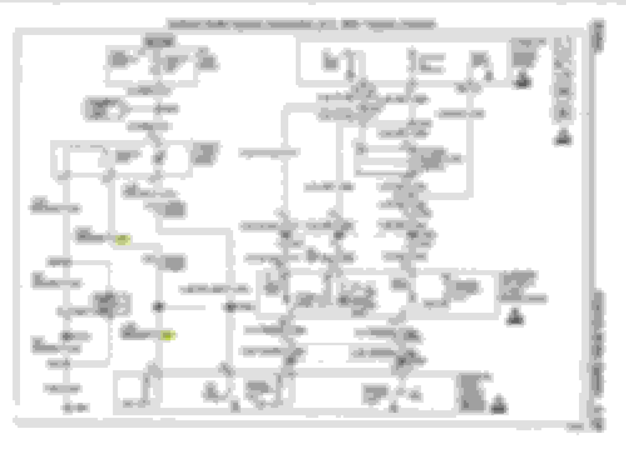
because I'm looking at the helms schematics for this circuit on page 5-109 and I see the tan/black wire that the diagnostics procedures above told me where shorted to ground? that tan/black wire seems to connect straight to the throttle position sensor (delivered TP position output) via the ASM/cruise control module? I don't really understand the rest of this circuit fully to diagnose further...
DTC C0266: ADS CONTROLLER MALFUNCTION (CAMARO & FIREBIRD)
Circuit Description
This circuit monitors DELIVERED THROTTLE POSITION input for
proper operation.
DTC sets anytime ignition is on and EBCM does not receive a
DELIVERED THROTTLE POSITION input.
If I am reading the circuit diagram correctly on page 5-109, the ASM cruise control module ACTUALLY DOES GROUND the tan and black wire? so wtf? why does the diagnostic procedure say they should not be connected?!?!
also the schematic shows that the brown and white wire should ONLY touch ground momentarily WHEN you switch ASR on or off?! but the diagnostic procedure from the ABS/SRS blues thread PDF document says that "if resistance is infinite replace the ebtcm?"
Am i missing something or does all of this information conflict?
How is it that almost no one understands this damned TCS system? this has just gotten ridiculous for me at this point! sigh.
HELP!
Last edited by Gary Maurizi; 12-06-2018 at 06:36 AM.
I have now officially replaced the TPS throttle position sensor and the issue still remains.
I did both versions of the TPS relearn procedure (engine off, and engine on/unplug) and I did the IAC relearn procedure whatever that is.
Still defaults to "asr off" when i start the engine and the switch does nothing.
PLEASE someone put me out of my misery here and at least give me a hint?
At this point its like my only options left are to replace the EBCM and the servo control module, but I cant find a replacement ebcm ANYHERE? only services that rebuild them? I already cut mine open looking for the common fault and glued it back together with jb-weld, what are the chances an ebcm repair service will still take my ebcm even after its been cut open and reglued already?
THE LIGHT INSIDE THE ASR SWITCH ON THE DASH ACTUALLY FLASHES TWO TIMES QUICKLY THEN GOES OUT WHEN I TURN THE KEY TO THE ON POSITION, IS THIS NORMAL? THE ASR OFF LIGHT ON THE INSTRUMENT PANEL LIGHTS UP IMMEDIATELY ALSO.
I swear to god, ONE guy at GM designed this terrible TCS/Cruise system circuitry, put up invalid circuit diagrams to troll us all, and then died a decade ago. fml.
Still no progress, after another day of testing and fiddling.
I purchased a tech II clone tool to read the ABS codes and program a new ABS module when it arrives in the mail (purchased from ebay).
I can't figure out how people are saying these bosch motronics ABS modules need to be programed to the cars vin? i dont see anything in the tech 2 thats hints towards programming the abs module to the VIN?
I did figure out that 1) my switch works. 2) my ABS is actually off even though the brake inop light is NOT lit (only light is ASR OFF lit up), and the TCS is obviously off.
Heres some photos from the tech 2 tool... now i just need to figure out how to use this tool to diagnose my TCS issue.
I replaced the EBTCM brake computer module today and re-examined a bunch of stuff.
I re-ran the ABS system diagnostic for code c0266 (ADS circuit malfunction) and ended up on step 14 where it checks the brown and tan wire on the EBTCM wire harness for voltage. The tan and black wire had 8-10 volts, and the diagnostic procedure says "if it has over 1 volt repair the short to ground".
I go under the dash and unplug c220 (the plug that connects the cruise control & servo control module to the ebtcm brake computer) and the voltage disappears, I think this is insinuating that I had it wrong and its actually a faulty cruise control & servo control module and not a faulty ebtcm brake computer?
I drove for about 10 miles and got a new code C0240 (PCM traction control not allowed) and the BRAKE INOP and red BRAKE lights lit up on the dash and are still lit.
Sorry to see you are having so much trouble, the TCS system is worthless crap to start with then add a single fault and its loony bin. With a car this old 1st thing I would do is check all your grounds and connections in the entire system. Sorry I can't help more.
Sorry to see you are having so much trouble, the TCS system is worthless crap to start with then add a single fault and its loony bin. With a car this old 1st thing I would do is check all your grounds and connections in the entire system. Sorry I can't help more.
Thanks! Yeah I feel yah.
I've already gone through all of the grounds.
I found another user on another camaro z28 specific forum that had the same EXACT issue as me (the tan/white wire touching to ground between the ebtcm and the throttle position module under the dash) so this leads me to think that this is actually a bad module or a bad eletronic part, and NOT just a wiring fluke where for example a grommet rubbed through via vibration and shorted a wire to chassis (these types of wiring flukes are one in a million usually, so to find two people with the same wiring fluke is NOT likely).
I've already replaced the ebtcm with one from ebay (though its possible it is ALSO bad? I don't think it is) and still getting the same error codes -- except now after replacing the ebtcm my ABS INOP and red BRAKE lights are on along with the ASR OFF light.
I have a new throttle position module (also known as servo control module) on the way from ebay -- I believe that it is the cause of this specific issue -- when I have the white harness for it (the throttle module under the dash) unplugged the voltage on the tan and white wire goes from 10 dcv down to 1 dcv (its supposed to be 1 volt or less according to the diagnostic procedures in the ABS thread).
Keeping my fingers crossed.
If this new throttle position module does not fix the problem, I'm going to believe I actually either got a second bad ebtcm from ebay or I actually do have a fluke wiring fault shorting that tan and white wire to ground.
I'll keep this thread updated, not enough people see their forum threads through to the solution, so the next person with this issue has an answer. That's assuming I ever figure it out.
Maybe call around your area GM dealers, might find some help there. I'm glad my WS6 doesn't have it. I owned quite few cars that did, as far as I'm concerned its dangerous system. A few times pulling out into traffic it would thump the gas pedal then the car just stopped moving. I always turned it off after that. If you think yours is bad you should see the drive by wire 99-02 V6 systems, complete insanity that even the dealers couldn't figure out. I know of someone who bought one that the dealer couldn't fix, it stayed in some kind of limp mode.
Thanks man for the moral support and just talking to me!
I actually got it fixed, popped in the new throttle position controller just now and the ASR switch lit up started working like good as new!
I wish I had seen the letters "ADS" on the throttle position controller module under the dash, and I would have known what the problem is MUCH earlier.
C0266 code was "ADS circuit malfunction".. but no one anywhere called the damn thing an ADS... people called it a servo module, a cruise control module, a throttle position module, but not ONCE did anyone refer to it as "ADS" lol.
Sigh.
Now fingers crossed the red brake warning light and ABS inop lights dont turn back on when I make a sudden stop. Ill post back.
small wins in the larger war.
ADDENDUM: the switch is "appearing to work like new" , in the tech 2 tool I see when the switch turns on and off, however when the switch is turned on, the tech 2 tool still says "tcs off" and "abs off" even though there are NO codes on any modules after driving and slamming on the brakes...
I'm hopping I just have to do a 'drive cycle' to run all the readiness tests.
2ND ADDENDUM: the ebay ebtcm was giving me trouble, in other threads people say they had to take their cars to the dealership to when they changed ebtcm's because they had to reprogram the old ebtcm to the VIN number of the car its now in. Yet I don't see a SINGLE PLACE ANYWHERE in a tech 2 tool to program an ebtcm module for a 1999 camaro... stealership lie and they were just clearing abs code? or maybe my clone tech 2 tool is missing something? the SPS programming menu on my clone tool is off limits, possibly in there.
Last edited by Gary Maurizi; 12-17-2018 at 08:20 PM.
 12-06-2018, 05:52 AM