


My 347ci build
Well tonight was yet another one step forward one step back kind of night...nature of the beast I suppose.
I deburred my cam bearings - Durabond CHP-10's - used my bearing knife to chamfer all the oil holes and get rid of any extra coating material, took 1000 grit to the areas immediately surrounding the holes because there's usually high spots there, smoothed all the chamfers on the ID to aid cam installation, then took it to the chamfers on the OD to make bearing installation easier. Ideally this shouldn't be necessary but the bearings themselves were pretty sloppy out of the box, to be honest.
Installed the bearings with loctite 640, lined up the oil holes, inserted the cam and it spun without binding. I felt like it was too good to be true....and it was.
Oil clearances (cam mic'd at 2.1660" give or take a tenth or two, wasn't **** about it right now because I just wanted a ball park)
1: 0.0023"
2: 0.0035"
3: 0.0035"
4: 0.0032"
5: 0.0032"
My initial reaction to this is that my clearances are way too big - not good for oil pressure. I'll be damned if I compromise now after all the time I took setting up the mains. Any input is welcome.
Last edited by ckpitt55; Jun 14, 2013 at 07:29 AM.
TECH Fanatic

Joined: Jun 2011
Posts: 1,343
Likes: 8
From: Katy, TX
I'd run it, those numbers look perfect to me. I've got up to 0.006" on my iron block, and I still get 60 psi at hot idle with 0-40w M1 oil.
See post #11, this is a solid source:
https://ls1tech.com/forums/generatio...d-replace.html
See post #11, this is a solid source:
https://ls1tech.com/forums/generatio...d-replace.html
0.003", fair enough...guess I will run it. Thanks man. Out of curiosity who was that making that post (racer7088)?
I asked Tony about it also and he said it was more of a "feel" thing than strict clearance windows, seems to align with that. The cam definitely feels good though - I can spin it easily by hand by grabbing the dowel, no binding or tight spots.
Checked my cam clearances tonight a bit more thoroughly and ended up with pretty much the same numbers I posted earlier. Based on how it feels and the feedback I've gotten I'm just going to run it.
Also pulled out the connecting rods and looked at the bearing clearances. With the standard P bearings I installed a while ago, I was seeing between 0.0026-0.0027" on the whole set - too loose.
With mixed H bearings - 0.001" upper and a standard lower, I got down around 0.0024". Still too loose.
With a full 0.001" undersize H set, I ended up with 0.0019". About right. I only did my experiments with 1 rod but expect the trend to carry to the rest of them given that I didn't see much variation.
TECH Fanatic
Joined: Jun 2011
Posts: 1,343
Likes: 8
From: Katy, TX
0.001-0.006" spec window lol, engine building's equivalent of a country mile
0.003", fair enough...guess I will run it. Thanks man. Out of curiosity who was that making that post (racer7088)?
I asked Tony about it also and he said it was more of a "feel" thing than strict clearance windows, seems to align with that. The cam definitely feels good though - I can spin it easily by hand by grabbing the dowel, no binding or tight spots.
1. less forces on the camshaft vs. the crank and rods.
2. forces exerted on the camshaft (lifters) are only in one direction and keep the cam "planted" in the same spot.
3. there is only one small oiling hole on each cam bearing, more of a restriction for the oil to flow.
racer7088 is Erik, owner of HKE
http://www.hkracingengines.com/packages_ls1.php
Also pulled out the connecting rods and looked at the bearing clearances. With the standard P bearings I installed a while ago, I was seeing between 0.0026-0.0027" on the whole set - too loose.
With mixed H bearings - 0.001" upper and a standard lower, I got down around 0.0024". Still too loose.
With a full 0.001" undersize H set, I ended up with 0.0019". About right. I only did my experiments with 1 rod but expect the trend to carry to the rest of them given that I didn't see much variation.
0.0026" - for "high performance engines" from Clevite catalog EB-10-07
0.0020" - 0.0025": Potak's book, p. 40
Also, according to the "dimensions and clearances" sticky, the OEM LS1 clearance window is 0.0006" - 0.00248"
FYI, I'm running 0.0025 - 0.0028" on mine with H bearings. However I know a lot of people run tighter (0.0018 ish) and they don't have any problems. Mostly just a preference thing I guess.
Have you played around with measuring the rod bolt stretch yet?

"Too loose, and only you know it. Too tight, and everyone knows it"
If your bearing clearances are too loose, all it will do is decrease oil pressure, but too tight, and you can be chunking parts out of the oil pan. I am at about .0025" on my cam journals and mains, and about .022" on the rods (.003" without the coating). With the M10296 pump and blue spring, I see no less than 35psi at hot idle.
If your bearing clearances are too loose, all it will do is decrease oil pressure, but too tight, and you can be chunking parts out of the oil pan. I am at about .0025" on my cam journals and mains, and about .022" on the rods (.003" without the coating). With the M10296 pump and blue spring, I see no less than 35psi at hot idle.
I'm not totally sure why we can get by with more clearance on the cam bearings, however I have a few theories:
1. less forces on the camshaft vs. the crank and rods.
2. forces exerted on the camshaft (lifters) are only in one direction and keep the cam "planted" in the same spot.
3. there is only one small oiling hole on each cam bearing, more of a restriction for the oil to flow.
racer7088 is Erik, owner of HKE
http://www.hkracingengines.com/packages_ls1.php
here are a couple sources I used when doing my rods:
0.0026" - for "high performance engines" from Clevite catalog EB-10-07
0.0020" - 0.0025": Potak's book, p. 40
Also, according to the "dimensions and clearances" sticky, the OEM LS1 clearance window is 0.0006" - 0.00248"
FYI, I'm running 0.0025 - 0.0028" on mine with H bearings. However I know a lot of people run tighter (0.0018 ish) and they don't have any problems. Mostly just a preference thing I guess.
Have you played around with measuring the rod bolt stretch yet?
I think I would be more hesitant to run the tighter clearance if my journals had more o-o-R. I mic'd them with 0.0001" or less o-o-R and taper, which is as good as I could hope to measure. So I'd call it +/- 0.0001" for each taking accuracy / repeatability into account.
"Too loose, and only you know it. Too tight, and everyone knows it"
If your bearing clearances are too loose, all it will do is decrease oil pressure, but too tight, and you can be chunking parts out of the oil pan. I am at about .0025" on my cam journals and mains, and about .022" on the rods (.003" without the coating). With the M10296 pump and blue spring, I see no less than 35psi at hot idle.
If your bearing clearances are too loose, all it will do is decrease oil pressure, but too tight, and you can be chunking parts out of the oil pan. I am at about .0025" on my cam journals and mains, and about .022" on the rods (.003" without the coating). With the M10296 pump and blue spring, I see no less than 35psi at hot idle.
I'm at 0.0020" for mains (target 0.0017-0.0020")
0.0035" for cam - coated bearings
0.0019" for rods (target 0.0018-0.0022")
I'd expect the mains and cam clearances to be more sensitive due to the different expansion rates...with the rods, steel on steel it's not as much of an issue. The crank journals and rod bores are very round.
I've been working towards what Tony's recommendations were for each.. my target specs were considerably looser than what the shop was content setting it at. Prior to all the mains work I did, the shop had them set with 0.001 undersize H's with 0.0012-0.0015" of clearance.
Thanks for any input guys
-Chuck
Last edited by ckpitt55; Jun 15, 2013 at 11:21 AM.
LS1 Tech Stories
The Best V8 Stories One Small Block at Time

Amazing '71 Camaro Restomod Is Modern Muscle Car Under the Skin
Verdad Gallardo
6 Common C5 Corvette Failures and What's Involved In Repairing Them
Pouria Savadkouei
Retro Modern Bandit Pontiac Trans AM Comes With Burt Reynolds' Autograph
Verdad Gallardo
Top 10 Greatest Cadillac V Series Performance Models Ever, Ranked
Pouria Savadkouei
Top 10 Most Powerful Chevy Trucks Ever Made!

Hennessey's New Supercharged Silverado ZR2 Has 700 HP
Verdad Gallardo
Coachbuilt N2A Anteros Is an LS2-Powered C6 Corvette In Italian Clothes
Verdad Gallardo
Awesome K5 Blazer Restomod Comes With C7 Corvette Power
Verdad Gallardo
10 Camaros You Should Never Buy
Agreed...do my clearances seem too tight to you?
I'm at 0.0020" for mains (target 0.0017-0.0020")
0.0035" for cam - coated bearings
0.0019" for rods (target 0.0018-0.0022")
I'd expect the mains and cam clearances to be more sensitive due to the different expansion rates...with the rods, steel on steel it's not as much of an issue. The crank journals and rod bores are very round.
I've been working towards what Tony's recommendations were for each.. my target specs were considerably looser than what the shop was content setting it at. Prior to all the mains work I did, the shop had them set with 0.001 undersize H's with 0.0012-0.0015" of clearance.
Thanks for any input guys
-Chuck
I just found a rocker bearing scattered in my engine, so it looks like time for another build thread from me as well. Lol
Lmfao.
Yeah, they look fine for what you're doing. I've seen stock LS stuff run as little as .0009" bearing clearance, so doubling that would be okay for most mild NA builds.
I just found a rocker bearing scattered in my engine, so it looks like time for another build thread from me as well. Lol
I just found a rocker bearing scattered in my engine, so it looks like time for another build thread from me as well. Lol
Sorry to hear that, looking forward to a build thread though. Time to make it bigger and badder
Lol
Last edited by ckpitt55; Jun 26, 2013 at 02:38 PM.
Got the rods all torqued up and measured. 75 ft-lbs gave me my desired 0.004-0.005" of stretch across the board - I was around 0.0045" on every one. Clearance range goes from 0.0017 - 0.0019", might have to do some shuffling around to match the smaller bores up with the smaller journals.
I've got my heads torqued on and I'm about to measure my cylinder bores from the bottom of the block. Prelim measurements last night showed that the second shop (LAW Engines) did a pretty damn good job - saw 2 tenths or less taper and o-o-R in pretty much all the bores. Gonna go back through and do more thorough measurements tonight here.
Does anyone have experience with Total Seal plasma moly rings? Why is it that they spec a tighter second ring gap than the top ring? This is contrary to anything I've ever read - running a tighter second gap increases the likelihood of ring flutter / unseating of the top ring, no?
slowly making progress, a few more parts rolling in. ati damper 917276 and 100mm maf housing from texas speed with the ls7 sensor. wasn't aware of this when ordering but the ls7 has a 5 pin output that combines iat with maf readings, which brings about the need for the pigtail adapter for use with an ls1 harness. pinouts below for anyone who needs em


Measured up the cylinder bores after the second machining op. Looks to be about as good as they're going to get.

After talking with Tony i'll be setting the rings up for 0.018-0.020" top, 0.023-0.024" second.
My "setup". I use the stone to knock burrs off the rings before putting them in the block to check fitment.

ring squaring tool - ensures repeatable depth / squareness of the ring with the bores.


Top rings are gapped, just need a bit more fine-deburring before assembly. One bank of the second rings are roughly gapped to fit the bore - need more filing to bring them to where I want them.

Hope to start putting her together this weekend
Measured up the cylinder bores after the second machining op. Looks to be about as good as they're going to get.
After talking with Tony i'll be setting the rings up for 0.018-0.020" top, 0.023-0.024" second.
My "setup". I use the stone to knock burrs off the rings before putting them in the block to check fitment.
ring squaring tool - ensures repeatable depth / squareness of the ring with the bores.
Top rings are gapped, just need a bit more fine-deburring before assembly. One bank of the second rings are roughly gapped to fit the bore - need more filing to bring them to where I want them.
Hope to start putting her together this weekend
Last edited by ckpitt55; Jun 28, 2013 at 06:57 AM.


Been a busy few days here. Modified a cam bearing driver for a fella on here - the bearing was getting bound up on the tool once it crushed down, so I turned it a few thou and cut o-ring grooves to prevent metal-metal contact.

Finished setting my ring gaps....pretty even across the board, happy with it.

Also revisited my rod bearing clearances. Opted to go a tad looser than I had them originally - I inspected them more thoroughly and realized that the 0.0019" I was originally seeing with the full undersize set was assuming the smallest journal size. More realistically I would have been closer to 0.0016"...a bit too tight. So I matched specific rods to specific journals and experimented with bearing combos until I got them as even as I could. Ended up using mixed bearings (0.001" upper, std lower) to give me 0.0022" +/- 0.0001" across all 8 rods.

Also laid in the crank. Did one last cleaning of the block, installed the front and rear galley plugs, the side galley and coolant plugs, and cleaned the bearings one last time prior to install.


With the crank in I wanted to check out my deck squareness. I did it before with 2 pistons but wanted to check all 4 corners. Looks like there's about a thou of runout on each deck surface. Not perfect but I'm not going to worry about it.


I'm going to wait until I install and degree the cam before I do the final install on the pistons/rods with the rings. No point in adding all that extra friction when I'm trying to make fine adjustments.
There were a couple threads lately about degree wheels....I got the Mr. Gasket one from jegs for 20 bucks. It comes with a centering adapter that fits an M16 stud perfectly. I pieced together my own degree wheel mount / pulley installer with parts from Mcmaster. For the degree wheel, basically just an M16x2.0 stud, tapped plastic ****, and a couple nuts. The **** lets me lock / adjust the degree wheel independently of the crank...maybe not necessary but figured it'd be easier than using the crank bolt.

Waiting on a new cam retainer plate and I'll be able to get the cam installed and degreed. Btw, for anyone looking for the older style cam retainer plate with the non-recessed holes, Rock Auto has them - VICTOR REINZ Part # B31822.
Was going to set my wiper pattern on the rockers last night, but realized I don't have an indicator with enough travel for me to recreate my valve lift. Derp. Waiting on a few more tools, a few more parts, etc. etc. It never ends
Happy 4th everyone


-Chuck
Finished setting my ring gaps....pretty even across the board, happy with it.
Also revisited my rod bearing clearances. Opted to go a tad looser than I had them originally - I inspected them more thoroughly and realized that the 0.0019" I was originally seeing with the full undersize set was assuming the smallest journal size. More realistically I would have been closer to 0.0016"...a bit too tight. So I matched specific rods to specific journals and experimented with bearing combos until I got them as even as I could. Ended up using mixed bearings (0.001" upper, std lower) to give me 0.0022" +/- 0.0001" across all 8 rods.
Also laid in the crank. Did one last cleaning of the block, installed the front and rear galley plugs, the side galley and coolant plugs, and cleaned the bearings one last time prior to install.
With the crank in I wanted to check out my deck squareness. I did it before with 2 pistons but wanted to check all 4 corners. Looks like there's about a thou of runout on each deck surface. Not perfect but I'm not going to worry about it.
I'm going to wait until I install and degree the cam before I do the final install on the pistons/rods with the rings. No point in adding all that extra friction when I'm trying to make fine adjustments.
There were a couple threads lately about degree wheels....I got the Mr. Gasket one from jegs for 20 bucks. It comes with a centering adapter that fits an M16 stud perfectly. I pieced together my own degree wheel mount / pulley installer with parts from Mcmaster. For the degree wheel, basically just an M16x2.0 stud, tapped plastic ****, and a couple nuts. The **** lets me lock / adjust the degree wheel independently of the crank...maybe not necessary but figured it'd be easier than using the crank bolt.
Waiting on a new cam retainer plate and I'll be able to get the cam installed and degreed. Btw, for anyone looking for the older style cam retainer plate with the non-recessed holes, Rock Auto has them - VICTOR REINZ Part # B31822.
Was going to set my wiper pattern on the rockers last night, but realized I don't have an indicator with enough travel for me to recreate my valve lift. Derp. Waiting on a few more tools, a few more parts, etc. etc. It never ends
Happy 4th everyone
-Chuck
Last edited by ckpitt55; Jul 4, 2013 at 02:19 PM.
TECH Fanatic
Joined: Jun 2011
Posts: 1,343
Likes: 8
From: Katy, TX
Happy independence day to you as well! Looks like you're having a great time. I'm enjoying the pictures, keep em coming!
In case you have not done it yet, I have one small suggestion for an additional check - the absolute minimum quench when considering piston rock. Rock the piston by hand and measure the deck height at the edge of the piston. See image below. For my build, there was about 0.015" less quench when considering piston rock at the edge of the piston.
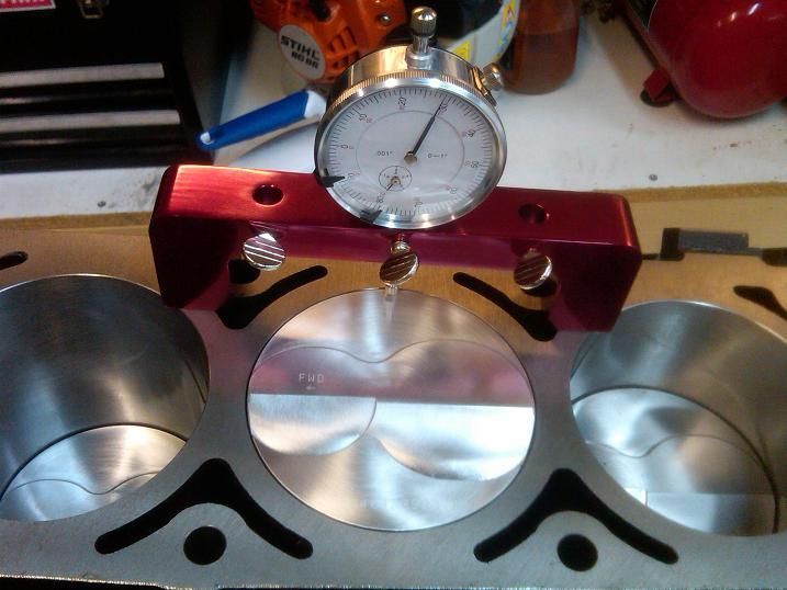
In case you have not done it yet, I have one small suggestion for an additional check - the absolute minimum quench when considering piston rock. Rock the piston by hand and measure the deck height at the edge of the piston. See image below. For my build, there was about 0.015" less quench when considering piston rock at the edge of the piston.


Man, what a thread! This looks like a lot of fun. One of these days I hope to be in a position to do something similar. My '98 is getting close to 160k and it needs a lot of TLC. I'd love to do a rebuild on it. My only thing is that I don't know if a '98 block deserves the amount of meticulous attention that you're giving that newer block. I'm thinking that maybe I could find a donor pickup and get a high mileage iron block to punch out and build in the garage.
I've been collecting books over the last several years on rebuilding an LS engine, and this is a great thread to go along with it. I hope you don't ever move the pictures because I can see a lot of people using this thread in the years to come as a supplemental to their build - broken links suck! You've sort of changed my mind about getting a short block. I think I'd rather build one from scratch and spend some good quality time in the garage focusing on the ten-thousandths!
Did you acquire all of the specialized engine building tools just for this build or did you have most of them laying around? Most folks, myself included, don't have mics, piston ring filers, degree wheels, etc. laying around, and I just wonder if the cost of all the tools would offset the savings and put you past short-block stroker territory.
Several things could come from Harbor Freight, but then again there are probably some tools that you wouldn't want to skimp on either. I suppose if someone never planned on building another engine then they could sell their tools, but then again, I'm into motorcycles and old school hotrods, so maybe I would use them all again.
An LS seems like a scary first build for me, but I suppose if you're as meticulous as you are then it'd be fine. Awesome build man. I can't wait to hear it run and see some dyno numbers!
Thanks for the tip Rezin, I'll be sure to check that out. Did you end up compensating for the piston rock in any way? I always assumed the piston to be square with the heads in the theoretical quench measurement. Besides, how much do the pistons really rock when the engine's up to temperature?
And thanks for the kind words Kurt, it is a lot of fun. Requires a lot of time, patience, (and money) but I'm hoping that the end results will be worth it. As for the tooling - no I didn't have a lick of it when I started. Granted I didn't buy it all at once, I've accumulated them all over the better part of a year. This motor is the first one I've ever laid hands on - diving in head first so to speak lol. It kind of evolved to the full build that it is now - at first all I planned on doing was a cam swap, but figured "while I'm in there.....". Lol. The tooling investment is definitely not insignificant though - but I look at the tools as that - an investment. Instead of paying someone else to do the work, I figured I'd end up with some tools and knowledge that I can carry with me for the rest of my life. Might not be worth the "novelty" to some but if you're a hands-on do-it-yourselfer like me then it might be worth it to you. Much more rewarding than writing a check imo, even if it does take a hell of a lot longer. I've got a "tool list" on page 5, btw.
Philosophy aside, I think LS motors are the perfect motor to dig into - setting them up right requires great attention, but the layout itself is not complicated at all. If you get the opportunity I'd definitely encourage you to dig into it. Hopefully my ramblings on here will be useful to you.
-Chuck
Last edited by ckpitt55; Jul 6, 2013 at 09:35 PM.
TECH Resident
Joined: Jan 2011
Posts: 934
Likes: 0
From: Tulsa
I really just want to say thank you for taking the time and makong the effort to make this tread. I know it takes a lot of patience and reasearch to take pictures and make everything right and I personally appreciate it immensely.
Not a problem my man
Got a few pics from the cam install the other day, still need to properly degree it though.

New cam retainer plate - original style with the flat holes as per mentioned above

Installed with trick flow timing chain dampener, with arp bolts (becomes important in a minute)

It took me a some fiddling around until I realized that you cannot install the timing set with the ls2 dampener installed on the trick flow bracket - there is not enough slack in the chain for the gear to clear the dampener. So you have to install the retainer, then the bracket (less the dampener), install the timing set, then install the dampener last.
BUT, I made a mistake - I got it all together, but had difficulty turning the motor over. Not a tremendous amount of effort, but it didn't feel right. I then realized that I had installed the wrong bolts on the lower 3 holes of the cam retainer plate. With the trick flow bracket, they provide 3 low profile button head screws so that you clear the cam sprocket. I had bought arp retainer plate bolts a while back and forgot to install the ones that came with the trick flow kit - had them under my bench....out of sight, out of mind I guess. A pretty idiotic move, but glad I caught it now.

Make sure you install the right bolts, or you'll do this:

Anyone have any qualms about running the cam sprocket in that state? Given that it didn't occur at load and had maybe 2-3 rotations by hand I'm inclined to run it, honestly.
Got a few pics from the cam install the other day, still need to properly degree it though.
New cam retainer plate - original style with the flat holes as per mentioned above
Installed with trick flow timing chain dampener, with arp bolts (becomes important in a minute)
It took me a some fiddling around until I realized that you cannot install the timing set with the ls2 dampener installed on the trick flow bracket - there is not enough slack in the chain for the gear to clear the dampener. So you have to install the retainer, then the bracket (less the dampener), install the timing set, then install the dampener last.
BUT, I made a mistake - I got it all together, but had difficulty turning the motor over. Not a tremendous amount of effort, but it didn't feel right. I then realized that I had installed the wrong bolts on the lower 3 holes of the cam retainer plate. With the trick flow bracket, they provide 3 low profile button head screws so that you clear the cam sprocket. I had bought arp retainer plate bolts a while back and forgot to install the ones that came with the trick flow kit - had them under my bench....out of sight, out of mind I guess. A pretty idiotic move, but glad I caught it now.
Make sure you install the right bolts, or you'll do this:
Anyone have any qualms about running the cam sprocket in that state? Given that it didn't occur at load and had maybe 2-3 rotations by hand I'm inclined to run it, honestly.
Last edited by ckpitt55; Jul 6, 2013 at 11:58 PM.
TECH Fanatic
Joined: Jun 2011
Posts: 1,343
Likes: 8
From: Katy, TX
Thanks for the tip Rezin, I'll be sure to check that out. Did you end up compensating for the piston rock in any way? I always assumed the piston to be square with the heads in the theoretical quench measurement. Besides, how much do the pistons really rock when the engine's up to temperature?
Build is looking great! You're getting closer! Thanks for sharing all the pics.