When you click on links to various merchants on this site and make a purchase, this can result in this site earning a commission. Affiliate programs and affiliations include, but are not limited to, the eBay Partner Network.
Hi Hero, the crankshaft/pilot bearing/input shaft ALL must match in a length requirement.
The Thrust wear STATES a problem, SO I ASK "what side is the wear front/rear ?
Lance
I understand. I know its not safe to assume, however the same transmission/pilot/clutch TOB was used on this assembly vs the previous. I would have suspected that at this rate, if there was an issue there it would have reared its ugly head much sooner on my previous motor.
Also, I would be surprised if a thrust failure of this nature would have caused the bearing scoring on the #4&5 mains. As any debris/flakes/particles from the thrust surface would have to travel down to the oil pan, then back through the pickup->pump->filter->past every other bearing before reaching 4&5 ??
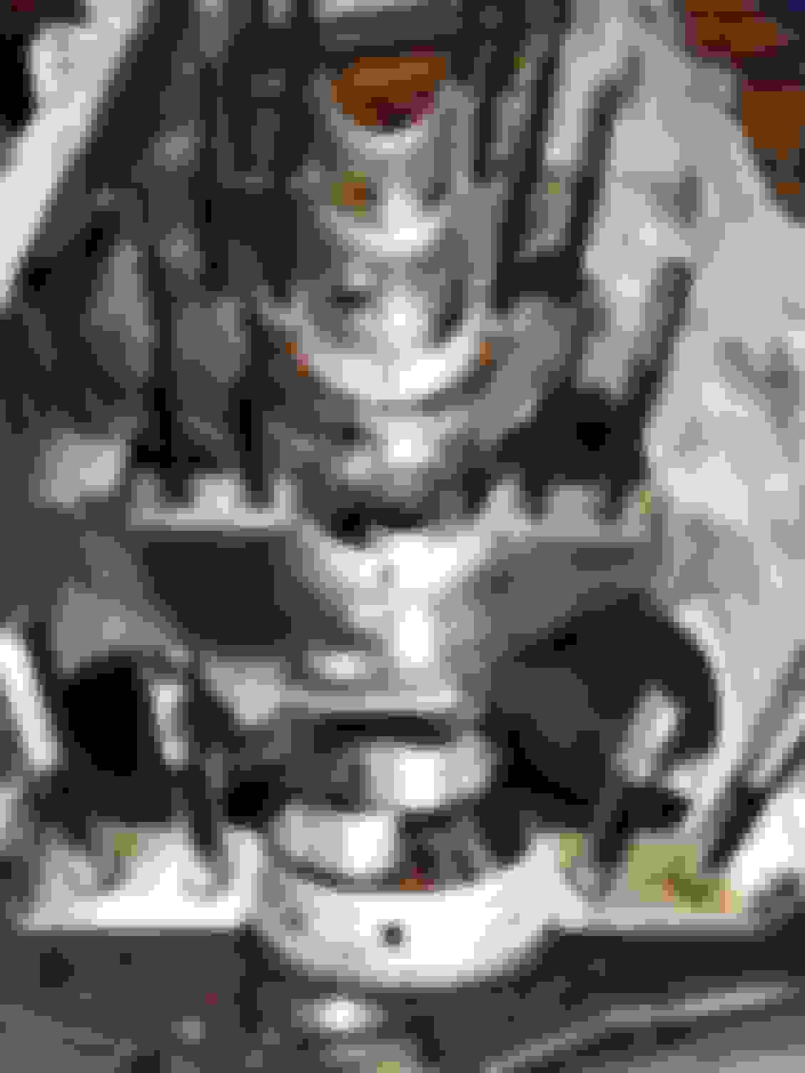
Not sure if the front surface shows signs of wear at all, ive seen new bearings look similar to that surface; but you may be on the right track judging by the transmission facing surface:
I see a LOT of thrust clearances set up much too tight on ls engines, which is why I asked in my earlier post where your thrust was set up at. I’ve yet to assemble an ls engine, where I didn’t have to do considerable work to the thrust, to achieve an acceptable number. Your thrust looks bad, with lots of wear from the crank, not a setup table. This go around, make sure you ask whomever assembles your shortblock to give you set up clearances on paper. If they refuse, go somewhere else. I’m not saying your thrust was the complete reason for this particular failure, but I’d venture to say that is where the debris started from. Debris in an engine ALWAYS causes more debris. It’s never the other way around.
Looks like those cam bearings had a lot of trash through them too.
I suspect the engine was not cleaned properly.as mentioned previously. The abrasive can and will get stuck in the oil galleries on the block as well as the crank.
I also suspect the end play was not set up properly. If you look at the wear on the bearing journal as well as the Thrust face. It appears to be worn more to one side. There might also be an issue with the line bore of the block Enough that it wouldnt hurt for a machinist to kiss it with a line hone
I would be curious to hear Lance's thoughts on this.
Hi Hero, I would like to see a picture of the center Main on the crankcase, the rear/front of the bearing.
Dirt problems work the dirt from the rear to front AND Oil Pressure problems work hot oil damage from front to back.
The first picture STATES a LARGE AMOUNT of Moly Paste is present in the oil and causes the filter to plug, then the safety valve opens.
I DO NOT USE Moly Assembly Lube, sure I use the ARP thread paste. (very little)
I NEVER use the early GEN-III crankcase as it cracks in the air hole area, the hole between the Cam Tunnel AND Main Tunnel. (as pictured)
I fit ARP Main Studs most often with a Steel Cap upgrade, thus little "tech" though I have done a align hone "kiss" by hand turning the bar.
Well quick update for you guys, stopped by the machine shop this morning with my oil filter and main caps to see what they thought. I did not offer any of my speculation or findings, and they also blamed the thrust. However they of course deny that it was their fault, and are pointing the finger at the drive-line. They assumed it was a 4-speed car, and were surprised to hear it was a T56... however that did not stop them from pointing the finger. I will be reporting back to them tomorrow with my thrust measurements as well as my receipt for the correct GM pilot bearing I used.
Originally Posted by Che70velle
I see a LOT of thrust clearances set up much too tight on ls engines, which is why I asked in my earlier post where your thrust was set up at. I�ve yet to assemble an ls engine, where I didn�t have to do considerable work to the thrust, to achieve an acceptable number. Your thrust looks bad, with lots of wear from the crank, not a setup table. This go around, make sure you ask whomever assembles your shortblock to give you set up clearances on paper. If they refuse, go somewhere else. I�m not saying your thrust was the complete reason for this particular failure, but I�d venture to say that is where the debris started from. Debris in an engine ALWAYS causes more debris. It�s never the other way around.
Thanks for the input! I will be checking thrust myself tonight with the existing bearings to see what it comes out to, even with the wear.
Originally Posted by 1FastBrick
Looks like those cam bearings had a lot of trash through them too.
I suspect the engine was not cleaned properly.as mentioned previously. The abrasive can and will get stuck in the oil galleries on the block as well as the crank.
I also suspect the end play was not set up properly. If you look at the wear on the bearing journal as well as the Thrust face. It appears to be worn more to one side. There might also be an issue with the line bore of the block Enough that it wouldnt hurt for a machinist to kiss it with a line hone
I would be curious to hear Lance's thoughts on this.
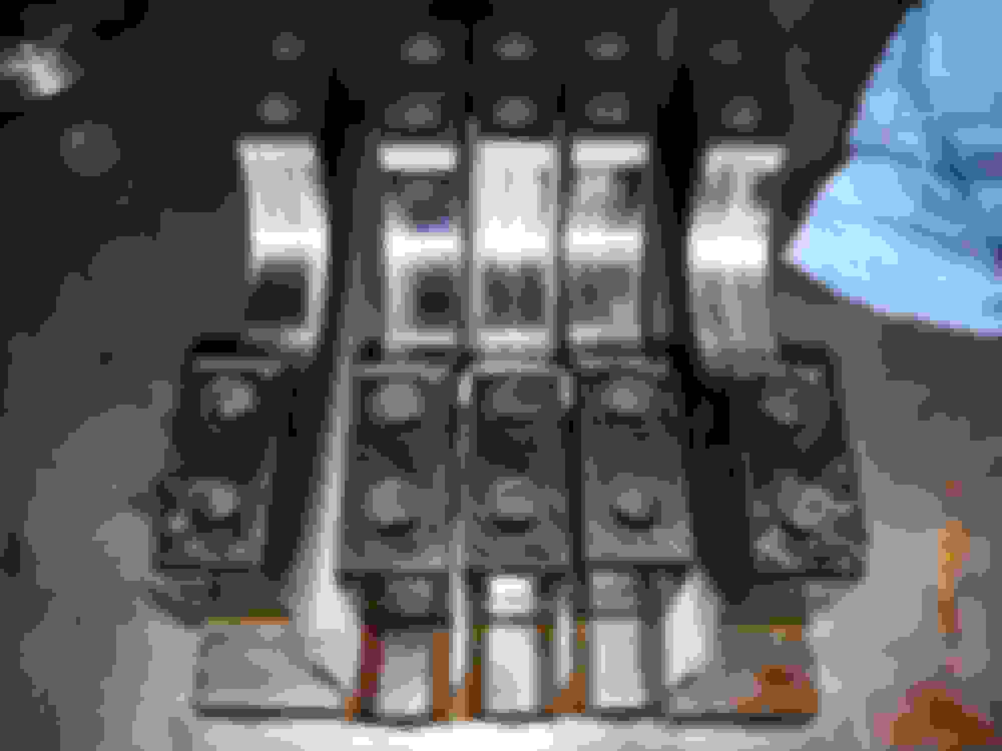
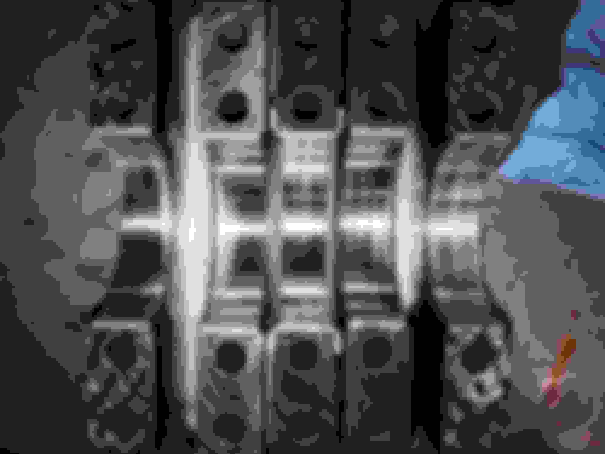
Thanks for the input. As I mentioned above , I will be checking a few more things tonight and report back. See the below photo of all the main caps in order and let me know if you still think this could be a line bore issue. I do not see a distinct enough pattern to say.
Originally Posted by Pantera EFI
Hi Hero, I would like to see a picture of the center Main on the crankcase, the rear/front of the bearing.
Dirt problems work the dirt from the rear to front AND Oil Pressure problems work hot oil damage from front to back.
The first picture STATES a LARGE AMOUNT of Moly Paste is present in the oil and causes the filter to plug, then the safety valve opens.
I DO NOT USE Moly Assembly Lube, sure I use the ARP thread paste. (very little)
I NEVER use the early GEN-III crankcase as it cracks in the air hole area, the hole between the Cam Tunnel AND Main Tunnel. (as pictured)
I fit ARP Main Studs most often with a Steel Cap upgrade, thus little "tech" though I have done a align hone "kiss" by hand turning the bar.
Did YOU set the TO Bearing "free play"
Lance
WOW, this made a LOT of sense. I could not get past the fact that if this were caused by a thrust bearing failure, how the filter could not catch that. But the excessive moly triggering the filter bypass answers that question! I will have to ask the machine shop if they use the old red assy lube or moly as well. I did not set TO bearing freeplay. I am using a Monster stage 2 with 18 lb flywheel. No shims on the TO (OE GM f-body replacement).
Last edited by rndmheroxx; 05-08-2018 at 11:41 AM.
Hi Hero, again the best pictures, good for ALL LS-1 members.
The Thrust wear IS on the Flywheel side AND even top/bottom, this states the "love" tap was done for cap centering.
I would INSPECT the Main Saddles for small cracks after removing the bearings.
Lance
Again, I appreciate the continued insight! Of course, the one thing you mentioned, I completely forgot to check.
However, I did manage to procure a dial indicator to check thrust. The thrust was first "set", then 3 mains were torqued to ~20 lb-ft, and the crank was smacked in both directions with a dead blow.
I checked it use the existing bearings; so keep that in mind. I will let you(all) make your own interpretations of my measurements. Also note that my technique was not 100%, the indicator post is threaded directly into the block, however it is pointing at a slightly downward angle to read off the reluctor wheel; so some basic trigonometry would say that theoretically this number is LARGER than the actual thrust.
*EDIT: pictures dont seem to be appearing. Stay tuned.
Last edited by rndmheroxx; 05-09-2018 at 09:11 AM.
Hi Hero, I read your method with possible error reported.
Sure torque to 20 .lbs, THEN loosen the center main, THEN a "love" tap, THEN re-tighten the center cap.
Hi Hero, I read your method with possible error reported.
Sure torque to 20 .lbs, THEN loosen the center main, THEN a "love" tap, THEN re-tighten the center cap.
Lance
Lance, sorry If i was unclear, that IS the method I use to obtain the above measurements.
Your mains look about like mine after losing the thrust.
My oil never looked bad at all, and I cut the filter at each oil change.
Mine is an L33 turbo making in excess of 1000 Crank HP.
Like you, I didn�t assemble my short block. So I don�t know what the thrust clearance was at assembly. My guess is .003� based on measuring new bearings. It ended up at .012�.
So question. What should we be setting this to at assembly?
There is a bearing mod mod that can be done to provide additional oil to the thrust. I�m going to look into that.
I have an auto trans, there were no thrust issues when the bottom end was stock
There's not much "setting" you can do... to change it, you have to weld up and/or grind down the crank. You could shave the bearings down if you had to, but I wouldn't do that if it could be avoided. In fact that might even be what happened to those, that exposed the copper.
.012" of thrust seems a bit much but by no means fatally problematic or anything. A bit too much isn't so bad, not near like not having enough, which could be fatal. Something in the .005 - .008" range would be better than .012", but that isn't the cause of all that metal in your oil.
I still can't figure out where all that metal dust came from. I'm just not seeing it. Even if your thrust bearings are damaged, which to me they really don't appear to be anyway, there's still only a gram or 2 of metal TOTAL missing from them, but your oil has like POUNDS of it.
I still can't figure out where all that metal dust came from. I'm just not seeing it. Even if your thrust bearings are damaged, which to me they really don't appear to be anyway, there's still only a gram or 2 of metal TOTAL missing from them, but your oil has like POUNDS of it.
My thoughts exactly, I've seen some nasty builds in my time where the block was machined and never cleaned properly that looked similar.
Ugh, there is alot going on here as others eluded to. Could be debris in the motor from assembly, but I wonder if something else was happening first. Maybe it's the pictures but your rod bearings look alot better than your mains. Your one picture suggests something to me though, and that is that some of the edges of your bearings aren't equally wiped. Which makes me wonder if your crankshaft line bore is outta whack or if your crank itself is outta whack. You studded the bottom end of the motor, that alone makes me wonder. If it were a contamination issue your rods and mains should all be equally wiped.
Thanks again all for following along and offering advice/opinions .
To catch you up to speed, after speaking with the machine shop, and discussing my concern about the <.003" thrust measurement ... I decied to drop by Thursday morning with the whole engine. They confirmed my measurement of ~ .0028" thrust with the bad bearing in place.
They still denied accountability, and claimed that I should have TOLD them i wanted more thrust. I did argue this, and request that they make it right, buy me new bearings &gaskets, polish the crank, and recheck all clearances. They met me halfway, and agreed to do any machine work required (and assembly if I wanted ) if I just bought the replacement bearings.
Kossuth, I am with you on that concern about the main bores. When i expressed that same concern to them, their response is "No, we checked that the first time, we know its good", and I had to insist that they PLEASE just recheck it. So they will recheck main bore, align hone if needed, put the crank in vblocks to check for main concentricity, repolish the crank, and put the rotating assembly back together.
SO, dropping of the new main bearings off tomorrow morning and we will go from there.... This time I will be going back over their work, most likely disassembling everything and ensuring its cleaned properly.
Your mains look about like mine after losing the thrust.
My oil never looked bad at all, and I cut the filter at each oil change.
Mine is an L33 turbo making in excess of 1000 Crank HP.
Like you, I didn�t assemble my short block. So I don�t know what the thrust clearance was at assembly. My guess is .003� based on measuring new bearings. It ended up at .012�.
So question. What should we be setting this to at assembly?
There is a bearing mod mod that can be done to provide additional oil to the thrust. I�m going to look into that.
I have an auto trans, there were no thrust issues when the bottom end was stock
Is yours still apart Ron? I was just wondering about that as I am going to throw together a L33 now. NOTHING like yours, but it did make me wonder how yours is?
That's nice they're working with you at some capacity. I wasn't so lucky with an old SBC 350 that was built by my local builder.
I made a post not long ago about cleaning your engine block yourself even after having it cleaned/hot tanked etc from the machine shop. Nobody's going to take the time needed to make sure everything is put together correctly as well
as you or any owner of the engine. With that said, since you're going to recheck their work and tear everything back apart, it might be worth just building the bottom end yourself after they check everything. That way you can go through
the bare block and clean, clean, clean everywhere inside and out on this engine to avoid any possible debris inside the oil passages (Which obviously there is on this engine at the moment).
Then reassemble, check thrust, main/rod clearances etc... That's what I'd do anyways. Good luck. I hope everything gets back on track without any further issues.
put a new #3 main bearing in same brand and check thrust
Im betting it will be closer to .001 which is way too tight.
Ive had very stiff clutches put excessive wear on thrust,to the point of
watching the balancer move as someone depressed the clutch.
not enough miles was put on this to do that.
Also how that block was stored for the 2 yrs before you got it may shed some light into this.
Mud dabbers will get in the tightest spots and make a nest. I have to cap off my rolls of rubber tubing
as Ive had them completely clog it up with a "nest".One small nest in just the right oil galley will play havoc.
Cleaning with rifle brushes should be SOP regardless of past history
during the initial teardown of block when you got it,did you read the bearings to see how straight the crank and align was?
There's not much "setting" you can do... to change it, you have to weld up and/or grind down the crank. You could shave the bearings down if you had to, but I wouldn't do that if it could be avoided. In fact that might even be what happened to those, that exposed the copper.
FWIW, sanding down the thrust is common practice in machine shops. I use a flat granite block and a fine grit sandpaper to sand the thrust surfaces on both sides of the bearing.
FWIW, sanding down the thrust is common practice in machine shops. I use a flat granite block and a fine grit sandpaper to sand the thrust surfaces on both sides of the bearing.
Agreed. I have a 2x2 pice of thick glass that I lay a new sheet of 800 grit on for each and every ls build I do. As I said earlier, I’ve not built one yet that I didn’t have to do significant work to the thrust bearing to achieve acceptable numbers. Don’t forget to oil your sand paper!
Last edited by Che70velle; 06-17-2018 at 01:40 PM.
Reason: add oil to sandpaper!

 05-07-2018, 02:03 PM