When you click on links to various merchants on this site and make a purchase, this can result in this site earning a commission. Affiliate programs and affiliations include, but are not limited to, the eBay Partner Network.
Doing my first LS assembly, have built many motors historically, all successful and ran for +100,000 miles thereafter. This one is a stock LS3 build, converted from L9H (L92 flex fuel), yet retaining truck intake. Have everything acquired, studied well here, and nothing seems difficult. Main and rod bearing clearances with new parts both spec @ 0.0015", top ring gap 0.014", 2nd 0.020", which are mid-spec for service. Pistons are new, 0.020" over.
Any tips/tricks/hints? Here are 2 I have found as example: (1) Some "align" the oil pump via 2 crank rotations before final torque fasten. The GM manual says nothing about alignment, just says bolt it on. (2) front cover seal centering done via tighten front cover bolts AFTER damper install. Seal is PTFE (Teflon). Seal lip edge should face in toward engine as naturally pushed that when installing damper? Rear seal lip edge also faces rearward, comes with guide to install over crank so seal lip edge stays facing out, check my thinking please.
Only piece non-stock is ARP head studs, and using LS9 gaskets in case it gets squeezed later (may not due to overbore though). Using LSA stainless intake and 2500HD LY6/L92 inconel exhaust valves, LS3 blue springs, 6k RPM limit (stock auto 4L60e trans, 6L80e later), 823 heads. I do have access to AllData factory service manual for tightening torques, sequences, and specs.
The main bearing bore was slightly ugly, machine shop ran a hone down it and now looks great. I still need to measure it's diameter to check bearing crush, possibly mill or flat plate sand the caps to reach spec (not sure yet). Shop said they were 0-1 thousandth larger and said should be OK. Not sure how I feel about that, zero main bearing shell sticking up on either tang when installed, seems completely flush with block. Rod bearing bores measure either perfect or half a thousandth large with slide caliper. Not sure I'm worried about it or not as well. You can clearly see the fractured parting line when the bolts are not tight, so there is a small amount of crush going on. Stock as-removed looked exactly the same. Bearing crush is kind of a difficult thing to quantify, all I have to go off is bearing bore ID, and probably should not be measuring with digital slide caliper but it is what it is, all I have beside is Harbor Freight spring loaded ID "snap" gauges (may work?). I already have King bearings in standard OD and 0.010" under ID for both to match the crank I exchanged for, and it seems like Clevite offers 2 thousandths over OD bearings, but I would need to stay stock or 1 thou over OD if I went with what I have, and I don't think they offer that. You could make it by swapping 1/2 a shell on each I guess. Would be better than spinning a bearing, especially with cold Michigan temps (was -18F start and drive to work just a few weeks ago).
I bought a set of the red AC Delco plug wires, but they seem too short/tight when fully installed. Anybody else experience this?
Main goal is for engine to be reliable as daily driver for 100,000-150,000 miles (22,0000/year), premium 93 oct fuel. May or may not get cam and headers later, going into 2009 Colorado 5.3L V8 4x4. Below pic is just part inventory, no assembly yet. Thanks for any input or suggestions.
Last edited by FormulaBoat; 03-01-2019 at 11:01 AM.
Main bore should be 2.558” to 2.559” and this needs to be right. If your machinist did the main hone and didn’t mill cut the caps first, chances are your mains are too big and bearing crush might not turn out right. Have your machinist measure this with a dial bore gauge.
I would re-confirm your main bearing clearance after this is sorted out.
Main bore should be 2.558� to 2.559� and this needs to be right. If your machinist did the main hone and didn�t mill cut the caps first, chances are your mains are too big and bearing crush might not turn out right. Have your machinist measure this with a dial bore gauge.
I would re-confirm your main bearing clearance after this is sorted out.
I believe you're thinking of the journal diameter. The housing bore is 2.7509-2.7515". You're right about cutting the caps though. The stock blocks are usually on the high end and could easily be out of tolerance if they're honed without cutting the caps.
I believe you're thinking of the journal diameter. The housing bore is 2.7509-2.7515". You're right about cutting the caps though. The stock blocks are usually on the high end and could easily be out of tolerance if they're honed without cutting the caps.
Thanks for the catch Kent. You are correct, I posted crank journal diameter instead of housing bore ID.
Doing my first LS assembly, have built many motors historically, all successful and ran for +100,000 miles thereafter. This one is a stock LS3 build, converted from L9H (L92 flex fuel), yet retaining truck intake. Have everything acquired, studied well here, and nothing seems difficult. Main and rod bearing clearances with new parts both spec @ 0.0015", top ring gap 0.014", 2nd 0.020", which are mid-spec for service. Pistons are new, 0.020" over.
Any tips/tricks/hints? Here are 2 I have found as example: (1) Some "align" the oil pump via 2 crank rotations before final torque fasten. The GM manual says nothing about alignment, just says bolt it on. (2) front cover seal centering done via tighten front cover bolts AFTER damper install. Seal is PTFE (Teflon). Seal lip edge should face in toward engine as naturally pushed that when installing damper? Rear seal lip edge also faces rearward, comes with guide to install over crank so seal lip edge stays facing out, check my thinking please.
Only piece non-stock is ARP head studs, and using LS9 gaskets in case it gets squeezed later (may not due to overbore though). Using LSA stainless intake and 2500HD LY6/L92 inconel exhaust valves, LS3 blue springs, 6k RPM limit (stock auto 4L60e trans, 6L80e later), 823 heads. I do have access to AllData factory service manual for tightening torques, sequences, and specs.
The main bearing bore was slightly ugly, machine shop ran a hone down it and now looks great. I still need to measure it's diameter to check bearing crush, possibly mill or flat plate sand the caps to reach spec (not sure yet). Shop said they were 0-1 thousandth larger and said should be OK. Not sure how I feel about that, zero main bearing shell sticking up on either tang when installed, seems completely flush with block. Rod bearing bores measure either perfect or half a thousandth large with slide caliper. Not sure I'm worried about it or not as well. You can clearly see the fractured parting line when the bolts are not tight, so there is a small amount of crush going on. Stock as-removed looked exactly the same. Bearing crush is kind of a difficult thing to quantify, all I have to go off is bearing bore ID, and probably should not be measuring with digital slide caliper but it is what it is, all I have beside is Harbor Freight spring loaded ID "snap" gauges (may work?). I already have King bearings in standard OD and 0.010" under ID for both to match the crank I exchanged for, and it seems like Clevite offers 2 thousandths over OD bearings, but I would need to stay stock or 1 thou over OD if I went with what I have, and I don't think they offer that. You could make it by swapping 1/2 a shell on each I guess. Would be better than spinning a bearing, especially with cold Michigan temps (was -18F start and drive to work just a few weeks ago).
I bought a set of the red AC Delco plug wires, but they seem too short/tight when fully installed. Anybody else experience this?
Main goal is for engine to be reliable as daily driver for 100,000-150,000 miles (22,0000/year), premium 93 oct fuel. May or may not get cam and headers later, going into 2009 Colorado 5.3L V8 4x4. Below pic is just part inventory, no assembly yet. Thanks for any input or suggestions.
Since the main cap and bearing info has been gone over...
The original way we assembled the engines at the engine assembly plant was to have then engine oil pump set against the cylinder block with the 4 bolts hand tight, so that the entire oil pump assembly could move with rotation of the crankshaft.
We did indeed center the oil pump as you mentioned by rotating the crankshaft 1080.00 degrees at a time once or twice then a pneumatic driver spun and torqued the 4 oil pump to cylinder block bolts all at once.
This method will suffice for a stock assembly or rebuild. Nothing else is usually needed. However there are better/ more precise methods for those of you that find the smallest of details matter (such as myself).
I prefer to start off in the same manor, however while the 4 bolts are hand tight... I remove the oil pump cover from the body to view the oil pump gears. I also remove the pressure relief valvetrain completely.
The 4 bolts and the treads in the cylinder block should be cleaned with brake parts cleaner and completely dry.
Next, I usually obtain three 0.0020" feeler gauges (that is two thousandths, please do not be confused by the way I express two thousandths in numerical form). Also lubricate the gear set with WD40.
I place the 3 feeler gauges between the body of the oil pump housing and the outer most gerotor. Spread out the 3 feeler gauges to something along the lines of 12 o'clock, 4 o'clock, and 8 o'clock.
Once the pump is centered, tighten and torque the 4 bolts between the oil pump and cylinder block to 18.00 Ft/Lbs in a criss-cross pattern. DO NOT forget to remove the 3 feeler gauges and make sure the gear set rotates with out interruption.
Spray the inside of the oil pump cover and the gear set with some valve spring spray oil (IE: Comp Cams product... extremely sticky stuff/ does not run down).
Install and torque the 7 oil pump cover bolts to the housing to 106.00 In/Lbs (INCH POUNDS NOT FOOT POUNDS) in a criss-cross pattern with red thread locking compound.
Rotate the engine assembly upside-down if not previously in that position. Obtain liquid assembly lubricant (IE: Royal Purple's product)
Add lube into the hole for the pressure relief valvetrain and reinstall the pressure relief valvetrain (add a stiffer spring and/ or a shim if desired for elevated oil pressure).
Torque the threaded plug for the pressure relief valvetrain to 106.00 In/Lbs with red thread locking compound.
Add liquid assembly lubricant (IE: Royal Purple's product) into the hole for the pick-up tube, lubricate and add the O-ring that is sized for the needed pick-up tube.
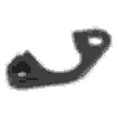
It is also recommended on every rebuild to add a billet collar/ brace for the pick-up tube to better attach it to the oil pump housing (see photo) via the means of a second bolt into the available unused threaded hole in the oil pump housing.
There are a hundred different companies making this part now...
Lubricate the oil pump pick-up tube as it enters the oil pump housing and o-ring.
Torque both bolts using the collar/ brace with the pick-up tube to the oil pump housing to 106.00 In/Lbs with red thread locking compound.
I'll measure them with a bore gauge and go from there. If off, I do have a Bridgeport here at work, looks easy enough to give the mains a slight haircut, or even just flat plate sand them if they only need a kiss to reach spec range.
Any other input or things I am not considering? Just jamb it together and go, I think. Thanks.
As far as correctly positioning and centering the front and rear engine covers...
First obtain a 18.00" to 24.00" long, 0.1250" to 0.2500" wide machinist straight-edge.
Second, obtain a set of specifically made aftermarket tools for this task (such as from Sac City Corvette's "Align-It Tools").
Several companies manufacture these tool sets now and I even prefer them over the GM manufactured tools for this job.
See Photo:
With the cylinder block upside-down (ideally) loosely install each cover with the bolts hand tight.
Align the the machinist straight-edge to the oil pan rails, as well as the bottom face of the cover being installed.
Install the corresponding "Align-It" tool into the seal bore of the cover without the seal installed.
Once the machinist straight-edge and "Align-It" tool has done their job centering the cover, tighten and torque the appropriate bolts to 18.00 Ft/Lbs clean and dry.
Now use the "Align-It" tool as a seal driver to install the corresponding seal into the cover.
A PTFE type (IE: "Teflon" which is a brand name like Xerox or Kleenex) seal should be used with these engine covers.
They are installed clean and dry (NO LUBRICANT ETC).
These instructions apply to both the front engine cover and the rear engine cover.
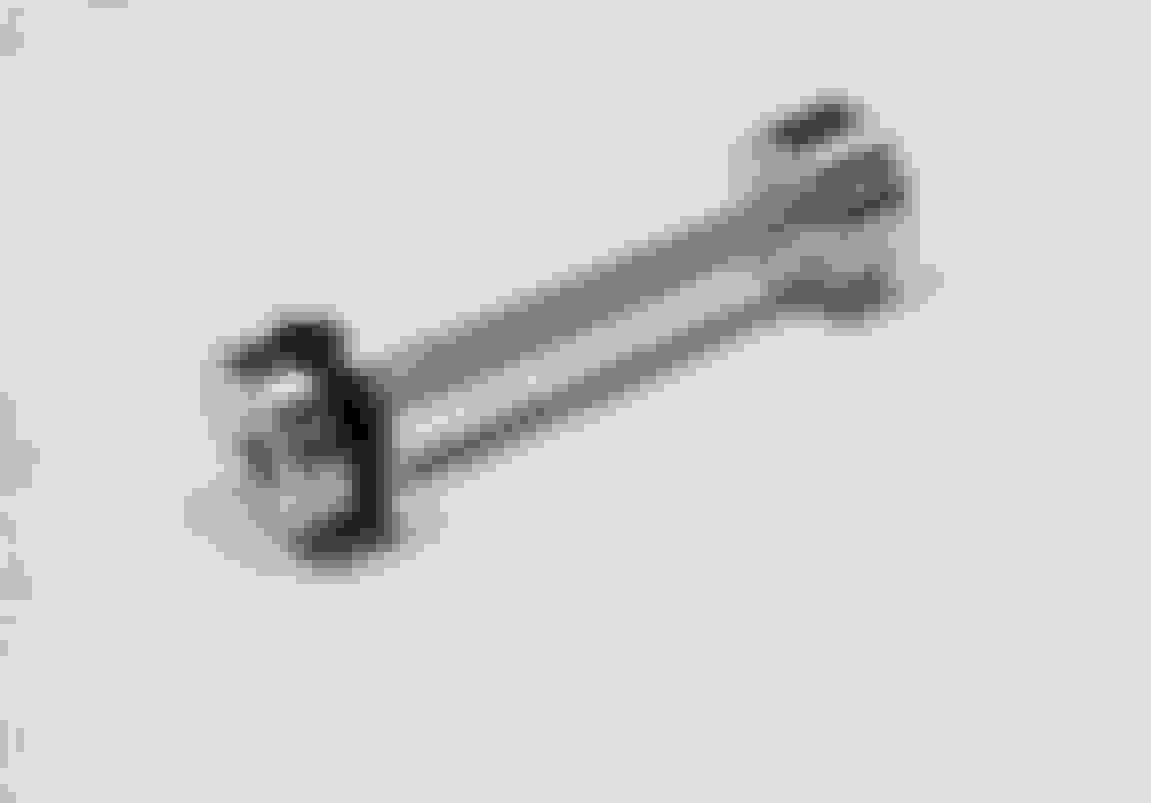
Also if looking to Sac City Corvette's for these tools or any other reason... I rather like their front engine oil plug and rear engine "Bar-Bell" plug designs.
Take a look:
Thanks all. You took a lot of time to write all that out. I appreciate it. Knew most of it, but by hearing it again, it stresses the importance of it. I did buy the oil pickup tube brace, need to get longer 6mm bolts though. It came with bolts too large of diameter. They won�t even fit through the brace itself.
I was trying to avoid the seal alignment tools, but..... I bought a new GM front cover that came complete with cam sensor, seals, and bolts. The crank seal is already installed, and I don�t really want to knock it out or buy the $1000 dealership bar type alignment tool. TBD on that one.
No need to remove the front cover crankshaft seal.
The smallest alignment tool in the set of three is for performing cover alignment with the seal already installed. (does not apply to the rear cover... No such tool included).
Thanks all. You took a lot of time to write all that out. I appreciate it. Knew most of it, but by hearing it again, it stresses the importance of it. I did buy the oil pickup tube brace, need to get longer 6mm bolts though. It came with bolts too large of diameter. They won�t even fit through the brace itself.
I was trying to avoid the seal alignment tools, but..... I bought a new GM front cover that came complete with cam sensor, seals, and bolts. The crank seal is already installed, and I don�t really want to knock it out or buy the $1000 dealership bar type alignment tool. TBD on that one.
Put the front cover on and leave the bolts loose. Install the damper and that will center the cover properly before you tighten the bolts. No need for the tools. Also it�s important to make sure the cover is level with pan rails at bottom also. That will lessen the chance of a potential leak. Rear cover is same way, but crank flange centers it for you instead of damper. I�ve assembled a dozen engines this way with no leaks.
Put the front cover on and leave the bolts loose. Install the damper and that will center the cover properly before you tighten the bolts. No need for the tools. Also it�s important to make sure the cover is level with pan rails at bottom also. That will lessen the chance of a potential leak. Rear cover is same way, but crank flange centers it for you instead of damper. I�ve assembled a dozen engines this way with no leaks.
Being that most people here will perform these tasks without any specialized tools, I must say that 90.00 percent of the time people here are doing just what you stated and work out perfectly 99.00 percent of the time.
So on that note: If I did not have the resources that I do, I would get a used harmonic balancer from the junk yard or EBAY... Cut off the actual balancer, leaving only the shaft. Hone out the ID of the shaft until achieving a slide on/ off fit to the crankshaft snout.
Cheap alignment tool done with a hack saw and an electric drill/ screw gun with a brake wheel cylinder hone inserted.
I just picked up 0.002" OD oversize rod bearings, and going to mix them with the standard OD size, to achieve 0.001" OD over on the rod bearings. This will essentially take the rod big end bore ID from the high end of the service spec, down to the low end. I will have a second set of the same bearings available to do the same thing if anybody needs. Priced $10 less than cost to do so on your own and free shipping, ad in the marketplace. For 10 under crank journal.
I'm probably being too intense on things like this over 1 thou of crush, but the drive to work just a few weeks ago was -18F, and I'd hate to spin a bearing on cold start up with cold/thick oil, when I have a chance to prevent it now for only $22 added cost of a second set of bearings. Temps are not normally like that here, but still have to protect for when it is and does happen. King bearings had a study published about bearing crush vs retention, and because it is an exponential relationship, it made me really want to consider my operating conditions and then lean toward the low end of the service limit for rod big end bore ID. I've used King bearing in my past few builds, and they have held up excellent. Most bearings probably do as well, but just FYI.

 03-01-2019, 09:21 AM