Gne 4 LQ4 rod/piston orientation dimples
#1
So I've seen so many mixed opinions on which way my gen 4 lq4 rods go. The rods have dimples on one side. I've heard the dimples on the rods face backwards and the dots on the pistons face forwards. I've also heard it doesn't matter. Can someone please help me put this to bed?
#2
ModSquad
iTrader: (6)
Casper, it’s been done both ways without issue. The dimples aren’t there for orientation. Always look at the rods big end cheek chamfer for proper placement with most any rod except maybe certain piston guided setups. If the crankshaft has a radius at the rod journal edge, which Oem LS cranks do not have, Aftermarket cranks do have, then you would make sure to orient your connecting rods chamfer to the outside of the journal. So since the LS cranks don’t have the radius, and the rods don’t have the chamfer, it really doesn’t matter which way they face. Personally I turn all mine toward the front, but it’s just a matter of preference.
The following users liked this post:
Homer_Simpson (05-02-2023)
#3
Casper, itís been done both ways without issue. The dimples arenít there for orientation. Always look at the rods big end cheek chamfer for proper placement with most any rod except maybe certain piston guided setups. If the crankshaft has a radius at the rod journal edge, which Oem LS cranks do not have, Aftermarket cranks do have, then you would make sure to orient your connecting rods chamfer to the outside of the journal. So since the LS cranks donít have the radius, and the rods donít have the chamfer, it really doesnít matter which way they face. Personally I turn all mine toward the front, but itís just a matter of preference.
#4
TECH Junkie
The orientation of the bulge on the shaft of the connecting rod is not important, because the location of that bulge varies between different model connecting rods.
Just as " Che70velle" stated... LOOK ONLY at the big end of the connecting rod!
The flatter side of the big end of the connecting rod always faces another connecting rod flat side (IE: two connecting rods facing one another, mirrored).
The chamfered side of the big end of the connecting rod always faces towards the main journal and bearing.
If the piston has a direction mark (or dot, or arrow) ,the piston will "Almost ALWAYS" have that directional mark intended to be directed towards the front of the engine.
There are rare situations where this piston rule does not apply, however unless working with custom parts... This exception to the rule should not be experienced.
The following users liked this post:
Homer_Simpson (05-02-2023)
#5
TECH Junkie
I forgot to state that the chamfered side of the connecting rod is only meant to meet the mirrored angle chamfer on the crankshaft. This is know as the crankshaft journal fillet.
While most of the LSx engines have crankshafts with minimal crankshaft journal fillets (And most people think that they are not even there) Do not stray from what I tell you here.
When I was a powertrain engineer with GM... This topic of a small or un-pronounced crankshaft journal fillet was discussed in-house as a joke that will plague the high performance rebuilder for an eternity...
The factory procedure for assembly and for repair all follow the normal rule for structural integrity.
The DIYer often does not know to follow the standard rule and can get away with the incorrect orientation to some extent do to loose fitment/ tolerances.
NEVER put a flat side towards a chamfered side component!
One there will be metal wearing away and getting circulated through the engine oiling system in most engines (excluding most LSx stock engines)
Two this combination would create a structural weakness.
DO NOT, DO NOT attempt this.
Last edited by vorteciroc; 03-02-2019 at 01:36 PM.
The following users liked this post:
Homer_Simpson (05-02-2023)
#7
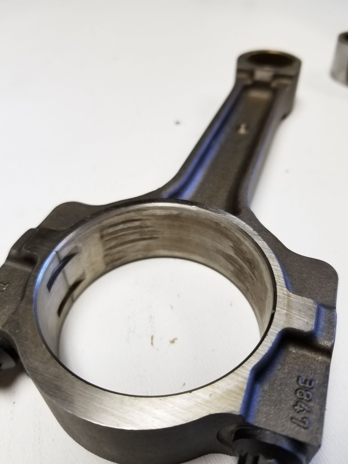
Heres the smooth machined chamfer side
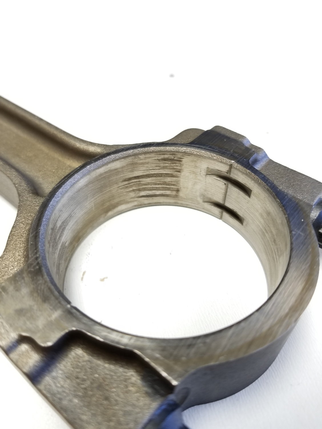
Heres the rough chanfer as cast side
I didn't realize both sides are chamfered. Does this mean the smooth machined chamfer both face outwards towards the crank weight?
Trending Topics
#8
TECH Junkie
On the stock connecting rods... the chamfer is very small as is the crank journal fillet.
The first photo would have the connecting rod face the crankshaft journal fillet and the second photo would would have the connecting rod face another connecting rod.
What you see on these connecting rods essentially would be a double sided flat faced connecting rod compared to traditional NON-LSx based factory connecting rods.
Neither side really has a true chamfer that would ride against a traditional crankshaft journal fillet.
Both sides have a teeny tiny chamfer that would make-up a traditional flat side.
On these connecting rods (As you noticed), one side has a machined smooth chamfer... most people are oblivious to this, it seems...
So usually with these particular connecting rods, I state that:
The visual difference on the connecting rods pictured, would be the difference in the flat machined material at the fracture point of the connecting rod.
The side with the wider flat machined surface, faces another connecting of the mirrored surface.
Last edited by vorteciroc; 03-02-2019 at 06:48 PM.
The following 2 users liked this post by vorteciroc:
dc5423 (09-15-2022), Homer_Simpson (05-02-2023)
#9
Moderator
iTrader: (20)
I forgot to state that the chamfered side of the connecting rod is only meant to meet the mirrored angle chamfer on the crankshaft. This is know as the crankshaft journal fillet.
While most of the LSx engines have crankshafts with minimal crankshaft journal fillets (And most people think that they are not even there) Do not stray from what I tell you here.
When I was a powertrain engineer with GM... This topic of a small or un-pronounced crankshaft journal fillet was discussed in-house as a joke that will plague the high performance rebuilder for an eternity...
The factory procedure for assembly and for repair all follow the normal rule for structural integrity.
The DIYer often does not know to follow the standard rule and can get away with the incorrect orientation to some extent do to loose fitment/ tolerances.
NEVER put a flat side towards a chamfered side component!
One there will be metal wearing away and getting circulated through the engine oiling system in most engines (excluding most LSx stock engines)
Two this combination would create a structural weakness.
DO NOT, DO NOT attempt this.
While most of the LSx engines have crankshafts with minimal crankshaft journal fillets (And most people think that they are not even there) Do not stray from what I tell you here.
When I was a powertrain engineer with GM... This topic of a small or un-pronounced crankshaft journal fillet was discussed in-house as a joke that will plague the high performance rebuilder for an eternity...
The factory procedure for assembly and for repair all follow the normal rule for structural integrity.
The DIYer often does not know to follow the standard rule and can get away with the incorrect orientation to some extent do to loose fitment/ tolerances.
NEVER put a flat side towards a chamfered side component!
One there will be metal wearing away and getting circulated through the engine oiling system in most engines (excluding most LSx stock engines)
Two this combination would create a structural weakness.
DO NOT, DO NOT attempt this.
#10
TECH Junkie
I agree, On LSx based engines there will be not metal debris produced.
I only state one should follow the normal orientation due to habit formation.
Metal debris and structural integrity concerns are inevitable outside of these factory LSx based parts...
I only state one should follow the normal orientation due to habit formation.
Metal debris and structural integrity concerns are inevitable outside of these factory LSx based parts...
#12
Look. I'm a single mom with a special needs kid. I am rebuilding my 2003 Vortec 6.0 LQ9 engine my my block is the earlier model with the smaller camshaft bores from 2002-2003. They changed the sizes in 2003-2007. I only know this because while trying to knock in some " standard size " cam bearings I was catching hell and I knew something was amiss because I had no problem getting my bearings out. I did research and just as I suspected there are two sizes for 2003 because of the change and I had the first ones. Ordered the smaller bearings and the dang things went in like butter. Anyway moving on now I'm on the verge of torquing my main bolts but before I do and before I torque anything else I need to make sure I install my connecting rods correctly. I have them installed but not torqued. The way I installed them is by the dot on the rods. My pistons are all facing the correct direction. ( dot on piston facing front of the engine (( I have flat tops )), ). Any way I installed my rods with the dimples or dots facing opposite one another so one faces front and the other faces back. I would like to know the manufactures recommendations on how to install these rods. Because I want to do this right the first time. Been working on this for weeks and I've had multiple delays and maybe that's a good thing especially if I have installed my rods wrong. I'm 49 years old my eyes aren't as good as they used to be so if someone can give me dummy answers or dummy visuals I'd really appreciate it. Thanks.
#13
Look. I'm a single mom with a special needs kid. I am rebuilding my 2003 Vortec 6.0 LQ9 engine my my block is the earlier model with the smaller camshaft bores from 2002-2003. They changed the sizes in 2003-2007. I only know this because while trying to knock in some " standard size " cam bearings I was catching hell and I knew something was amiss because I had no problem getting my bearings out. I did research and just as I suspected there are two sizes for 2003 because of the change and I had the first ones. Ordered the smaller bearings and the dang things went in like butter. Anyway moving on now I'm on the verge of torquing my main bolts but before I do and before I torque anything else I need to make sure I install my connecting rods correctly. I have them installed but not torqued. The way I installed them is by the dot on the rods. My pistons are all facing the correct direction. ( dot on piston facing front of the engine (( I have flat tops )), ). Any way I installed my rods with the dimples or dots facing opposite one another so one faces front and the other faces back. I would like to know the manufactures recommendations on how to install these rods. Because I want to do this right the first time. Been working on this for weeks and I've had multiple delays and maybe that's a good thing especially if I have installed my rods wrong. I'm 49 years old my eyes aren't as good as they used to be so if someone can give me dummy answers or dummy visuals I'd really appreciate it. Thanks.
The following users liked this post:
Homer_Simpson (05-02-2023)
#14
TECH Senior Member
iTrader: (16)
Look. I'm a single mom with a special needs kid. I am rebuilding my 2003 Vortec 6.0 LQ9 engine my my block is the earlier model with the smaller camshaft bores from 2002-2003. They changed the sizes in 2003-2007. I only know this because while trying to knock in some " standard size " cam bearings I was catching hell and I knew something was amiss because I had no problem getting my bearings out. I did research and just as I suspected there are two sizes for 2003 because of the change and I had the first ones. Ordered the smaller bearings and the dang things went in like butter. Anyway moving on now I'm on the verge of torquing my main bolts but before I do and before I torque anything else I need to make sure I install my connecting rods correctly. I have them installed but not torqued. The way I installed them is by the dot on the rods. My pistons are all facing the correct direction. ( dot on piston facing front of the engine (( I have flat tops )), ). Any way I installed my rods with the dimples or dots facing opposite one another so one faces front and the other faces back. I would like to know the manufactures recommendations on how to install these rods. Because I want to do this right the first time. Been working on this for weeks and I've had multiple delays and maybe that's a good thing especially if I have installed my rods wrong. I'm 49 years old my eyes aren't as good as they used to be so if someone can give me dummy answers or dummy visuals I'd really appreciate it. Thanks.
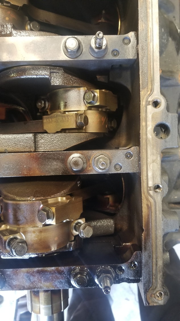
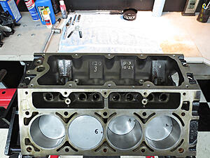
you can see all rods face same way on this motor I am dis-assembling. As KCS mentioned. They can face either way and still work.
#15
#16
TECH Enthusiast
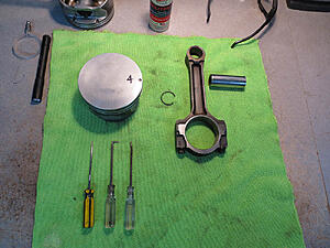
I carefully marked each piston to their corresponding bore during tear down so I could assemble the same pistons in the same bore. All rod dimples faced rearward and piston dots forward. I removed each piston wristpin to clean the varnish from their bores and reassembled dot to dimple in their original orientation. They will work either direction but my thinking was... no reason to change the engineers positioning.
#17
Thanks for your reply. I did go back earlier before torquing things down and reversed 4 rods so the dot was toward the rear of the engine. I got all new bearings, pistons, rings. I got everything torqued and installed other parts. I really appreciate your response as I want to keep everything and action as close to factory as possible. Not trying to be fancy with it but thorough.
The following users liked this post:
RedXray (09-01-2020)
#18
As you noticed one of the small chamfers is smooth and the other side has the chamfer rough cast.
On the stock connecting rods... the chamfer is very small as is the crank journal fillet.
The first photo would have the connecting rod face the crankshaft journal fillet and the second photo would would have the connecting rod face another connecting rod.
What you see on these connecting rods essentially would be a double sided flat faced connecting rod compared to traditional NON-LSx based factory connecting rods.
Neither side really has a true chamfer that would ride against a traditional crankshaft journal fillet.
Both sides have a teeny tiny chamfer that would make-up a traditional flat side.
On these connecting rods (As you noticed), one side has a machined smooth chamfer... most people are oblivious to this, it seems...
So usually with these particular connecting rods, I state that:
The visual difference on the connecting rods pictured, would be the difference in the flat machined material at the fracture point of the connecting rod.
The side with the wider flat machined surface, faces another connecting of the mirrored surface.
#19
TECH Enthusiast
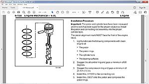
6.0 Manual attached
#20
This is correct Iíve done it many times and didnít see any metal and last for ever and still running


