
Follow along with an engine build @ Weber Racing Engines!!


 03-17-2008, 05:02 PM
#22
Teching In
Join Date: Oct 2007
Posts: 35
Likes: 0
Received 0 Likes
on
0 Posts
Leo - Looks good. I can't wait for my shortblock to be finished. I should post the before and after pics of the head repair you guys did; simply outstanding. I was so impressed with their machine work and customer service, I decided to order my shortblock from them.
For those considering a shortblock, definitely give these guys a call. They are extremely knowledgeable of the LS engines, always answer the phone and are straight shooters. Before they started my build, Leo sent me a quote detailing every step with an itemized cost for each step (down to the freight). No hidden charges or surprises. He even calls me with updates. I can't say enough good things about WRE. They have been great to deal with.
For those considering a shortblock, definitely give these guys a call. They are extremely knowledgeable of the LS engines, always answer the phone and are straight shooters. Before they started my build, Leo sent me a quote detailing every step with an itemized cost for each step (down to the freight). No hidden charges or surprises. He even calls me with updates. I can't say enough good things about WRE. They have been great to deal with.

Tom

 03-18-2008, 09:02 PM
#24
Banned
Thread Starter
iTrader: (4)
Join Date: Jan 2007
Location: North Ridgeville, Ohio
Posts: 539
Likes: 0
Received 0 Likes
on
0 Posts
Sorry for the delay everyone. We are having connectivity problems with the internet at the shop. We switched our voice over IP lines over the weekend and something was messed up. We should have this fixed by noon tomorrow. As soon as it is fixed I will be sure to update!
Thanks,
Leo
Thanks,
Leo
03-19-2008, 03:15 PM
#25
Banned
Thread Starter
iTrader: (4)
Join Date: Jan 2007
Location: North Ridgeville, Ohio
Posts: 539
Likes: 0
Received 0 Likes
on
0 Posts
Sorry for the delay everyone. We finally got our internet back and running better than ever. For the past 2 days the download rate was only 38 kbps. I guess we are getting spoiled with high speed. The uploads of the pictures was near impossible so I was not able to update the thread. But nonetheless here we are.
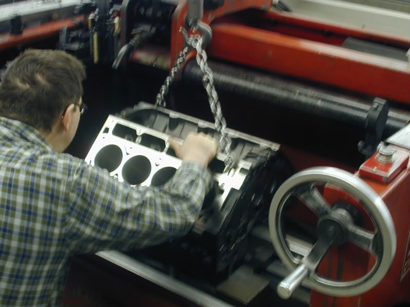
After the block comes out of the align hone it is taken over to the Sunnen Cylinder Hone. Usually the block would come to the cylinder hone first but we had a job setup over there that changed the flow of things a little bit.
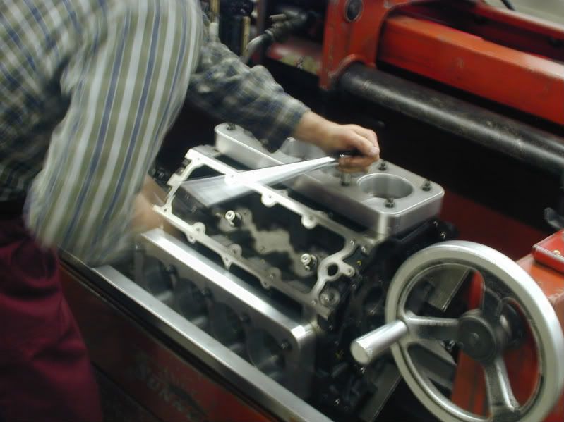
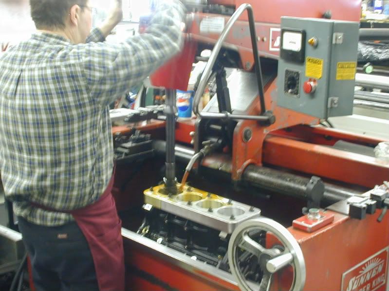
Here is a picture of Greg setting the block in the honing machine:
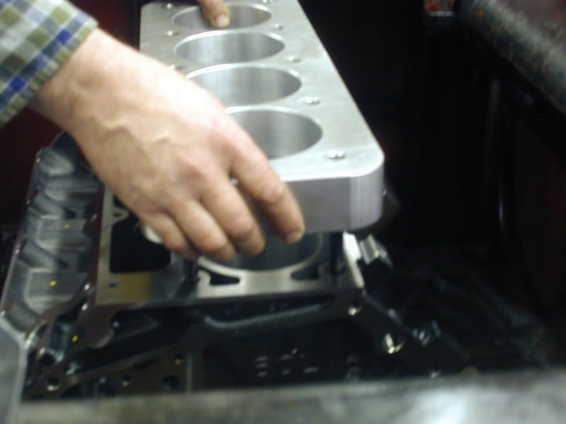
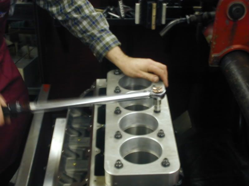
After the block is secure in the hone, head studs are installed and the torque plates are installed and torqued:
After the torque plates are installed the bores are checked for size. We use the same type of dial bore gauge that was used on the mains. I was pretty busy and running back and forth so I did not get a picture of Greg measuring the bores.
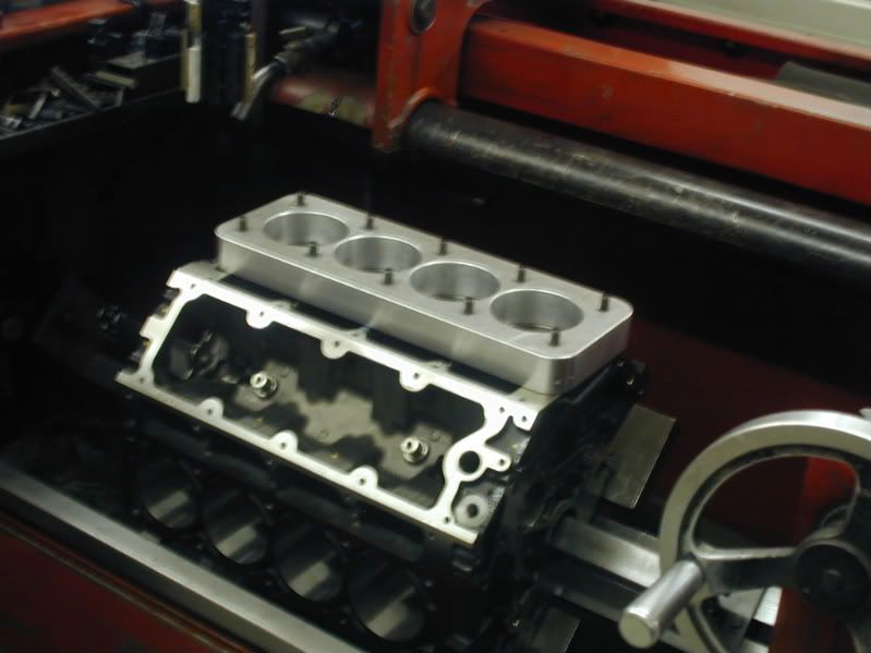
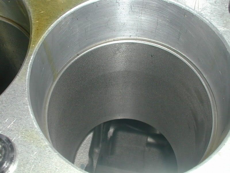
Here is the bore with the torque plate installed and the finish before we hone the bore:
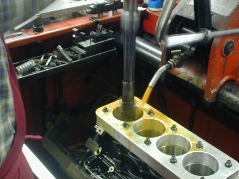
Here is Greg running the hone through the cylinder:
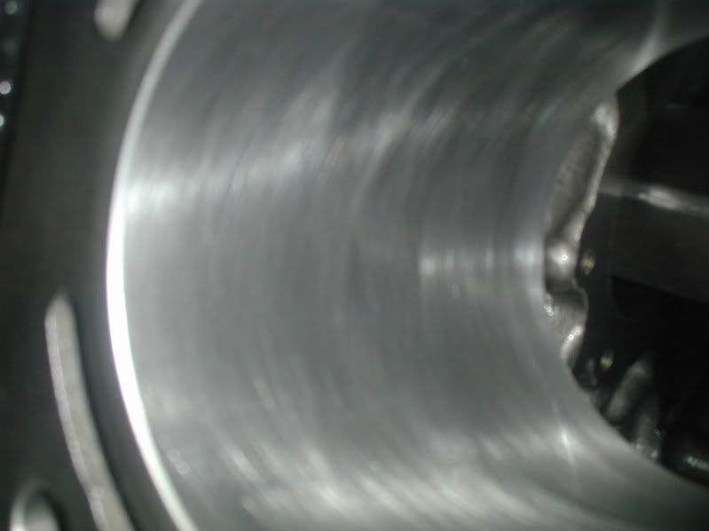
Now the ring finish and final product after the honing process is complete:
Now that the machining to the block is complete it will go over and get in line to be jet washed, dried and bagged to await assembly.
We are still waiting for the pistons and at the last minute changed to a solid roller camshaft. So we had to change the order in the heads. The guys at TEA are getting the heads done and we should have them when the custom pistons arrive in the first week of April.
Once the crankshaft, connecting rods and pistons are here I will be showing how the rotating assembly is balanced. After everything is balanced it is on to the assembly room where we end up with a completed engine. So STAY TUNED and please feel free to keep posting.pming/emailing your questions, comments and quote requests!
Thanks,
Leo
After the block comes out of the align hone it is taken over to the Sunnen Cylinder Hone. Usually the block would come to the cylinder hone first but we had a job setup over there that changed the flow of things a little bit.
Here is a picture of Greg setting the block in the honing machine:
After the block is secure in the hone, head studs are installed and the torque plates are installed and torqued:
After the torque plates are installed the bores are checked for size. We use the same type of dial bore gauge that was used on the mains. I was pretty busy and running back and forth so I did not get a picture of Greg measuring the bores.
Here is the bore with the torque plate installed and the finish before we hone the bore:
Here is Greg running the hone through the cylinder:
Now the ring finish and final product after the honing process is complete:
Now that the machining to the block is complete it will go over and get in line to be jet washed, dried and bagged to await assembly.
We are still waiting for the pistons and at the last minute changed to a solid roller camshaft. So we had to change the order in the heads. The guys at TEA are getting the heads done and we should have them when the custom pistons arrive in the first week of April.
Once the crankshaft, connecting rods and pistons are here I will be showing how the rotating assembly is balanced. After everything is balanced it is on to the assembly room where we end up with a completed engine. So STAY TUNED and please feel free to keep posting.pming/emailing your questions, comments and quote requests!
Thanks,
Leo
03-19-2008, 03:23 PM
#26
TECH Enthusiast

Join Date: Jan 2008
Posts: 625
Likes: 0
Received 0 Likes
on
0 Posts
Leo,
Why is the torque plate bolted to the head studs and torqued? Is it just to allow the studs a chance to get cranked on to make sure they are in solid?
Check your PM about the deposit on the LSX block you have in the shop and the build quote. Thanks.
Why is the torque plate bolted to the head studs and torqued? Is it just to allow the studs a chance to get cranked on to make sure they are in solid?
Check your PM about the deposit on the LSX block you have in the shop and the build quote. Thanks.
03-19-2008, 03:32 PM
#27
Banned
Thread Starter
iTrader: (4)
Join Date: Jan 2007
Location: North Ridgeville, Ohio
Posts: 539
Likes: 0
Received 0 Likes
on
0 Posts
-Leo
03-20-2008, 10:09 AM
#28
Banned
Thread Starter
iTrader: (4)
Join Date: Jan 2007
Location: North Ridgeville, Ohio
Posts: 539
Likes: 0
Received 0 Likes
on
0 Posts
Thanks,
Leo
03-20-2008, 11:13 AM
#29
I can shift faster than you.
iTrader: (21)

Join Date: Nov 2001
Location: Baton Rouge, LA
Posts: 5,133
Likes: 0
Received 0 Likes
on
0 Posts

Leo - cool pics!  Any reason why a head gasket was not used with the torque plates? I have found they do make a little bit of difference, especially at the top of the bore. Have you found otherwise?
Jason
Any reason why a head gasket was not used with the torque plates? I have found they do make a little bit of difference, especially at the top of the bore. Have you found otherwise?Jason
03-20-2008, 12:03 PM
#31
Teching In

Join Date: Aug 2007
Location: PA, OH, NC...
Posts: 8
Likes: 0
Received 0 Likes
on
0 Posts
Leo,
Any advantage to having the torque plates on there when the mains are align-bored/honed? I know on some blocks that aren't the strongest in the main webbing area, that they distort also when the heads are torqued down.
TIA,
K.
Any advantage to having the torque plates on there when the mains are align-bored/honed? I know on some blocks that aren't the strongest in the main webbing area, that they distort also when the heads are torqued down.
TIA,
K.
03-20-2008, 02:01 PM
#32
Banned
Thread Starter
iTrader: (4)
Join Date: Jan 2007
Location: North Ridgeville, Ohio
Posts: 539
Likes: 0
Received 0 Likes
on
0 Posts
We have found the difference to be very, very minimal. 99% of what we are trying to accomplish is done without a head gasket. We can only simulate so much distortion. We are honing the block at 70 deg. when it actually runs much higher than that. Really it can get crazy trying to simulate actual conditions.I'm sure there have been people that have gone to the point of pretty much bolting all accessories on a motor to try and simulate the distortion. Really where do you draw the line at how much expense are you going to incur trying to simulate actual conditions? Conditions that are IMPOSSIBLE to duplicate. At some point you have to draw a line at what is enough while maintaining a high level of quality.
03-20-2008, 02:03 PM
#33
Banned
Thread Starter
iTrader: (4)
Join Date: Jan 2007
Location: North Ridgeville, Ohio
Posts: 539
Likes: 0
Received 0 Likes
on
0 Posts
That is another issue of trying to simulate actual distortion. It really is not a problem and that is why we have not practiced that with the torque plates installed.
03-20-2008, 02:10 PM
#34
I can shift faster than you.
iTrader: (21)
Join Date: Nov 2001
Location: Baton Rouge, LA
Posts: 5,133
Likes: 0
Received 0 Likes
on
0 Posts
Agreed 100% Leo. It was just something I have always done as it does make a slight difference, but where do you draw the line?
I have found these motor don't distort the mains with or without the tq. plates attached as you stated.
Jason
I have found these motor don't distort the mains with or without the tq. plates attached as you stated.
Jason

 04-13-2008, 03:06 AM
#37
TECH Enthusiast
Join Date: Jan 2008
Posts: 625
Likes: 0
Received 0 Likes
on
0 Posts
Hope this doesn't sound stupid because theres probably something simple to an expert I don't know............BUT....
why not thread a cylinder and screw the sleeve in?
Or............after the sleeve is in tap screws into the cylinder walls to keep the sleeves from dropping? OF COURCSE, the screws would be at the very bottom where piston rings DO NOT TOUCH the screw heads that are ground down flat and smooth anyway.
Last edited by needadvice; 04-14-2008 at 09:18 AM.
04-13-2008, 01:57 PM
#38
On The Tree
iTrader: (14)

Join Date: Jan 2006
Location: St. Augustine, FL
Posts: 183
Likes: 0
Received 0 Likes
on
0 Posts
I think he has a few more pics to post, but you can blame me partially for the lack of updates. Little bit of a parts availability issue on some things and I don't feel like going with something else that is available. Balancing pics should be up soon.
04-15-2008, 09:09 AM
#39
Banned
Thread Starter
iTrader: (4)
Join Date: Jan 2007
Location: North Ridgeville, Ohio
Posts: 539
Likes: 0
Received 0 Likes
on
0 Posts
Ok everybody we are back to working on this engine. There was a good break in there due to some changes in the build. The day we started this thread we decided to go solid roller and the guys at TEA had to put together a custom solid roller setup set of 235cc Trickflow cylinder heads. Since we knew the heads would be a little bit and we were also waiting on the custom Wiseco pistons we took a break to get some other projects completed and out the door.
Now that the block is complete it went into the jet washer and was cleaned and bagged to wait in line for the assembly room. Unfortunatly I missed this part, but really there is nothing to see there. The block is in the jet washer and blown out with an air gun so it does not rust.
We have everything here for the rotating assembly to be balanced.
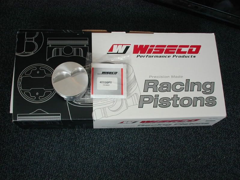
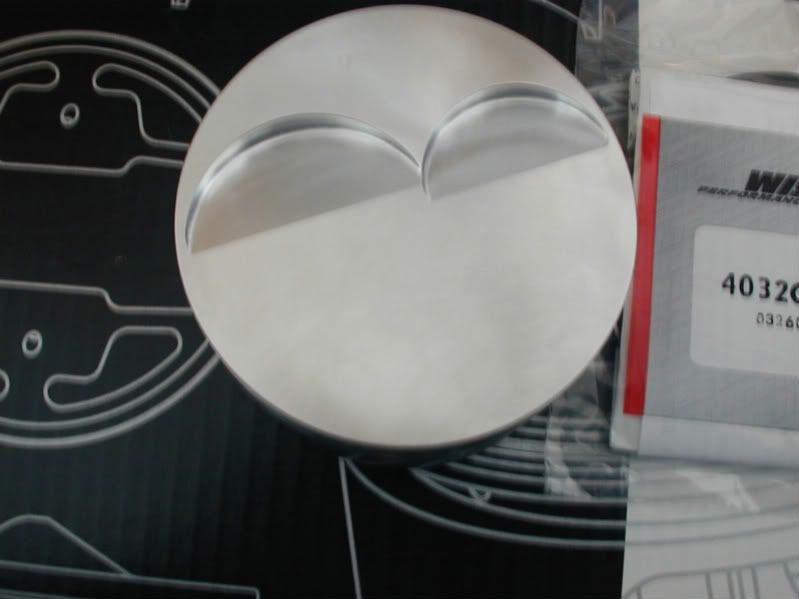
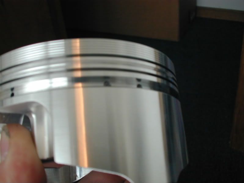
Here are the custom pistons from Wiseco:
The K1 Tech Connecting Rods (Which you will see pictures of later.)
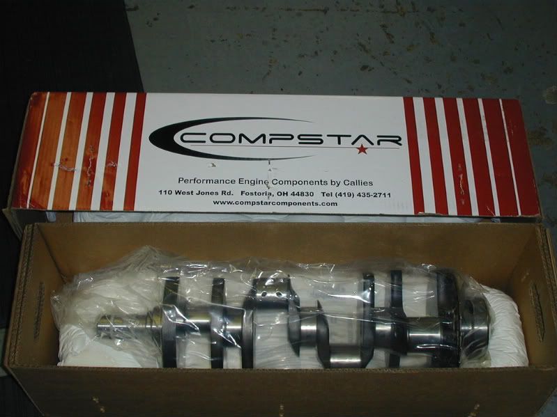
Callies Compstar 4.000 Stroke Crankshaft
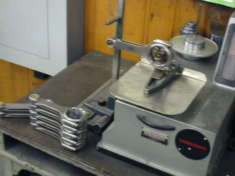
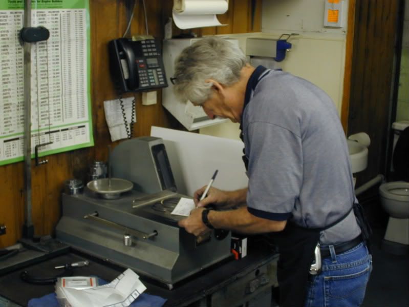
Everything is taken over the weigh station where Dave Weber will get rod, piston, ring and connecting rod weights to establish a bobweight so he can balance the crankshaft.
This is how the big end of the crank is weighed:
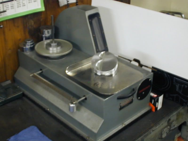
The pistons:
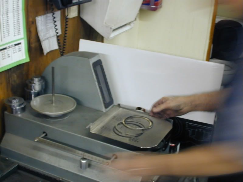
Piston Rings:
The rod bearings are also weighed and weights are recorded on a balance card that is kept on file:
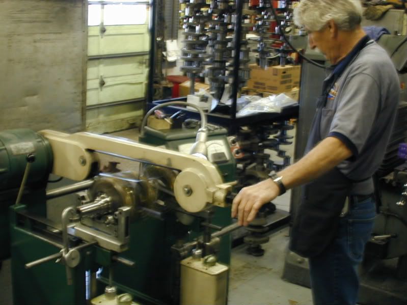
Next Dave sets up the crankshaft in the balancer with bobweights attached. When a crank is balanced it should sit in the balancer and not want to spin on its own at any point. There is alot more to balancing that I am not going to get into here. The bottom line is the crankshaft needs to be balanced so the engine will not vibrate and create harmonics and the engine to vibrate. This ensures a smooth running engine.
Here is a picture of Dave spinning the crankshaft on the balancer. While the crankshaft is spinning Dave is looking at the gauges to detect any loads that would detect the crank being out of balance.
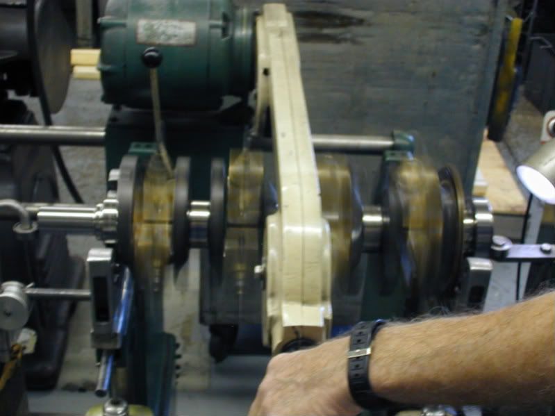
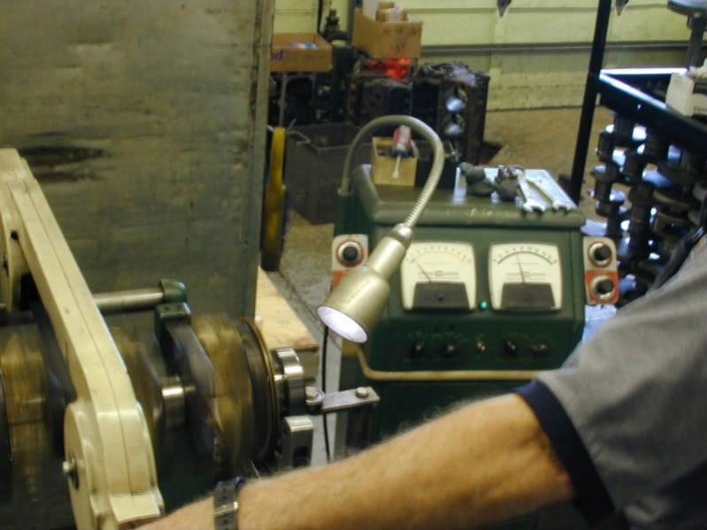
Even though these cranks are rough balanced, they still are not perfect. This one was off quite a bit. Dave than adds clay to the counter weights on the crankshaft. This clay is added and removed until a perfect balance is found.The clay is than weighed so we can see how much weight may need to be added or subtracted from the throws of the crank. This one needed some weight taken out.
When the weight is taken out of the crank by drilling into the counterweights of the crankshaft. Sorry I missed this part so do no have any pics of it. I will try to catch Dave working on another crank and get a pic for everyone to see.
Now that the block is complete it went into the jet washer and was cleaned and bagged to wait in line for the assembly room. Unfortunatly I missed this part, but really there is nothing to see there. The block is in the jet washer and blown out with an air gun so it does not rust.
We have everything here for the rotating assembly to be balanced.
Here are the custom pistons from Wiseco:
The K1 Tech Connecting Rods (Which you will see pictures of later.)
Callies Compstar 4.000 Stroke Crankshaft
Everything is taken over the weigh station where Dave Weber will get rod, piston, ring and connecting rod weights to establish a bobweight so he can balance the crankshaft.
This is how the big end of the crank is weighed:
The pistons:
Piston Rings:
The rod bearings are also weighed and weights are recorded on a balance card that is kept on file:
Next Dave sets up the crankshaft in the balancer with bobweights attached. When a crank is balanced it should sit in the balancer and not want to spin on its own at any point. There is alot more to balancing that I am not going to get into here. The bottom line is the crankshaft needs to be balanced so the engine will not vibrate and create harmonics and the engine to vibrate. This ensures a smooth running engine.
Here is a picture of Dave spinning the crankshaft on the balancer. While the crankshaft is spinning Dave is looking at the gauges to detect any loads that would detect the crank being out of balance.
Even though these cranks are rough balanced, they still are not perfect. This one was off quite a bit. Dave than adds clay to the counter weights on the crankshaft. This clay is added and removed until a perfect balance is found.The clay is than weighed so we can see how much weight may need to be added or subtracted from the throws of the crank. This one needed some weight taken out.
When the weight is taken out of the crank by drilling into the counterweights of the crankshaft. Sorry I missed this part so do no have any pics of it. I will try to catch Dave working on another crank and get a pic for everyone to see.
