Late Model Racecraft LT1 Cylinder Head CNC Program Underway!
 07-12-2013, 03:35 PM
#1
Closed ex-Sponsor Account
Thread Starter

Join Date: Jan 2012
Posts: 122
Likes: 0
Received 0 Likes
on
0 Posts
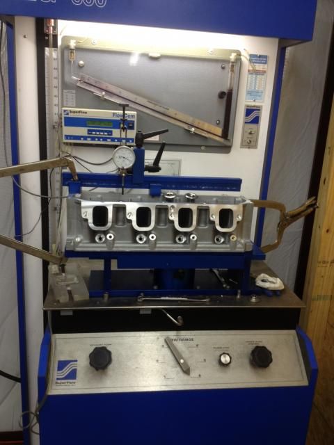
We have received our LT1 castings from GM and have already flowed/torn down and started grinding on them. Overall we should have numbers very soon.
Our before numbers were as follows:
Was flowed on a 4.060 bore at 28" of water with a Untouched port and valve job.
lift Intake Exhaust
.200 134 120
.300 204 164
.400 258 193
.500 291 204
.600 285 208
.650 291 210
And now for some pictures
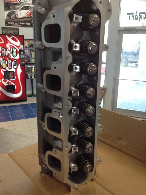
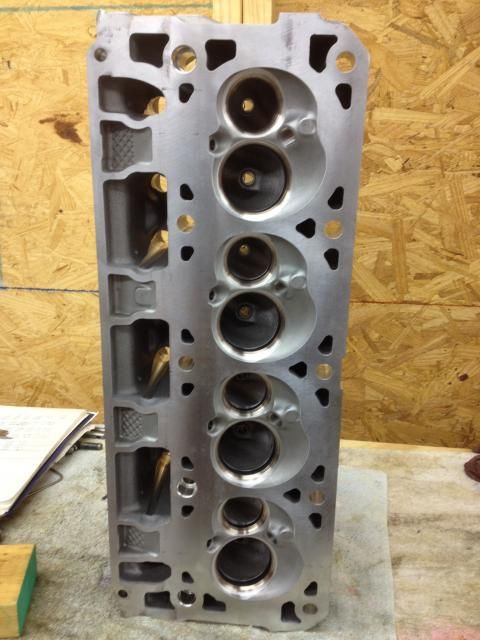
And now the fun part begins!
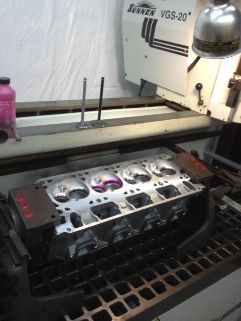
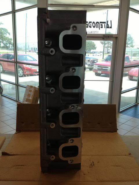
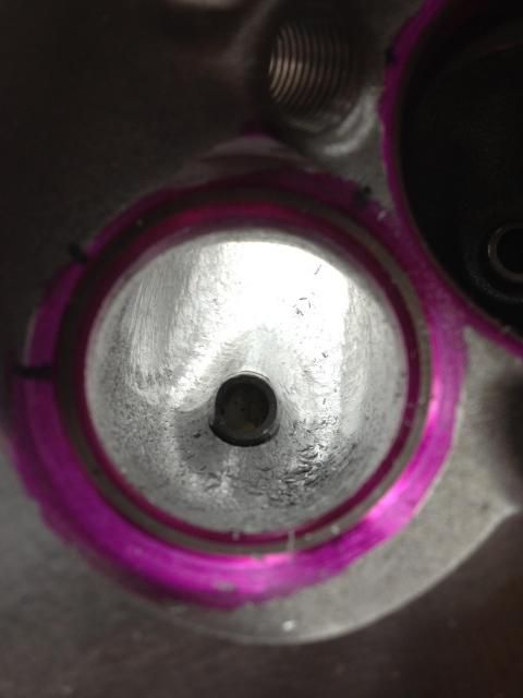
Roughed in Exhaust port
Our before numbers were as follows:
Was flowed on a 4.060 bore at 28" of water with a Untouched port and valve job.
lift Intake Exhaust
.200 134 120
.300 204 164
.400 258 193
.500 291 204
.600 285 208
.650 291 210
And now for some pictures
And now the fun part begins!
Roughed in Exhaust port
 07-12-2013, 06:27 PM
#3
Teching In

Join Date: May 2013
Posts: 41
Likes: 0
Received 0 Likes
on
0 Posts
^ please see my thread on this topic https://ls1tech.com/forums/advanced-...on-system.html
You need to consider tumble & swirl motion on a DI head as well as flow.
You need to consider tumble & swirl motion on a DI head as well as flow.
07-13-2013, 06:25 PM
#4
TECH Regular

Join Date: Aug 2003
Location: Texas
Posts: 483
Likes: 0
Received 0 Likes
on
0 Posts

I don't think I need to consider tumble swirl motion or cross tumble. All goes out the window once the valves are closed and it begins the compression stroke. Main factors will be chamber shape and piston profile shape. Im sure a flat faced or dished valve will have an effect as well. We'll see once results are out..I could be wrong 
They angled that exhaust port mostly for packaging imo..its kind of in the way.... The valve layout is like a SBF now
They angled that exhaust port mostly for packaging imo..its kind of in the way.... The valve layout is like a SBF now


 07-15-2013, 12:03 PM
#7
Closed ex-Sponsor Account
Thread Starter
Join Date: Jan 2012
Posts: 122
Likes: 0
Received 0 Likes
on
0 Posts
Updated flow numbers (still not finished)
Lift Intake/Exhaust
.200 137/116
.300 208/154
.400 270/197
.500 310/228
.600 331/245
.650 335/252
.700 340/257
.800 345/260
Still have quite a bit more development to do, this was first attempt.
Lift Intake/Exhaust
.200 137/116
.300 208/154
.400 270/197
.500 310/228
.600 331/245
.650 335/252
.700 340/257
.800 345/260
Still have quite a bit more development to do, this was first attempt.
Trending Topics
07-15-2013, 06:19 PM
#8
TECH Regular
iTrader: (8)
Join Date: May 2002
Location: Tampa FL
Posts: 429
Likes: 0
Received 0 Likes
on
0 Posts

Hmm, watching with great interest. As tall as that intake port looks in the pictures, I am really surprised it wasn't better out of the box at moving air, even though mixture motion was probably as big or bigger a focus than the airflow quantity.
07-15-2013, 07:01 PM
#9
Just because the port is high doesn't necisarrily mean that it will move more air. Alot has to be optimized to take advantage of that. There is absolutely zero short turn in these heads from the factory. Just a gradual slope to the valve. Combine that with a low velocity port and it doesn't surprise me it didn't move that much air out of the box.
 07-16-2013, 11:59 AM
#13
Closed ex-Sponsor Account
Thread Starter
Join Date: Jan 2012
Posts: 122
Likes: 0
Received 0 Likes
on
0 Posts
So in order for me to give you a answer i would need to know a Theoretical Maximum. What dictates this number? Is it left up to the person porting? So really this number your asking for could change depending on the person you ask. So to me, its irrelevant because it uses a variable that we cant account for, but i will calculate it for you sometime today if i get a chance.
Last edited by Late Model Racecraft; 07-16-2013 at 12:08 PM.
07-16-2013, 01:03 PM
#14
The " Discharge Coefficient " is the measure of how efficient a given area is in regards to volume flow verses area, divided by a theoretical maximum.
So in order for me to give you a answer i would need to know a Theoretical Maximum. What dictates this number? Is it left up to the person porting? So really this number your asking for could change depending on the person you ask. So to me, its irrelevant because it uses a variable that we cant account for, but i will calculate it for you sometime today if i get a chance.
So in order for me to give you a answer i would need to know a Theoretical Maximum. What dictates this number? Is it left up to the person porting? So really this number your asking for could change depending on the person you ask. So to me, its irrelevant because it uses a variable that we cant account for, but i will calculate it for you sometime today if i get a chance.
I simply posted that as a joke since there's two threads in here with shop's in Texas who have their hands on a new LT1 head and both put up stock flow numbers. Just goes to show that even something that should be reliable like flow numbers is subject to 'user discretion'.
07-16-2013, 02:46 PM
#15
TECH Veteran
iTrader: (12)
Join Date: Dec 2004
Location: Rockville, MD
Posts: 4,354
Likes: 0
Received 0 Likes
on
0 Posts
I simply posted that as a joke since there's two threads in here with shop's in Texas who have their hands on a new LT1 head and both put up stock flow numbers. Just goes to show that even something that should be reliable like flow numbers is subject to 'user discretion'.
we're getting to a point where CFD will be more important in creating a head that flows well AND is efficient. GM gained 30+ hp from a head that flows less, a cam that is slightly smaller, and a new injection system. working with the system and GM's improvements is probably going to be important for drivability, avg power, etc. the first dyno tests on teh 4? shops' heads will be very interesting me thinks. so will timing, fueling, and g/cyl readings.
 07-16-2013, 07:21 PM
#17
Teching In
Join Date: May 2013
Posts: 41
Likes: 0
Received 0 Likes
on
0 Posts
I don't think I need to consider tumble swirl motion or cross tumble. All goes out the window once the valves are closed and it begins the compression stroke. Main factors will be chamber shape and piston profile shape. Im sure a flat faced or dished valve will have an effect as well. We'll see once results are out..I could be wrong
On PFI, the fuel sprays on the back of a closed valve (closed valve injection) or on to an open valve, depending on the strategy employed at a given load point. Injector pulsewidths can max out at 15milliseconds and over 600 degrees. Charge motion isn't nearly as important on a PFI engine (relative to DI), which is why the LS7 style intake port can be very high flowing and still have good combustion.
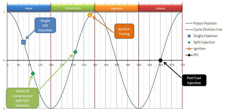
Here we see:
- a single GDI injection starting at 292 degrees BTDC compression/68CAD
- the first injection used during split injection: starting at 254 BTDC/106CAD
- the second injection used during split injection: starting at 80 BTDC/280CAD , fired in the compression stroke to create a stratified mixture
- Ignition timing: here I am showing 20 BTDC/340CAD
- Port fuel injection: for closed-valve injection, this occurs in the exhaust stroke, here ending at 450 BTDC compression /630 CAD
Note that the injection timing is set by SOI (Start of Injection) for DI and EOI (End of Injection) for PFI. On the PFI, fuel pressure is basically fixed, while on DI it can vary (although full power runs typically go at max fuel pressure).
Also, basically every production DI engine has a piston bowl rather than a flat top.
07-16-2013, 11:56 PM
#18
The theoretical maximum is dictated by physics. You have a given 'physical' valve flow area (circumference of the valve * Lift). When you put the head on the flow bench, you are putting a specified pressure drop across the port. For that physical valve flow area, you could calculate the flow rate based on the pressure differential using isentropic compressible flow equations.
Your measured flow will obviously be less than this 'ideal' airflow. For all intents and purposes, the ratio between the two is your discharge coefficient as you mentioned.
This is actually an easy calculation with the right equations. However, finding the right equations that are physically valid is not trivial. Personally, I tend to use the pressure ratio variant of the 'flow function'. I'm too tired to do the calc at the moment, but if I remember tomorrow I'll post it up. I was always curious what the Cd was on a stock vs. a modified port.
07-17-2013, 10:51 AM
#19
6600 rpm clutch dump of death Administrator
Good luck with the testing, please keep us posted.
I am interested in seeing if the modifications to heads improve peak power, but have a negative effect on low to midrange power. I understand the swirl and tumble are supposed to be important.
My guess (and this is only a guess) is that if you can improve the flow without removing any of the wings or vanes that create tumble and swirl, or radically reshape the port you might increase both raw flow without destroying the port. My guess is there is going to have to be some iterative testing to see what works and what does not work.
07-17-2013, 11:04 AM
#20
Closed ex-Sponsor Account
Thread Starter
Join Date: Jan 2012
Posts: 122
Likes: 0
Received 0 Likes
on
0 Posts
Good luck with the testing, please keep us posted.
I am interested in seeing if the modifications to heads improve peak power, but have a negative effect on low to midrange power. I understand the swirl and tumble are supposed to be important.
My guess (and this is only a guess) is that if you can improve the flow without removing any of the wings or vanes that create tumble and swirl, or radically reshape the port you might increase both raw flow without destroying the port. My guess is there is going to have to be some iterative testing to see what works and what does not work.
I am interested in seeing if the modifications to heads improve peak power, but have a negative effect on low to midrange power. I understand the swirl and tumble are supposed to be important.
My guess (and this is only a guess) is that if you can improve the flow without removing any of the wings or vanes that create tumble and swirl, or radically reshape the port you might increase both raw flow without destroying the port. My guess is there is going to have to be some iterative testing to see what works and what does not work.