
Build Thread: 376ci Iron Block
 03-25-2012, 02:00 PM
#1

It’s been just over a year since I took the old engine out of my 2000 Pontiac Trans Am to freshen it up. It had 182k miles on the clock and started to show oil pressure issues, so I felt a rebuild was needed. What was supposed to be just a quick rebuild with rings and bearings, turned into a 7 month project machining a new engine from scratch. At the request of a few friends, I’m posting a build thread to chronicle the endeavor now that the car is up and running again.
Part 1: The Block
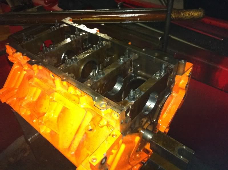
The foundation for the new build was a 6.0L iron block I found on craigslist. It was powder coated orange, which wouldn’t have been my first choice in color, but it was in really good shape and the price was right. After checking the mains, the bores were a little inconsistent and a little loose, so a line hone was first on the To-Do list. When I finished, they all measured 2.7509”-2.7510”.
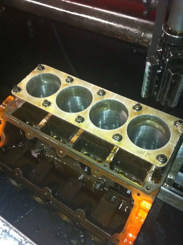
After the line hone, the block was loaded up in a Sunnen CK-10 cylinder hone, the torque plate was bolted on, and the bores were honed from 4.0” to 4.065”, plus or minus a few tenths to match each piston. I used a really rough grit to take out the material quickly, stepped up to a smoother grit to get closer to final bore size, and then finished the plateau hone with an even smoother stone.
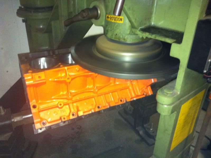
With the cylinders straight and round, it was time to clean up the deck. I had already mocked up a piston at each corner of the engine to measure how far the piston came out and how square the deck was. The pistons came out more than I had expected, and after cutting the deck to get it straight and flat, the pistons ended up .026” out of the hole. With the GM LS3 head gaskets, it would have put the quench distance too tight for my liking so a quick .013” was milled off the piston tops. Problem solved.
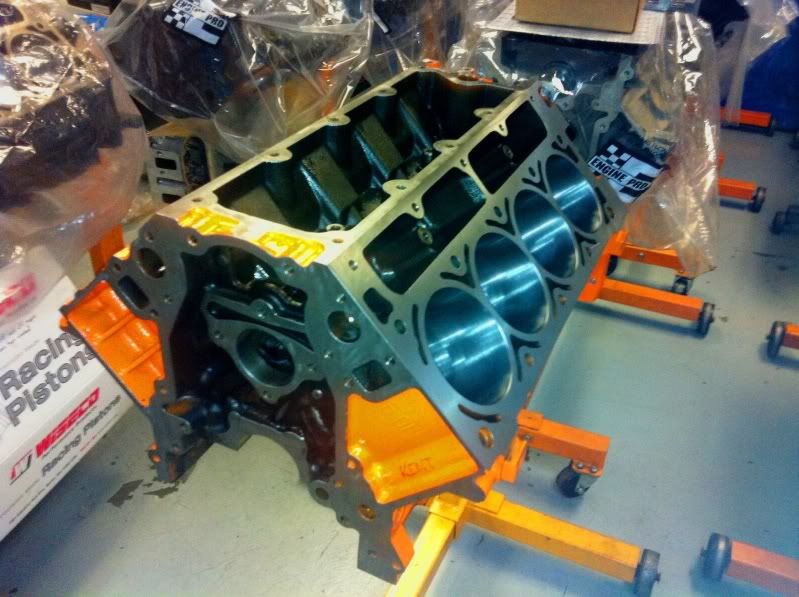
After buffing off the excess powder coating, the block was deburred and thoroughly cleaned of debris and foreign material with a pressure washer, then lightly coated with WD40 to prevent the machined surfaces from rusting. I also cleaned the cylinders alternating between acetone and ATF. You can clean the cylinders with acetone until the paper towels come out white and ATF will still pull honing grit out that would have otherwise embedded in the piston rings.
Part 1: The Block
The foundation for the new build was a 6.0L iron block I found on craigslist. It was powder coated orange, which wouldn’t have been my first choice in color, but it was in really good shape and the price was right. After checking the mains, the bores were a little inconsistent and a little loose, so a line hone was first on the To-Do list. When I finished, they all measured 2.7509”-2.7510”.
After the line hone, the block was loaded up in a Sunnen CK-10 cylinder hone, the torque plate was bolted on, and the bores were honed from 4.0” to 4.065”, plus or minus a few tenths to match each piston. I used a really rough grit to take out the material quickly, stepped up to a smoother grit to get closer to final bore size, and then finished the plateau hone with an even smoother stone.
With the cylinders straight and round, it was time to clean up the deck. I had already mocked up a piston at each corner of the engine to measure how far the piston came out and how square the deck was. The pistons came out more than I had expected, and after cutting the deck to get it straight and flat, the pistons ended up .026” out of the hole. With the GM LS3 head gaskets, it would have put the quench distance too tight for my liking so a quick .013” was milled off the piston tops. Problem solved.
After buffing off the excess powder coating, the block was deburred and thoroughly cleaned of debris and foreign material with a pressure washer, then lightly coated with WD40 to prevent the machined surfaces from rusting. I also cleaned the cylinders alternating between acetone and ATF. You can clean the cylinders with acetone until the paper towels come out white and ATF will still pull honing grit out that would have otherwise embedded in the piston rings.
 03-25-2012, 02:07 PM
#2
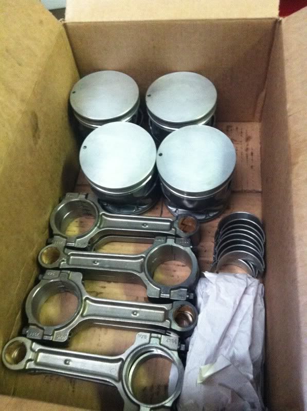
Part 2: The Rotating Assembly
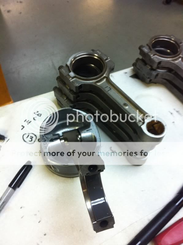
Since I’m not aiming to make 1000whp or go 200MPH at the Mile, I felt OEM components were more than adequate to hold the power goals I had in mind, but they would need some work. Pistons and rods came from a low mile LS3 and the crank came from an LS1 with the 24x reluctor wheel.
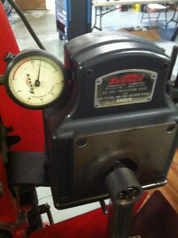
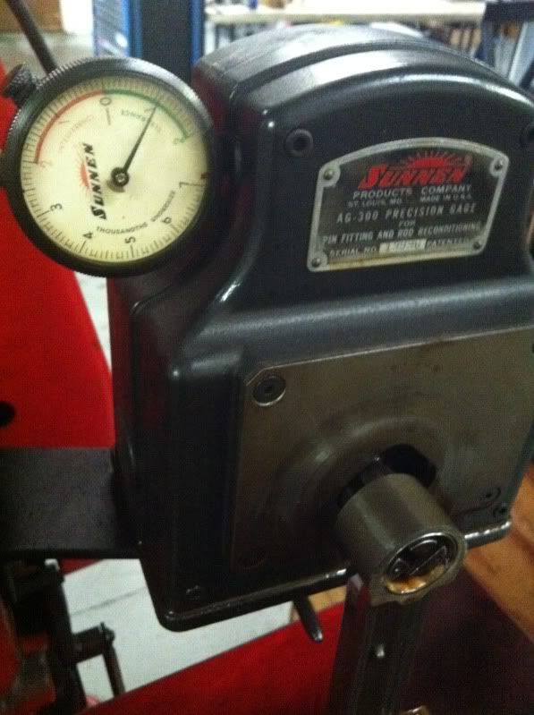
I already mentioned the pistons were milled, but the pin bores also needed work. Both the rods and pistons had a pin clearance of .0006”, which I felt was too tight. A couple minutes with the rod resizer put the clearance at .0011”.
Before:
After:
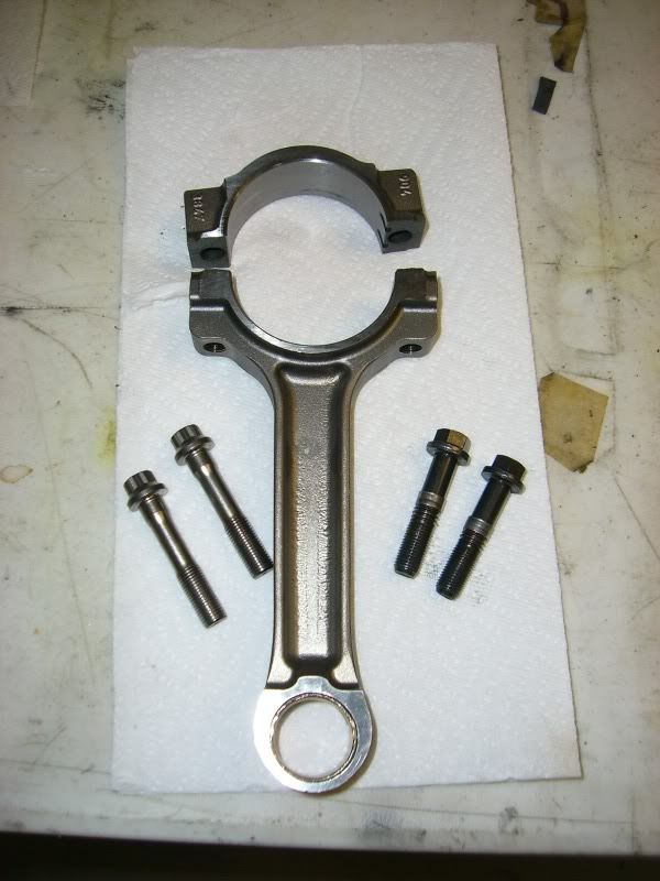
Even though the LS3 rods have the better rod bolts, I still decided to use ARP 2000 series rod bolts. With the ARP 2000 material having even higher tensile than the ARP 8740, I fully expected enough bore distortion to require a resize. With the OEM bolts, the bores all measured right at 2.2247” which is the low side of the allowable tolerance. With the ARP’s, the bores actually opened up to 2.2252”, which is as loose as you can go while still being within the allowable range of tolerance! I usually don’t like to run on the loose side of the tolerance in order to maximize bearing crush, but being able to use an ACL Race bearing rather than a passenger car bearing was worth it. The ACL Race bearings have a higher crush than passenger car bearings anyways, so I felt it would be perfectly acceptable.
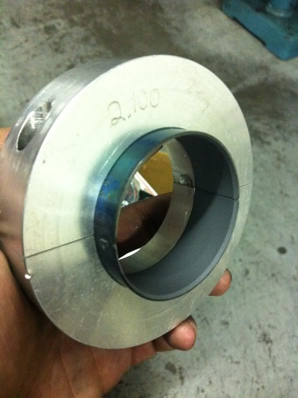
At this point, I should be content in running the ACL Race bearing, but I just couldn’t leave well enough alone. I wanted to narrow the rods bearings to reduce friction. I went through the bearing catalog and looked for the narrowest bearing I could find in an engine that is known to make respectable power. The Toyota 2JZGTE in the Supras use a .760” wide rod bearing, and everyone knows how much power those are capable of, but another potent little engine is the Nissan SR20 which uses an even narrower .669” wide rod bearing. What do I do? I turn them down to .630” wide and then chamfer them. Not the most scientific method I know, but it’s worked so far…
Before:
After:
Since I’m not aiming to make 1000whp or go 200MPH at the Mile, I felt OEM components were more than adequate to hold the power goals I had in mind, but they would need some work. Pistons and rods came from a low mile LS3 and the crank came from an LS1 with the 24x reluctor wheel.
I already mentioned the pistons were milled, but the pin bores also needed work. Both the rods and pistons had a pin clearance of .0006”, which I felt was too tight. A couple minutes with the rod resizer put the clearance at .0011”.
Before:
After:
Even though the LS3 rods have the better rod bolts, I still decided to use ARP 2000 series rod bolts. With the ARP 2000 material having even higher tensile than the ARP 8740, I fully expected enough bore distortion to require a resize. With the OEM bolts, the bores all measured right at 2.2247” which is the low side of the allowable tolerance. With the ARP’s, the bores actually opened up to 2.2252”, which is as loose as you can go while still being within the allowable range of tolerance! I usually don’t like to run on the loose side of the tolerance in order to maximize bearing crush, but being able to use an ACL Race bearing rather than a passenger car bearing was worth it. The ACL Race bearings have a higher crush than passenger car bearings anyways, so I felt it would be perfectly acceptable.
At this point, I should be content in running the ACL Race bearing, but I just couldn’t leave well enough alone. I wanted to narrow the rods bearings to reduce friction. I went through the bearing catalog and looked for the narrowest bearing I could find in an engine that is known to make respectable power. The Toyota 2JZGTE in the Supras use a .760” wide rod bearing, and everyone knows how much power those are capable of, but another potent little engine is the Nissan SR20 which uses an even narrower .669” wide rod bearing. What do I do? I turn them down to .630” wide and then chamfer them. Not the most scientific method I know, but it’s worked so far…
Before:
After:
03-25-2012, 02:28 PM
#3
Part 3: Assembling the Shortblock
The first step to assemble the shortblock is installing the camshaft. With the Durabond CH-23 cam bearings installed, it was found that there was as little as .0005” clearance in some bearing bores. In my experience, I’ve found this to be fairly common and will usually cause a tight fit when the cam is installed. If left alone, it will cause excess friction and can even spin bearings. To fix it, I went to a local crank grinder and had the camshaft journals ground and polished to achieve .003” clearance on all 5 journals. With the cam in and spinning freely, I could move on to the crank.
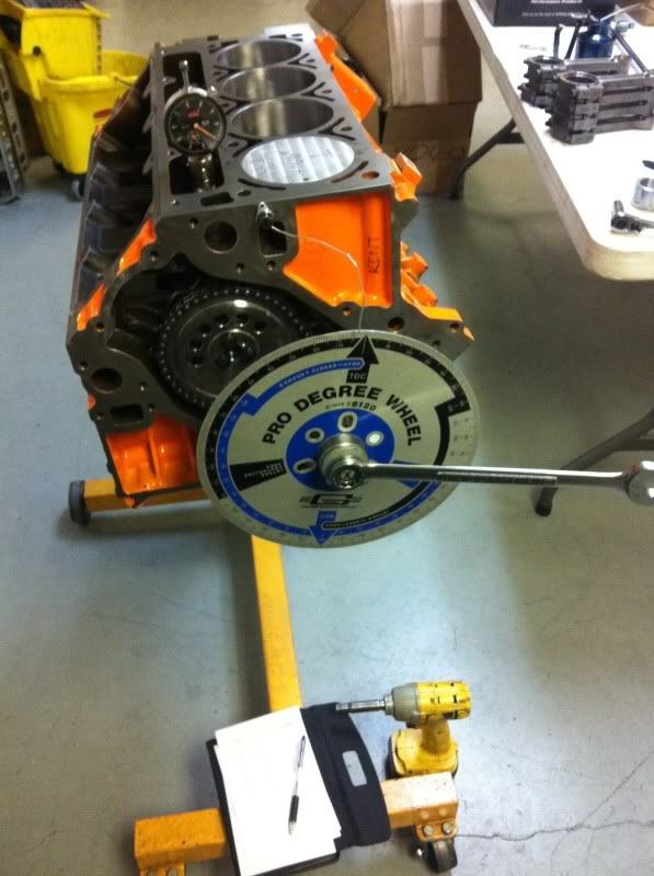
ACL Race bearings were again used in the main bores, with a combination of STD and X sizes to achieve .0023-.0025” bearing clearance. After a thorough final cleaning, the crankshaft was lowered in and lubed with 10w30 motor oil, the caps were installed, and after setting the thrust, the OEM main bolts were torqued to spec. The N-Motion billet single roller timing set went on next with ARP bolts, and set at 0 so there was no additional advance or retard in the cam timing. With the #1 rod and piston was installed, I found TDC and continued on to degree in the camshaft. Interestingly enough, what was supposed to be an old MTI V1 grind, turned out to be a single pattern 235°/235° duration cam…
To finish off the shortblock, a Melling M10296 oil pump was installed with the blue spring, new LS7 lifters, and after all of the covers and oil pan went on, a Powerbond 25% underdrive pulley was installed with an ARP crank bolt torqued to 240ft-lbs.
The first step to assemble the shortblock is installing the camshaft. With the Durabond CH-23 cam bearings installed, it was found that there was as little as .0005” clearance in some bearing bores. In my experience, I’ve found this to be fairly common and will usually cause a tight fit when the cam is installed. If left alone, it will cause excess friction and can even spin bearings. To fix it, I went to a local crank grinder and had the camshaft journals ground and polished to achieve .003” clearance on all 5 journals. With the cam in and spinning freely, I could move on to the crank.
ACL Race bearings were again used in the main bores, with a combination of STD and X sizes to achieve .0023-.0025” bearing clearance. After a thorough final cleaning, the crankshaft was lowered in and lubed with 10w30 motor oil, the caps were installed, and after setting the thrust, the OEM main bolts were torqued to spec. The N-Motion billet single roller timing set went on next with ARP bolts, and set at 0 so there was no additional advance or retard in the cam timing. With the #1 rod and piston was installed, I found TDC and continued on to degree in the camshaft. Interestingly enough, what was supposed to be an old MTI V1 grind, turned out to be a single pattern 235°/235° duration cam…
To finish off the shortblock, a Melling M10296 oil pump was installed with the blue spring, new LS7 lifters, and after all of the covers and oil pan went on, a Powerbond 25% underdrive pulley was installed with an ARP crank bolt torqued to 240ft-lbs.
03-25-2012, 03:37 PM
#4
Part 4: The Cylinder Heads
Now that the LSx engines have been around for about 15 years, there is a great selection of cylinder heads on the market from CNC ported OEM castings to all out canted valve race heads. With the larger bore, I could even utilize a big valve LS3 head, but admittedly I’m more biased towards the cathedral port heads. Keeping the OEM theme, my first choice then was the 243/799 castings like what you could find on 4.8L/5.3L truck engines, LS2 GTO’s and Vette’s, and even the 5.7L C5 Z06. I happened to find a set for a good price, but upon disassembly, I found a few problems with the valve guides…
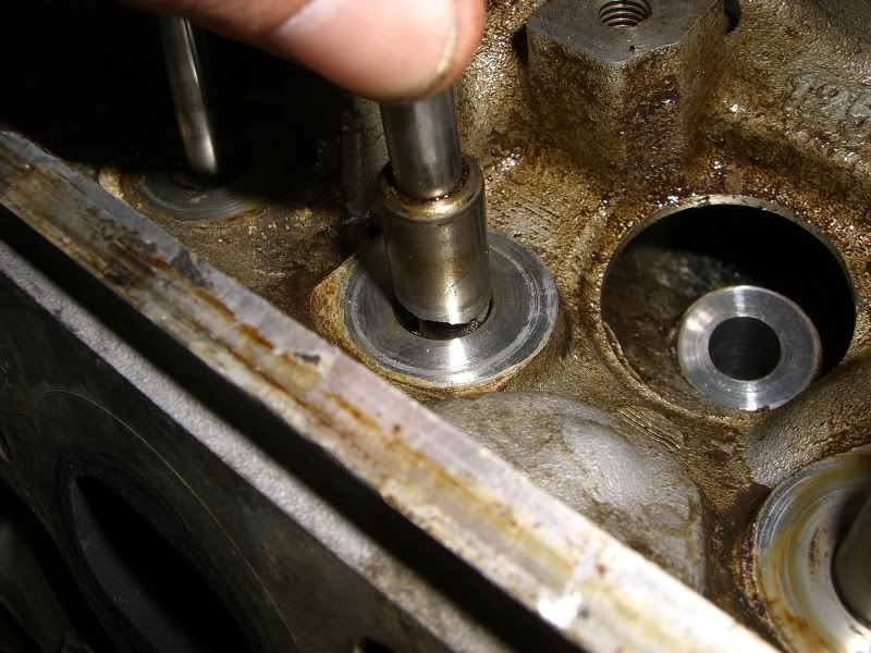
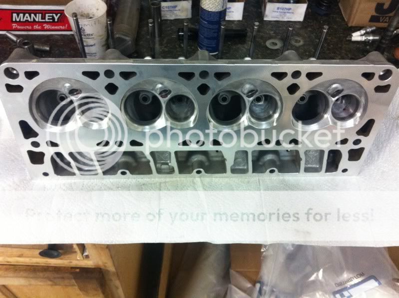
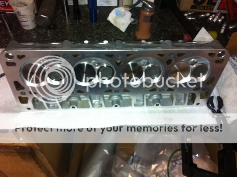
In the interest of time, I shelved the 243 heads and decided to see what the 241’s that I already had were capable of. Sitting in the garage were a set of 2.02” Ferrea intake and 1.60” Manley exhaust valves that were never put to good use, so they would replace the smaller OEM valves that came in the heads. After cleaning the heads up, they were loaded up in the Sunnen VGS-20 and treated to a fresh new valve job for the larger valves.
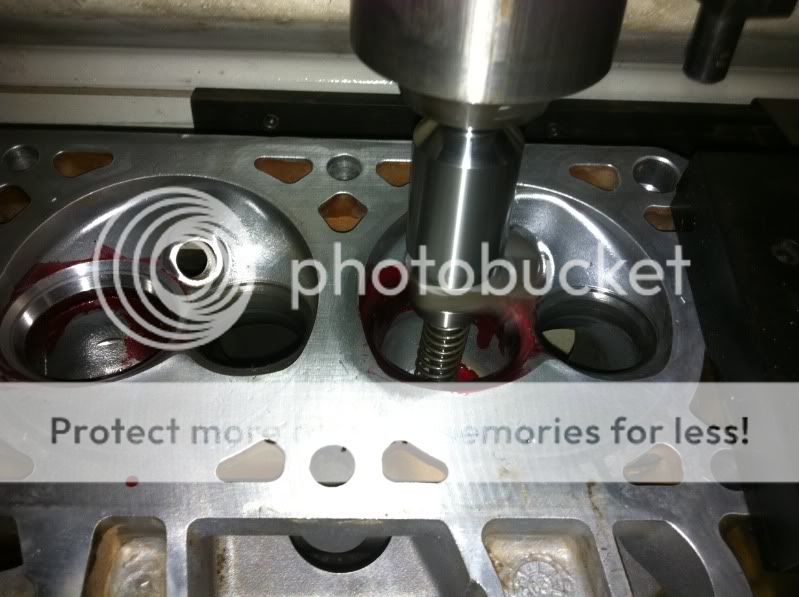
Instead of the typical 30°-45°-60° three angle “high performance” valve job many performance shops like to use, I used profiles with a little steeper top cut, the same 45° degree seat, and a steeper bottom cut on the intake and a shallower bottom cut on the exhaust. It’s worked out well in the past, so I knew it would work well here too. I finished up with a 70° bowl cut and before taking them off to finish them up with the grinder.
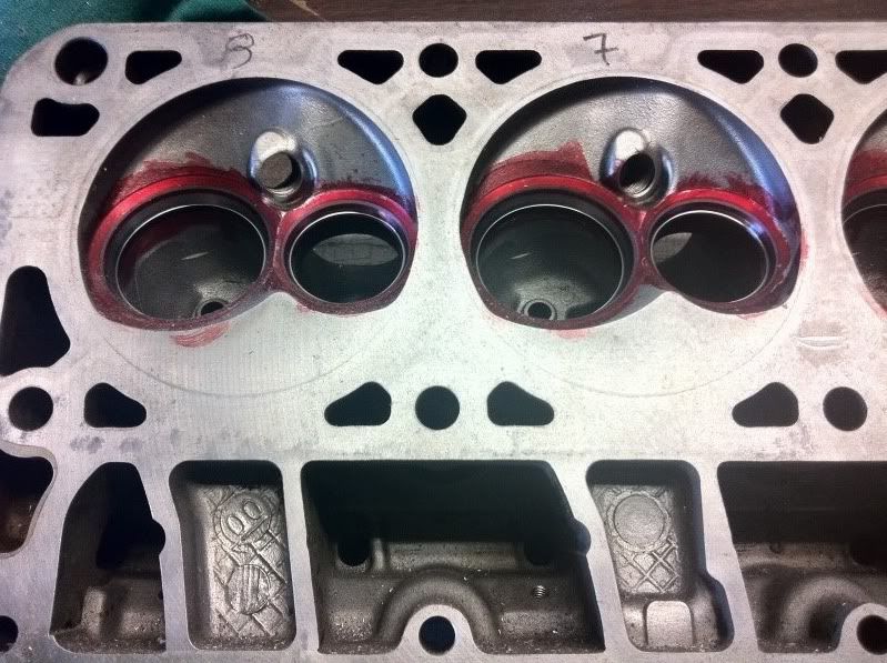
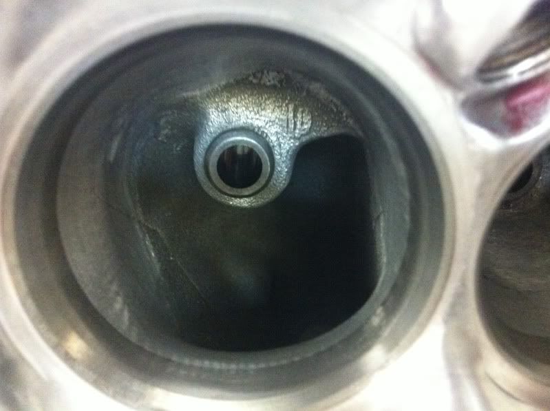
They say that 90% of your gains are 1” above and below the valve seat, so I decided to put that theory to the test. After the valve job, the top cut was blended into the rest of the chamber, the bowls were blended in and that’s it. The grinder never touched anything above the valve guide on neither the intake or exhaust port.
Intake
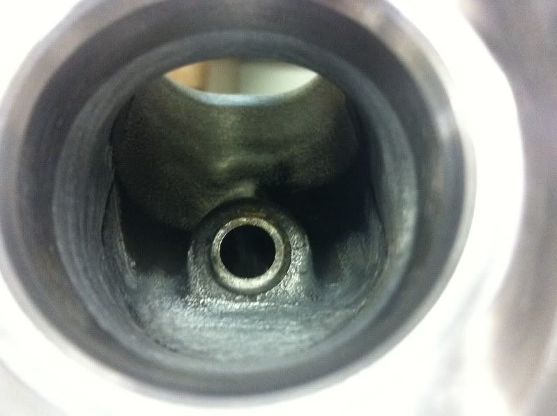
Exhaust
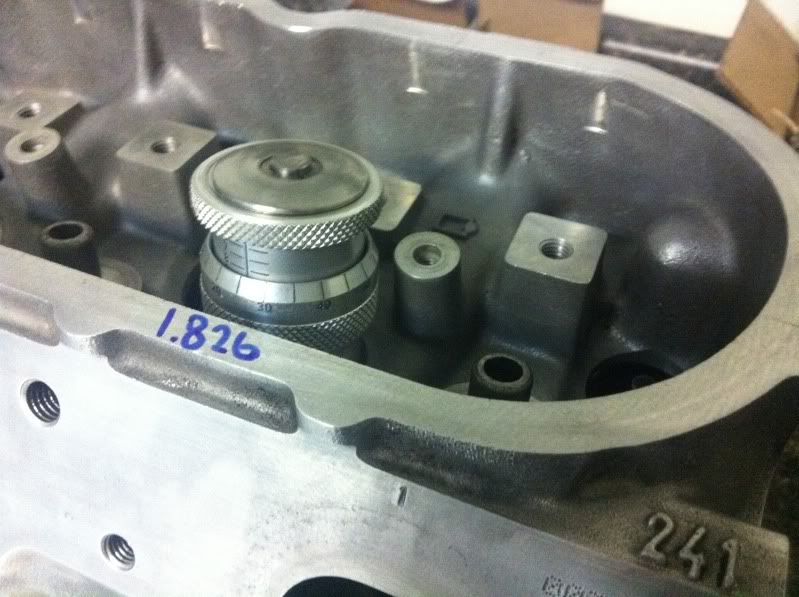
With the new valve job, the valves were sunk into the heads a little more, which resulted in a larger installed height. Instead of a typical 1.80” installed height; I was measuring 1.82x” range putting my springs over .100” from coilbind when the valve was fully opened. Shimming up the springs up to .060” from coilbind is standard, and put my dual springs at 450lbs open, so that’s where they ended up. The rest of the valves were installed with new seals, titanium retainers, and OEM locks.
Now that the LSx engines have been around for about 15 years, there is a great selection of cylinder heads on the market from CNC ported OEM castings to all out canted valve race heads. With the larger bore, I could even utilize a big valve LS3 head, but admittedly I’m more biased towards the cathedral port heads. Keeping the OEM theme, my first choice then was the 243/799 castings like what you could find on 4.8L/5.3L truck engines, LS2 GTO’s and Vette’s, and even the 5.7L C5 Z06. I happened to find a set for a good price, but upon disassembly, I found a few problems with the valve guides…
In the interest of time, I shelved the 243 heads and decided to see what the 241’s that I already had were capable of. Sitting in the garage were a set of 2.02” Ferrea intake and 1.60” Manley exhaust valves that were never put to good use, so they would replace the smaller OEM valves that came in the heads. After cleaning the heads up, they were loaded up in the Sunnen VGS-20 and treated to a fresh new valve job for the larger valves.
Instead of the typical 30°-45°-60° three angle “high performance” valve job many performance shops like to use, I used profiles with a little steeper top cut, the same 45° degree seat, and a steeper bottom cut on the intake and a shallower bottom cut on the exhaust. It’s worked out well in the past, so I knew it would work well here too. I finished up with a 70° bowl cut and before taking them off to finish them up with the grinder.
They say that 90% of your gains are 1” above and below the valve seat, so I decided to put that theory to the test. After the valve job, the top cut was blended into the rest of the chamber, the bowls were blended in and that’s it. The grinder never touched anything above the valve guide on neither the intake or exhaust port.
Intake
Exhaust
With the new valve job, the valves were sunk into the heads a little more, which resulted in a larger installed height. Instead of a typical 1.80” installed height; I was measuring 1.82x” range putting my springs over .100” from coilbind when the valve was fully opened. Shimming up the springs up to .060” from coilbind is standard, and put my dual springs at 450lbs open, so that’s where they ended up. The rest of the valves were installed with new seals, titanium retainers, and OEM locks.
Last edited by KCS; 04-01-2012 at 08:06 AM.
03-25-2012, 04:23 PM
#5
Part 5: Installation and Dyno Tune
With the shortblock and cylinder heads complete, it was time to finish up the longblock before getting the engine back into the car. The heads went on with OEM MLS headgaskets and ARP head bolts. PTV was a little tight on the intake side, but acceptable. TSP 5/16” pushrods were installed after checking preload, topped with the stock steel rocker arms.
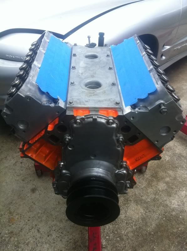
With the engine back in the car, everything was bolted back on to get ready to fire up. An LS6 clutch and '01 up slave went on in front of the T56 and aluminum driveshaft. The old MTI lid went back on with the stock LS1 intake, throttle body, and injectors. The SLP 1-3/4" longtubes were bolted up with dummy cats, y-pipe, and Loudmouth exhaust. NGK TR5's, MSD wires, and the stock coils were the last to be installed.
The engine fired up right away with 60psi of oil pressure. There were no leaks and no weird noises. After putting about 50 miles on the engine, I headed out to Victoria for an appointment with Patrick Guerra. A few issues arose on the way there, but with Kurt there, he quickly got me lined out and the car went on the dyno.
Once Patrick built the tune and sorted out the low speed driveability, it was time to make the first WOT pull. It did not go the way I expected…
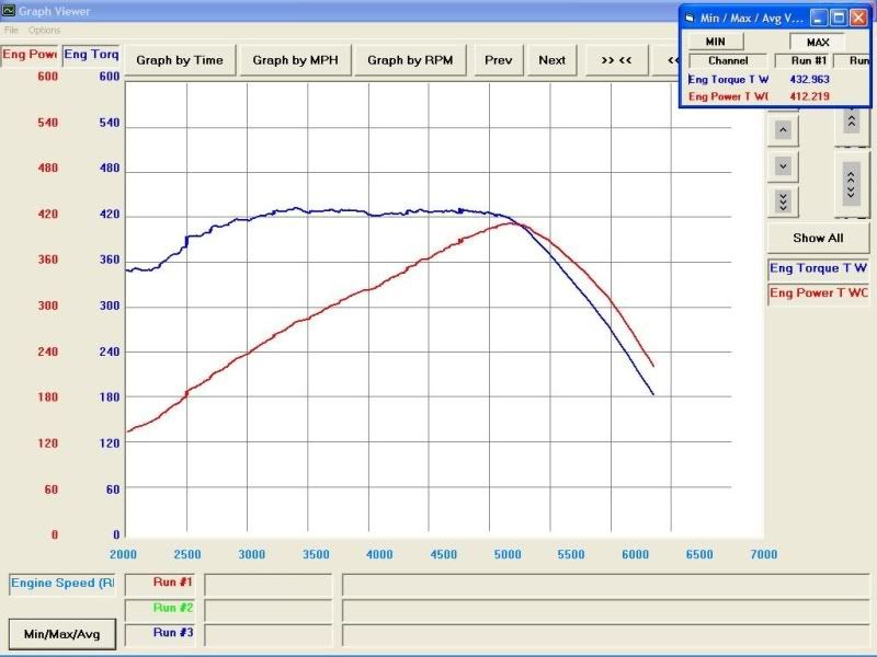
At about 5000RPM, the clutch slips and the engine shoots up to the rev limiter. Another pull ends with the same result. Patrick then puts it in 2nd gear to see if it will hold out a little longer, even though the acceleration rate will show lower numbers, but it still slips.

So even though the engine is built and running well, I'm still not finished. I'm looking into possible causes and solutions to the clutch, and working the next round of modifications. If I don't go forward with the 243's, I'll probably go with a set of LS3 heads and a smaller cam. That LS1 manifold has got to go anyways. I'll keep this thread updated as things progress.
With the shortblock and cylinder heads complete, it was time to finish up the longblock before getting the engine back into the car. The heads went on with OEM MLS headgaskets and ARP head bolts. PTV was a little tight on the intake side, but acceptable. TSP 5/16” pushrods were installed after checking preload, topped with the stock steel rocker arms.
With the engine back in the car, everything was bolted back on to get ready to fire up. An LS6 clutch and '01 up slave went on in front of the T56 and aluminum driveshaft. The old MTI lid went back on with the stock LS1 intake, throttle body, and injectors. The SLP 1-3/4" longtubes were bolted up with dummy cats, y-pipe, and Loudmouth exhaust. NGK TR5's, MSD wires, and the stock coils were the last to be installed.
The engine fired up right away with 60psi of oil pressure. There were no leaks and no weird noises. After putting about 50 miles on the engine, I headed out to Victoria for an appointment with Patrick Guerra. A few issues arose on the way there, but with Kurt there, he quickly got me lined out and the car went on the dyno.
Once Patrick built the tune and sorted out the low speed driveability, it was time to make the first WOT pull. It did not go the way I expected…
At about 5000RPM, the clutch slips and the engine shoots up to the rev limiter. Another pull ends with the same result. Patrick then puts it in 2nd gear to see if it will hold out a little longer, even though the acceleration rate will show lower numbers, but it still slips.
So even though the engine is built and running well, I'm still not finished. I'm looking into possible causes and solutions to the clutch, and working the next round of modifications. If I don't go forward with the 243's, I'll probably go with a set of LS3 heads and a smaller cam. That LS1 manifold has got to go anyways. I'll keep this thread updated as things progress.
03-25-2012, 04:48 PM
#7
On The Tree
iTrader: (1)

Join Date: Dec 2010
Location: Ft. Worth
Posts: 133
Likes: 0
Received 0 Likes
on
0 Posts
Nicely done! Thanks for sharing...
Not bad results at all for a first pull in IMO.
Extremely flat (and fat) torque curve.
Not real good clutch results though.
Maybe a longer bed in will help...
Did you really HONE it 65 thou? or was it bored then honed?
Not bad results at all for a first pull in IMO.
Extremely flat (and fat) torque curve.
Not real good clutch results though.
Maybe a longer bed in will help...
Did you really HONE it 65 thou? or was it bored then honed?
Last edited by technicalninja; 03-25-2012 at 04:52 PM. Reason: add question
Trending Topics
03-25-2012, 06:12 PM
#8
Yeah, I honed it all out. The rough stones actually took the material out pretty quickly. It wouldnt have been any faster to bore it and then hone it, so I just did it all on the hone. If it was something like taking a 5.3L block out to 3.905", then that would be bored first without a doubt.
 03-26-2012, 09:00 PM
#12
Thanks for all the kind words!
It was the clutch that was in the car before I took the old engine out. I was hesitant to reuse it, but I was really pressed for time and it did look to be in really good shape. I don't know if it's normal or not, but when the clutch does slip, the pedal falls to the floor and does not recover unless you pull it up.
It was the clutch that was in the car before I took the old engine out. I was hesitant to reuse it, but I was really pressed for time and it did look to be in really good shape. I don't know if it's normal or not, but when the clutch does slip, the pedal falls to the floor and does not recover unless you pull it up.
03-29-2012, 11:22 AM
#14
Right now, I'm driving it to and from work everyday. 400ft-lbs and a six speed are very therapeutic after a stressful day at work, lol.
03-29-2012, 11:59 AM
#15
TECH Resident
iTrader: (2)
Join Date: Sep 2010
Location: Salisbury, NC
Posts: 909
Likes: 0
Received 0 Likes
on
0 Posts
Im PMing you if my LS1 lets go. That thing is gorgeous and I want to do the same thing for my camaro. I know the orange may not have been the first choice for a trans am but Ive always wanted a chevy orange block in my 98 Z
03-31-2012, 09:32 AM
#17
Compression ended up right at 11:1 and the cam has a 110 LSA. I was really expecting more torque based on cubic inches and the compression, but I think it's being held back by the clutch. That torque curve is just too flat, like it hit a ceiling.
04-01-2012, 07:33 AM
#18
Launching!
iTrader: (6)

Join Date: Nov 2010
Location: northern indiana
Posts: 272
Likes: 0
Received 0 Likes
on
0 Posts
yeah,i definately think the clutch is causing issues,even before 5000rpm probably.still,that motor is making a lot of power early on.get that clutch issue fixed and the power will definately climb a lot more.and your right,most gains from porting,at least on the Gen3 heads,come from just under the valve seat.hard to tell from the pics,but looks like you could have opened up the bowls a little more,but nothing wrong with being a little conservative,you'll hit water quicker on the 241s than the 243s.hell,i wouldn't bother with another set of heads.just a Fast with a 90mm TB,or even an LS6,will show sizable gains over the LS1intake..thanks for sharing your build.a lot of newbs could learn from this,i say it should be a sticky..
04-01-2012, 08:03 AM
#19
yeah,i definately think the clutch is causing issues,even before 5000rpm probably.still,that motor is making a lot of power early on.get that clutch issue fixed and the power will definately climb a lot more.and your right,most gains from porting,at least on the Gen3 heads,come from just under the valve seat.hard to tell from the pics,but looks like you could have opened up the bowls a little more,but nothing wrong with being a little conservative,you'll hit water quicker on the 241s than the 243s.hell,i wouldn't bother with another set of heads.just a Fast with a 90mm TB,or even an LS6,will show sizable gains over the LS1intake..thanks for sharing your build.a lot of newbs could learn from this,i say it should be a sticky..
There wasn't much done in the bowls other than putting the throat diameter at 90% of the valve diameter and then blending it all in. The next set of heads are going to have an even larger valve, so right off the bat I'll be installing larger seats, but I'm taking my time on them. Next up is the clutch, then 1-7/8" headers and a different intake manifold.
04-01-2012, 09:02 AM
#20
Launching!
iTrader: (6)
Join Date: Nov 2010
Location: northern indiana
Posts: 272
Likes: 0
Received 0 Likes
on
0 Posts
Thanks again.
There wasn't much done in the bowls other than putting the throat diameter at 90% of the valve diameter and then blending it all in. The next set of heads are going to have an even larger valve, so right off the bat I'll be installing larger seats, but I'm taking my time on them. Next up is the clutch, then 1-7/8" headers and a different intake manifold.
There wasn't much done in the bowls other than putting the throat diameter at 90% of the valve diameter and then blending it all in. The next set of heads are going to have an even larger valve, so right off the bat I'll be installing larger seats, but I'm taking my time on them. Next up is the clutch, then 1-7/8" headers and a different intake manifold.
i'm saving up for my next toy,and my plan is to build a 6.0 and do basically what your doing.OEM heads,but with the right supporting mods.for somebody on a budget,the money is better spent on quality internals and machine work.the way i see it,why spend money on heads that flow way more air than needed for the HP goals.some very smart people have said you need just enough airflow to support your target HP,and no more.what's the ICL of your cam?IMO,most people go too big on the cam with too wide of a lobe seperation.better to go smaller with a tighter LSA to let the overlap to get the intake charge going.