When you click on links to various merchants on this site and make a purchase, this can result in this site earning a commission. Affiliate programs and affiliations include, but are not limited to, the eBay Partner Network.
To keep things simple and to make my life quicker while documenting and working, everything shown is being done on the passenger side. Everything is the same on the drivers side unless noted. I tore down the drivers side in about 1/4 of the time as the passenger side just from doing it again and not needing to take pictures and notes.
It's also a good idea to have a marker and sandwich bags close by. I bag and tag all bolts and small parts that come off the car, especially if they're going to be reused.
First thing I started with was removing the brakes. LT1 front calipers use (2) 3/8 alan/hex key bolts. I forget what LS1 calipers use but I have a set that came with the spindles, I'll check and update later for reference
After loosening the caliper bolts, I used a pry bar to pry the caliper off of the rotor. I then used a rubber mallet with one good hit to the back of the disk to knock it loose.
I'm keeping the old caliper hanging for now. I don't want to break the system open until I have most of the front end back together and the Brembo's and hoses ready to go.
Next was the tie rod end. Loosen the jam nut on the inner tie rod, I used an adjustable. Remove the cotter pin from the crown nut and break loose, nut is a 18mm.
After the nut is loose or off, put on a tie rod puller and break it loose. (these are cheap and definably worth it) Once the tie rod end is off, simply spin it off of the inner tie rod.
One thing to note is to keep a measurement on where these go. I'm getting an alignment after so I didn't go crazy with measuring but if you don't plan on getting an alignment, I would make some marks or some precise measurements to make sure the new one goes back exactly where the old one was.
I also bought new inner tie rods. After looking at mine, they don't seem like they need replacement so I may keep them and save the new ones for down the road if I need a new steering rack. I haven't decided on this yet.
Then it was time to get the spindles off. First thing I did was disconnect the ABS sensor and remove the 4 hub bolts, they're 13mm. One of the hub bolts was holding a bracket that keeps the ABS sensor wires from moving around, I plan to reuse it on the new spindles.
Then it was time to break the ball joints loose. Remove the cotter pins from the upper and lower ball joints. Then loosen but do not remove the crown nuts, upper ball joint is a 15mm, lower is a 24mm. I loosen the crown nuts until they're slightly past the end of the stud.
With the hub still on, sometimes the ABS plug can get in the way of the lower ball joint crown nut. I used a 24mm socket and a breaker bar to break it loose, then I used an adjustable to loosen.
To break the upper ball joint loose, I hit the top of the crown nut/stud with a hammer. After a couple swings, it popped out.
The lowers were a little more stubborn, they didn't break loose with a hammer. I ended up using a 2-jaw puller hooked onto the bottom of the spindle. It popped with a couple cranks.
Once the uppers and lowers are broken loose, loosen the crown nuts the rest of the way off and remove the spindle.
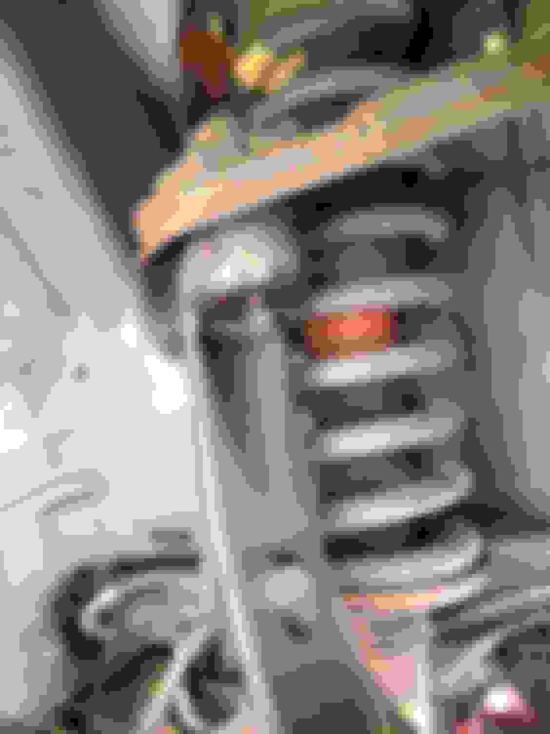
Next it's time to remove the spring/shock/upper control arm assembly. I loosen all the nuts and bolts before removing any, but once that's done I start with the bottom, which has (2) 13mm bolts that comes in from the bottom and a 15mm nut that sits on top of each.
Up top on the passenger side, there are (2) 13mm bolts and (2) 15mm nuts that require a deep socket. The AC lines get in the way of the two closest to the engine. A swivel helps but the one 13mm bolt I had to crank most of the way out with a wrench which was a real pain in the a**. For me, the passenger side took longer than the driver side.
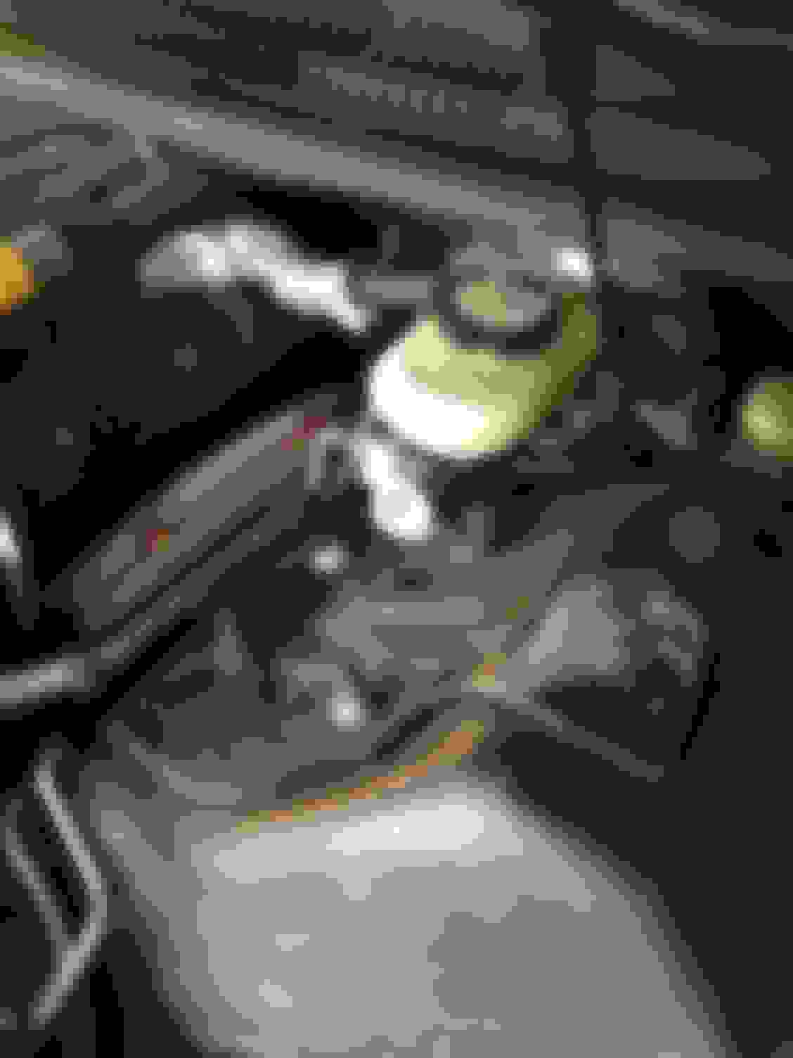
For the drivers side, there are (2) T50 star bit bolts and (2) 15mm nuts that require a deep socket. You don't need to remove the master, but you do need to remove the two nuts holding it to gain some wiggle room, there are (2) that are 15mm.
As mentioned before, moving around the master was much easier and quicker than moving around the AC lines on the passenger side.
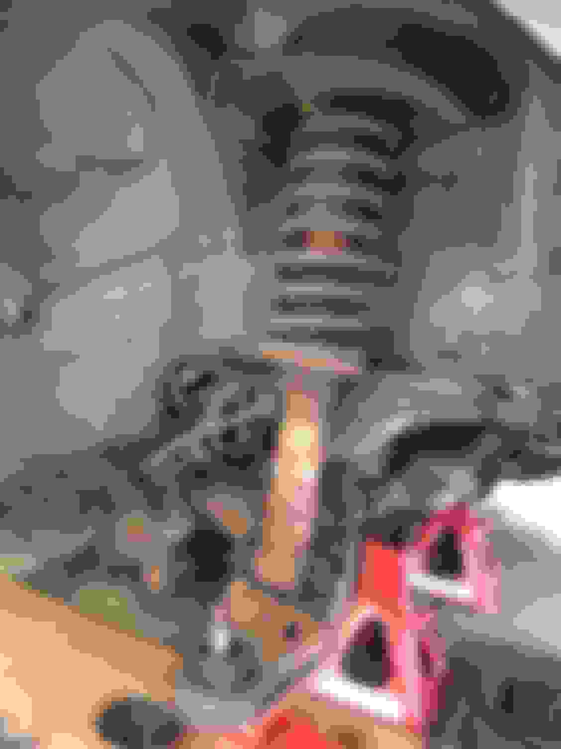
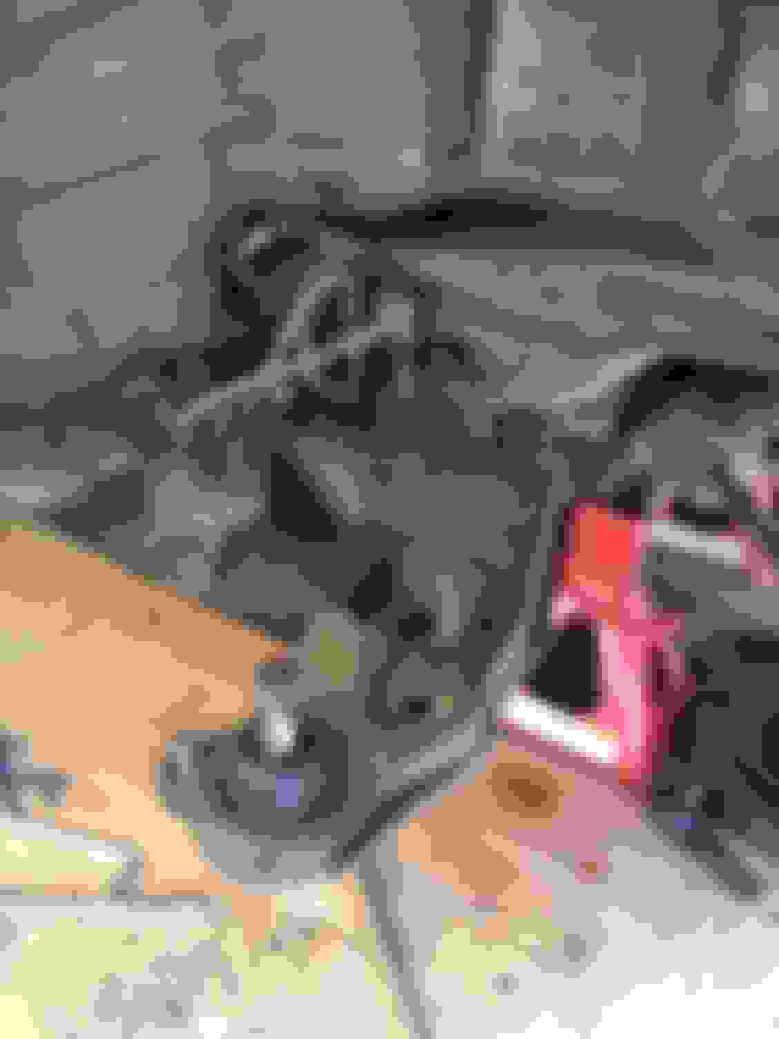
After all of the top and bottom nuts and bolts are removed, just remove the assembly buy pulling the bottom out and down.
Not the worst I've seen but still crusty.
Finally, time for the last part, the lower control arms. Both the front and rear alignment bolts are held in with 21mm nuts. No need to hold the bolts as they have tabs that keep them from spinning.
The front/horizontal bolts were pretty easy. To remove the bolt, turn the steering wheel locked to the opposite side that you're working on, otherwise the steering bellow/boot will get in the way of the bolt coming out.
As many people know, the rear/vertical bolts are hit and miss. They came out on the drivers side with a hammer and a punch, however, they were seized on the passenger side.
That was it for today. Tomorrow I'm going to cut out the passenger side bolt to remove the arm, wash, clean, prep, and paint the inner fender wells, and assemble my Koni shocks and BMR springs if I have time.
Nice work. I just did this exact thing last weekend. It's weird as I feel like I am doing it all over again. I had to cut all 4 of my lower control arm bolts out. The two vertical rear ones required me to have a diamond tip sawzall blade. It was like $15 for one blade but it was the only kind of blade that would cut through that hardened sleeve. Cutting fluid was helpful as well. Even with the diamond blade, the cutting is slow. Like 10min of actual cutting time on each side. If you have access to a torch, that would be the better way.
As mentioned before, one of the lower control arm bolts was frozen in the bushing, it was the passenger side, rear vertical bushing. After drenching it in penetrating fluid and a while of slugging it with a sledge, I decided to order some new bolts and cut this one out.
I ended up using a sawzall and a oscillating tool to cut it out.
The bottom of the bushing wasn't touching the bottom of the sub frame which allowed enough room for me to get a sawzall blade in there and cut just the bolt which went easy.
The harder part was the top of the bushing, which was in contact with sub frame so I had to cut through the bushing and bolt. This took a bit more time and effort and was a combination of the sawzall and oscillating tool. Once most of the bushing was cut, a hammer and wedge knocked the rest of it loose.
I also got around to washing the fender wells and liners today as well. Unfortunately due to the weather, I wasn't able to prep and paint the inner fenders.
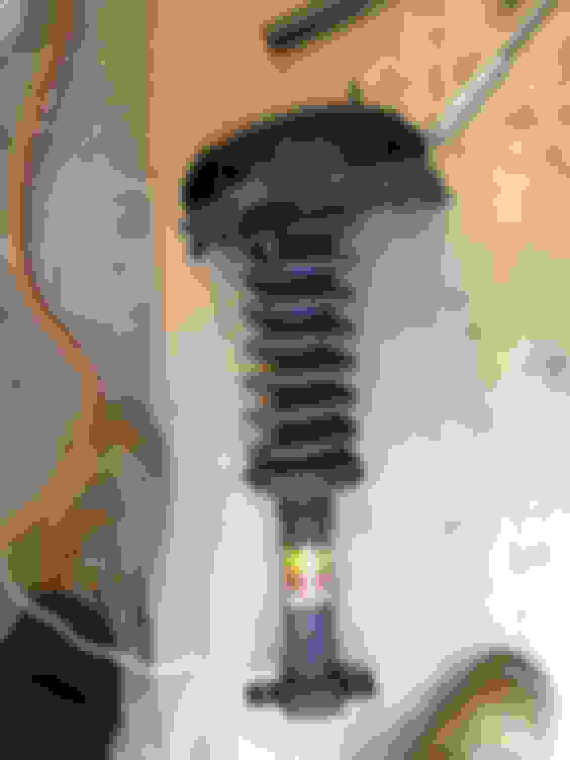
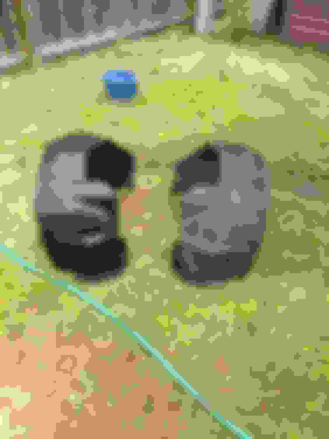
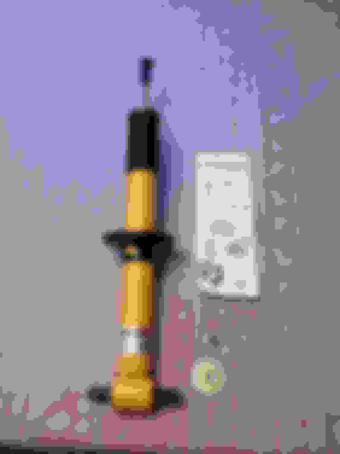
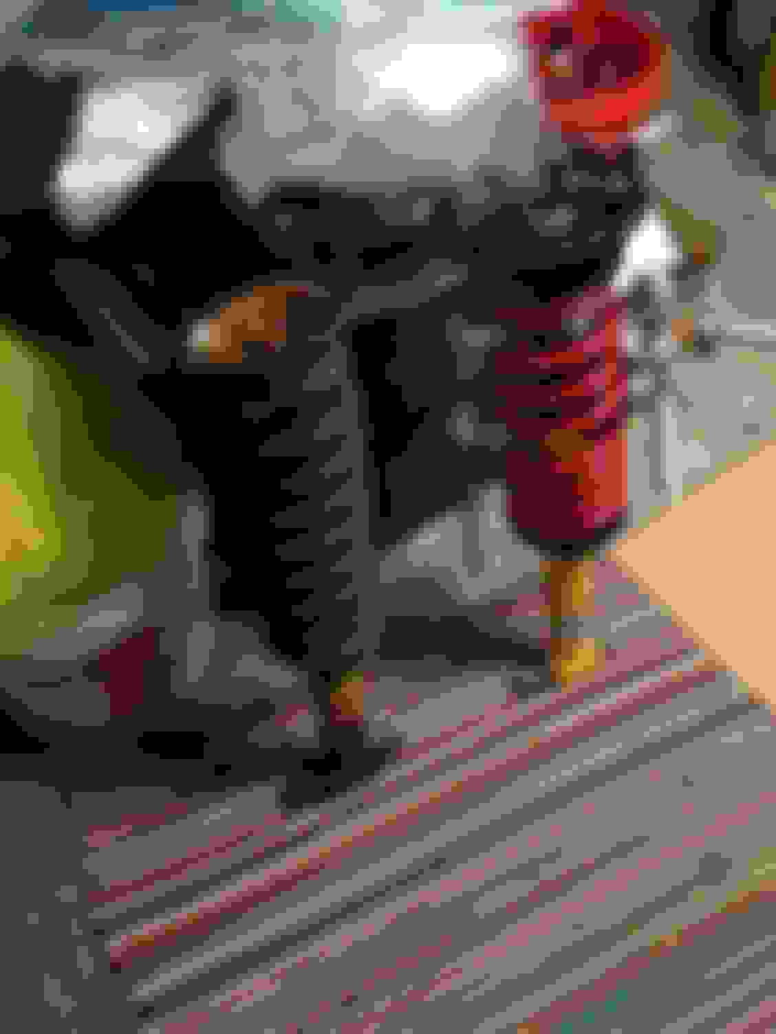
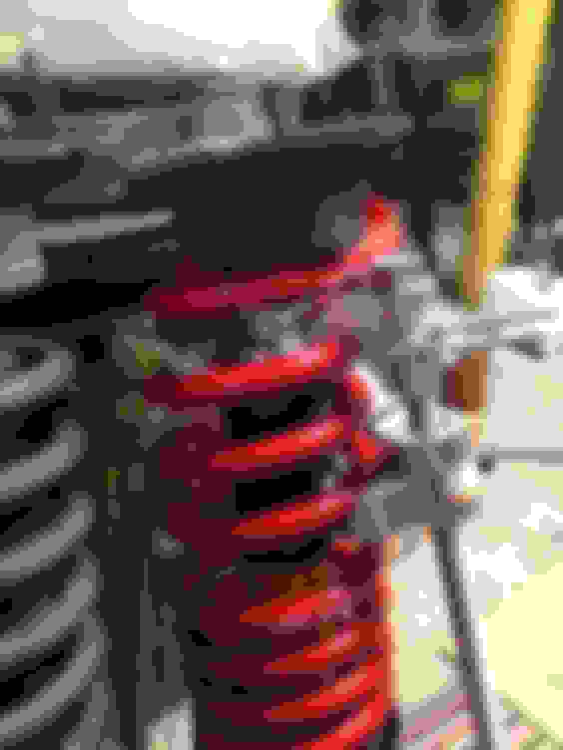
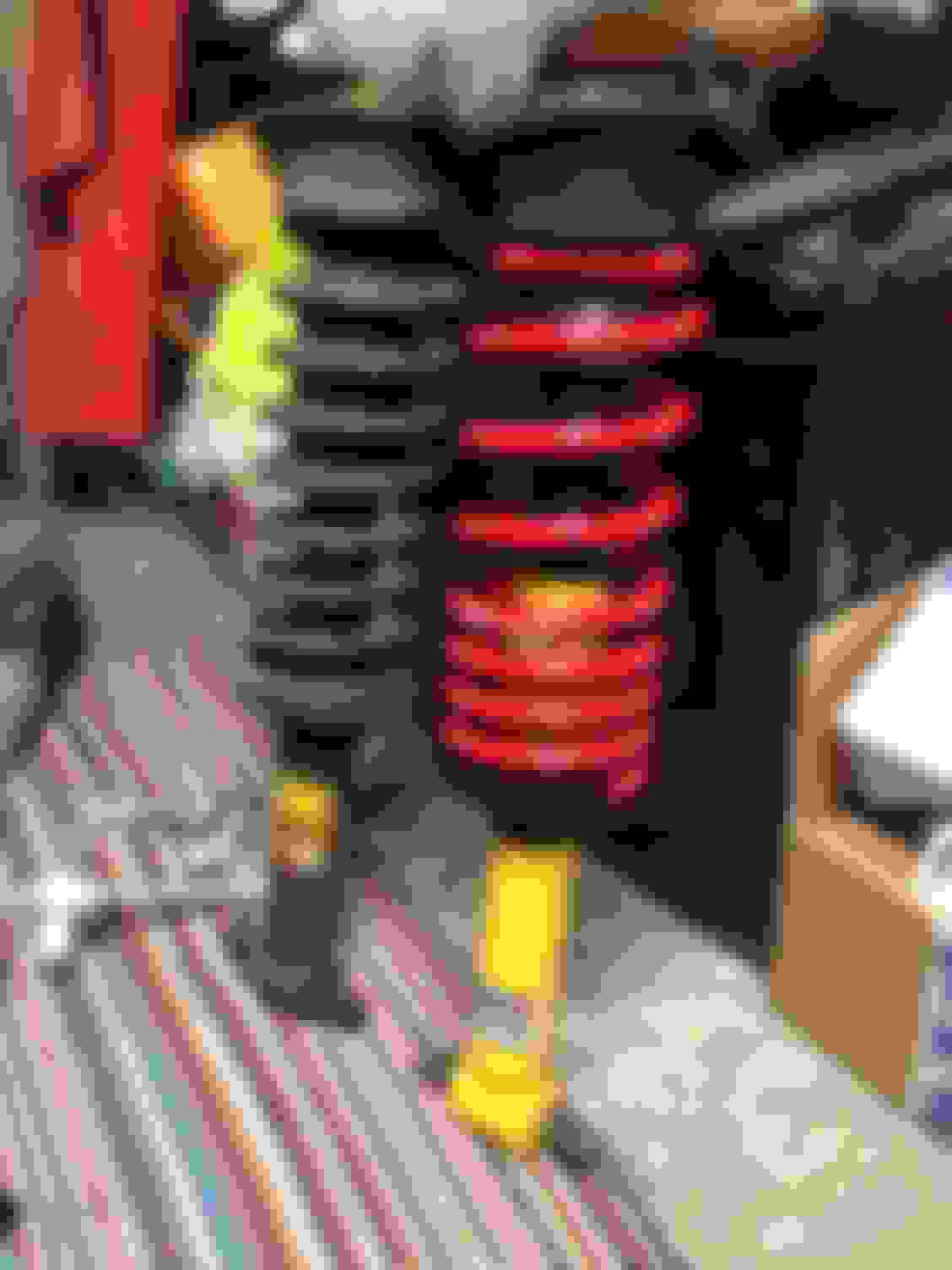
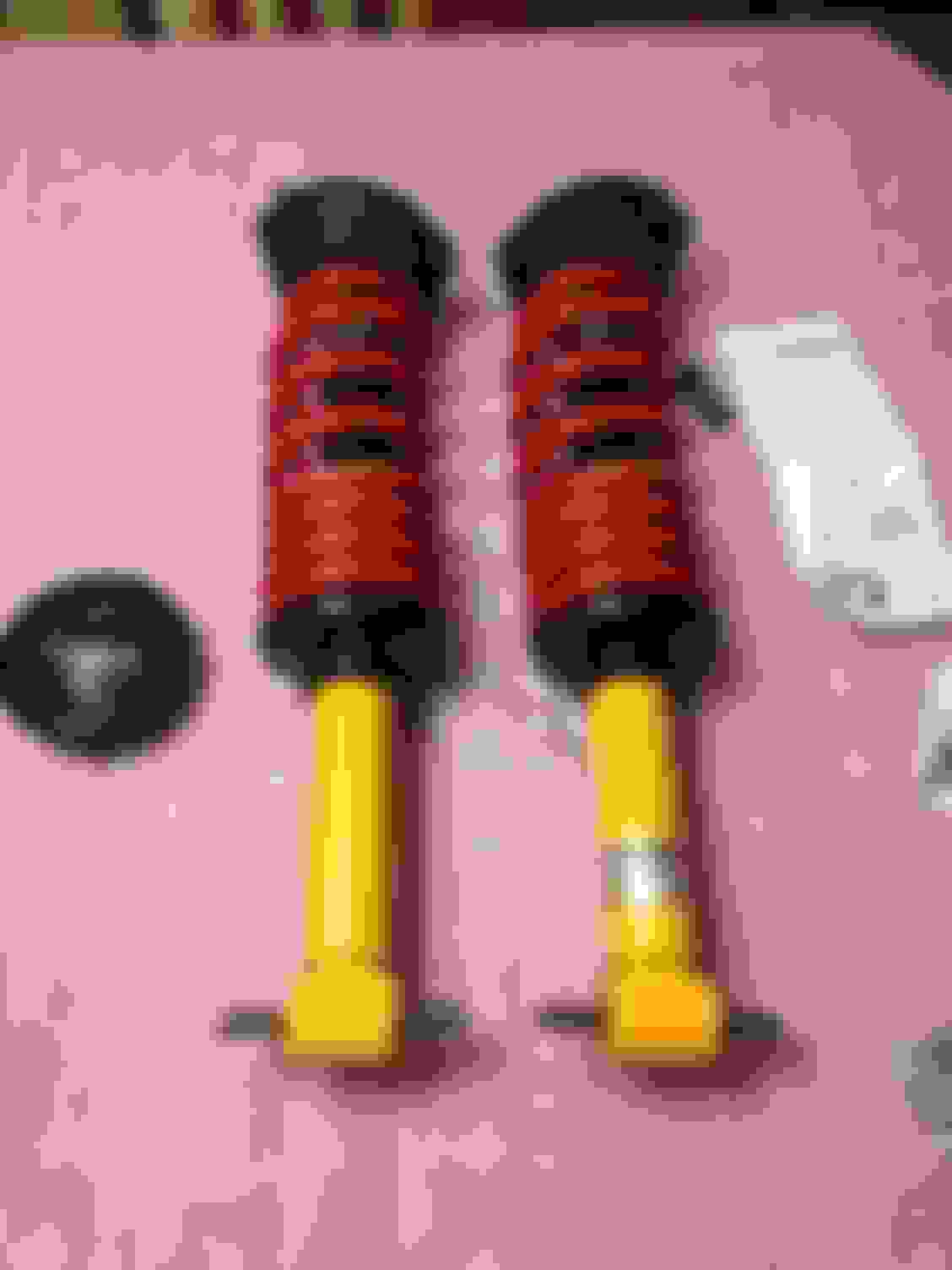
Since I wasn't able to paint today due to the weather, I decided to start putting my springs and shocks together. Here are the parts that will be used.
BMR Lowering Springs - SP090 Koni Single Adjustable Front Shocks - 8241 1139SPORT Moog Strut Mount Assembly, Front Left - K6516
Moog Strut Mount Assembly, Front Right - K6517
Moog Coil Spring Insulator, Front - K6573
Moog Spring Seat, Front Lower - K80927
To avoid having a loaded spring in front of me while documenting, the assembly process is shown without the spring.
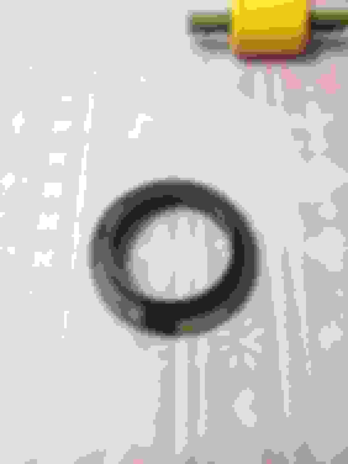
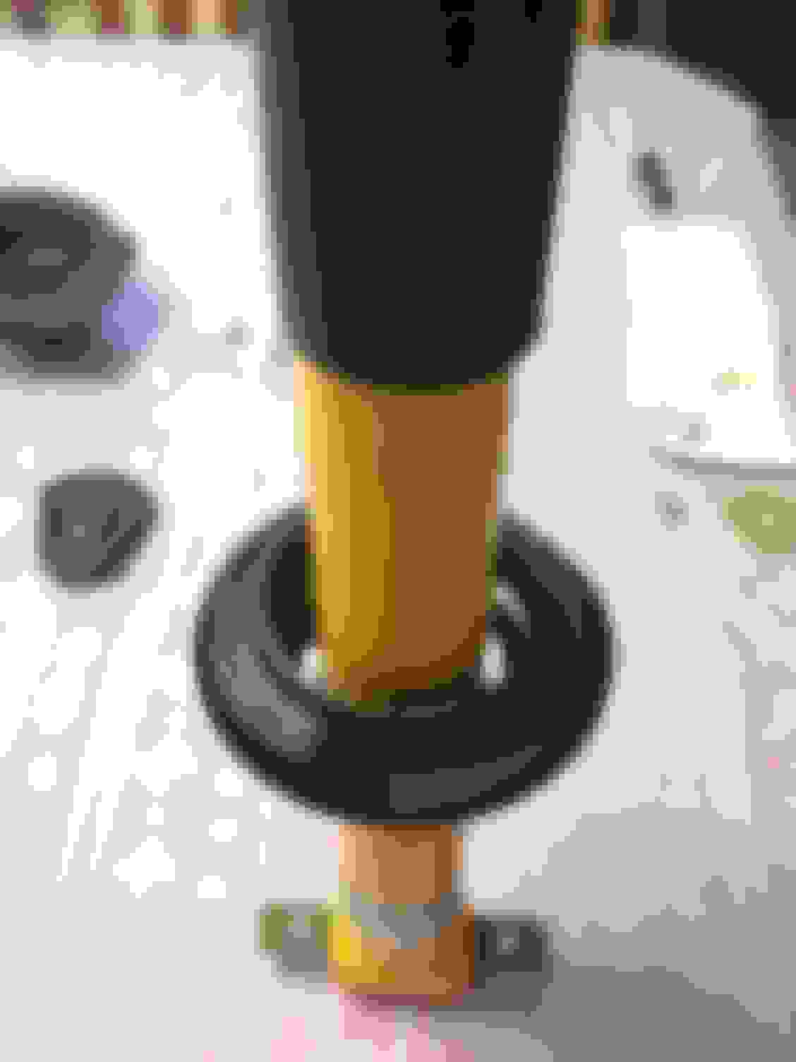
First step, take the Moog spring seat, it comes with a seat and lower insulator. The seat is unnecessary since the Koni's come with the seat already assembled, but the lower insulator is needed. Slide the insulator down and sit it in the Koni seat.
Next, the Koni Sport comes with a large washer, a nut, and a p*** poor set of instructions. Take the washer and sit it on top of the shock.
If the spring was going on, that would be the next part going on. After the spring, the spring mount goes on next on top of the washer. Note that the spring mount is specific to the passenger or driver side.
On top of the mount goes the upper insulator and the nut that comes with the Koni.
One thing to notice is that the Sports do come with a snap ring that hold the lower spring seat. There are two notches for adjusting height. I kept mine on the higher notch.
While actually assembling the shock and spring, it helps to have the original out of the car so you can adjust how the upper mount is positioned relative to the lower shock ears.
Compress the spring so there is some wiggle room between the bottom insulator and upper insulator when fully seated. To tighten the nut on top, use a deep 17mm socket and a pair of channel lock pliers. Carefully grab the adjuster on the shock with the pliers to keep from spinning while tightening the nut.
There is a notch on top of the shock stud that is supposed to be used, but with the upper insulator, it's almost impossible grab the nut with a wrench which is why I used the channel locks by the adjuster.
Before you fully tighten the nut, make sure the adjustment window on the shock is going to be facing toward the outside of the car in relation to the upper mount. Once the nut is tight, if the spring is still loose, the upper mount can be adjusted, however the adjustment window and shock stud will rotate with the mount.
Now, align the upper mount to duplicate it's position in relation to the bottom ears as it is on the original shock. Then adjust the spring to seat properly in the upper mount, and adjust the lower insulator to seat properly with the spring.
Start to decompress the spring, checking regularly the alignment of everything mentioned above as the spring is decompressed. Once the spring is decompressed, you're finished.
Looking good. Funny that I have done, or am doing a lot of the same stuff as you are--or at least very similar.
I have the same Konis, but with Strano springs and antiroll bars. I started with the higher front spring perch as you did, but it was too high in relation to the rear (even with the rear upper isolators still in place), so I went to the lower ones. I have heard some advice against this, but it has been perfect for me for a number of years now.
The only issue with the fronts was some minor squeaking over speed bumps on the driver's side. This was due to rust on the upper mounting plate. I just swapped these and just repainted the underside of the shock towers. (You can see more on this page.)
Lastly, back in 2003, when I bought my 1998, I had to cut off both lower front A-arms, also the rear vertical bolt. That was a pain in the ___. I borrowed a sawzall from one of my dad's friends, since I was staying with him back then, and we bought a pack of the diamond carbide grit blades. I think it took about half a day to get through both of them, with taking breaks to rest my arms from the weight and repetitive stress. I tried sledge hammers and even a ginormous breaker bar to the point that the whole car was rocking on the jack stands. Afterwards I saw why this was an impossible task: the rust had welded the bolt 360 degrees to the inside of the bushing. Luckily, I already had a spare set of A-arms, so I sacrificed the old ones to avoid any wayward cuts into the K-member.
Keep up the good work, your car is going to be a blast to drive when you are all done!
Ah, this reminds me of when I upgraded my front suspension. Great thread. It is so rewarding to knock off rust and then paint the parts. I probably should have done the fender wells like you did though. Did not think of that.
So......would you recommend anti-seize on the A-Arm hardware? How about a crap ton of grease on the upper shock bolt area to try to minimize the rust buildup there as well?
eb110americana, looks good, what did you use to paint your towers?
ws6-speed, I bought the lower control arm set which doesn't include the problem solver bushing, considering my car only sees weather when I get stuck out in it which is rare, and it never sees snow or salt, I think I'll be fine with the old design. I am going to grease up the bolts as well as the upper shock stud and UCA mount to help prevent corrosion as these seem to be the most common rust areas.
Do you have a part number for the problem solver bushing? I was planning on buying the kit but I wasn't aware of a different bushing. What is the difference?
From what I hear, it's just designed in a way to avoid moisture buildup and corrosion in that sleeve which is a common issue on these cars. If my car was a daily out in the elements, I'd definably have it.
I believe the problem solver is K200790 and the OEM style lower kit is K6490 which is what I have. They kind of screw you because I don't think they sell the lower horizontal bushing separately so you basically need to buy both the kit and the problem solver if you're doing all of the lower bushings AND want the problem solver in that vertical position.
You shouldnt need to use a spring compressor to get the new springs mounted. I have the identical springs and shocks, everything went together with no issue. Though I did use the lower mount.
Moog stuff isn't cheap, I spent a pretty penny on everything so far, and I still need to buy tires However, I did do my homework, tubular would have been MUCH more expensive, something I'll eventually do but not now. The other alternative would have been Mevotech which sells factory replacement arms with bushings and ball joints already installed, they're almost the same cost wise as just the Moog bushings and balljoints, which isn't a bad deal considering the time they save you.
I went Moog because I think it's a better product and I plan on road racing, I've heard of guys road racing on Mevotech arms but I felt a little better with Moog and OEM arms. I'm also adventurous, I wanted to do the bushings just to do them. With that being said, I wouldn't do them again, it's a lot of work. Thank god I had clean arms shipped up from Texas because after looking at the arms that came out from under my car which I was originally going to do, those bushings look well rusted in those arms, and pressing the bushings out of the clean arms was hard enough.
If it was a daily or a cruiser, I'd say the Mevotech arms are more than enough for your needs and will save you a lot of time. The only way I'd suggest pressing your own bushings like this is if you have a lot of time and a clean set of arms.
I would put some of that metal/aluminum grease on the threads and shank of the lower suspension hardware to prevent a repeat of the rust issue, yes.
I have Mevotech MK6145T ("Supreme With X Factor Technology") lower ball joints, and it has held up well over 4 years of daily use. The upper one I used a Raybestos 5001087B, which seems to be okay. The rubber bushings are all MOOG. I had a local machine shop press my old ones out/new ones in. The one area I would say that you MUST use "problem-solver" parts on, is the outer tie rods. I am not sure if it is the 1.25" ride height drop or what, but I ate through two sets of O'Reilly ones, and even now, I found one of the MOOG dust boots was torn, so I replaced that.
To paint the upper towers, I ran through the following steps (you can see more pics in the link from my first post):
1) Wash off old grime from fender and grease from top (that grease just dries out and makes a mess, I am not doing that again.)
2) Take a flathead screwdriver or other type of pick to break off all of the loose rust and paint. Don't be afraid to get aggressive.
3) Wire brush by hand to thin out the remaining rust.
4) Rust converter to change surface rust from iron oxide to iron phosphate.
5) Metal etching primer (rattle-can, bought mine in-store at Finishmaster)
6) You can honestly stop at step 5 if you want, as no one will see it anyway, but if you want to paint: AutomotiveTouchUp.com has nearly factory-matching rattle-can base coats. Their clear coats kind of suck though. They look good, but when I painted my license plate cover, after washing the bugs off on a freeway trip, I found that they marred the surface. It just does not dry hard enough. Since it matters less up in the fenders, I did it anyway. Hopefully after some months of drying before the engine goes back in the car, the paint won't stick to the tops of the suspension plates.
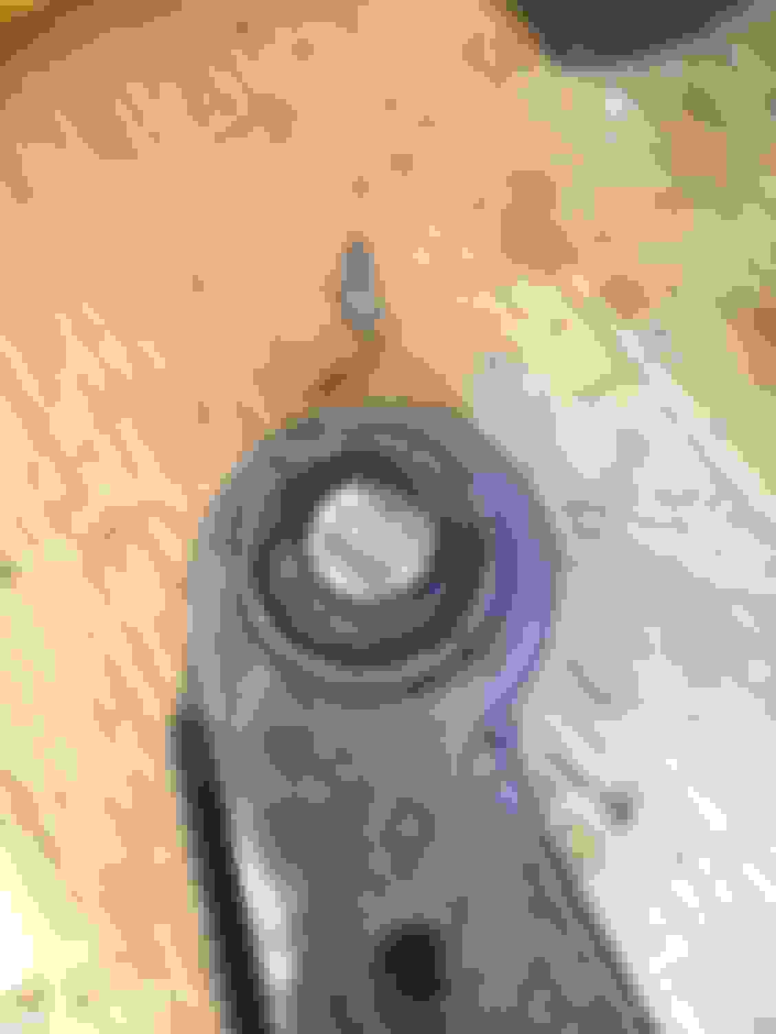
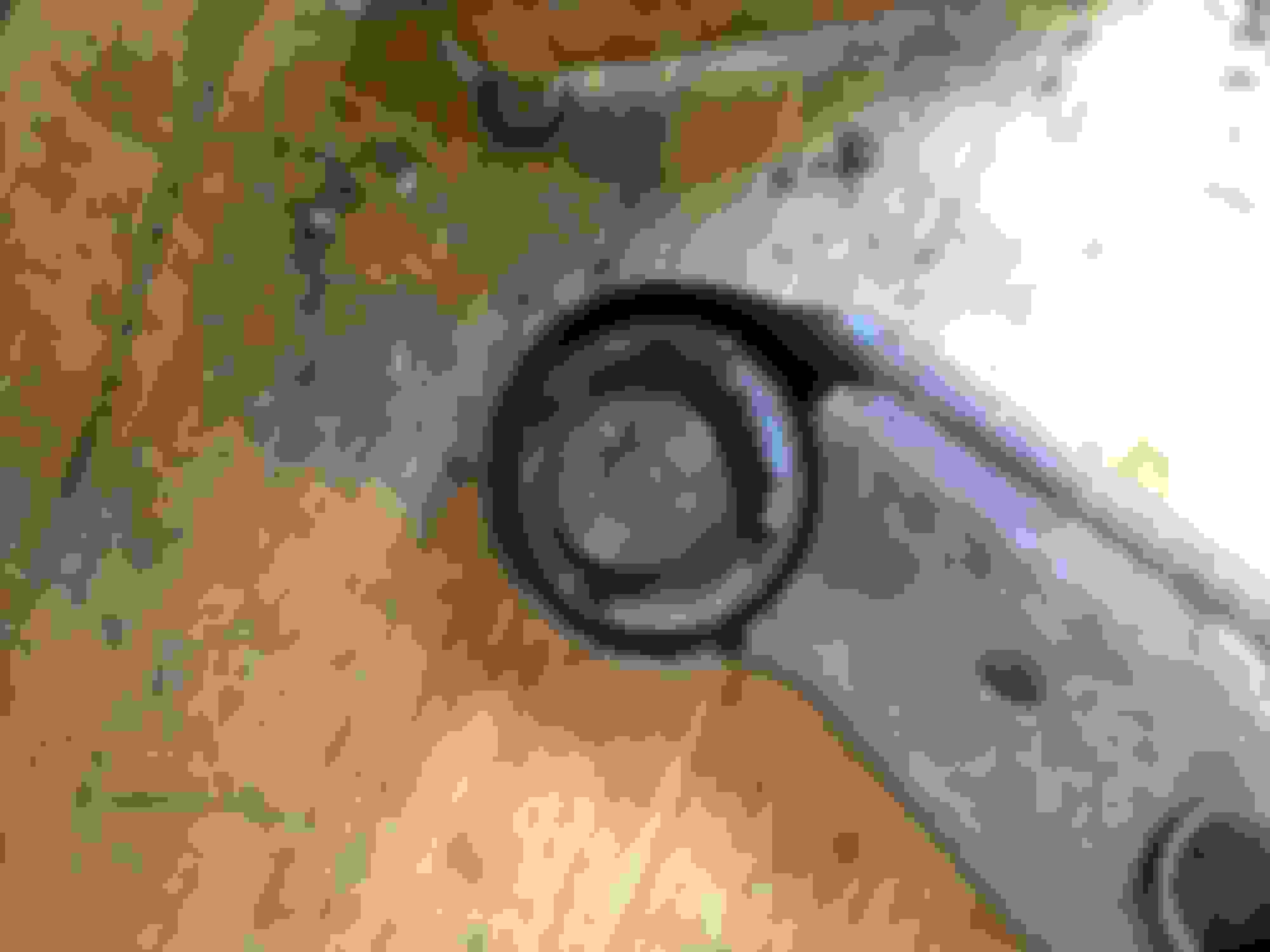
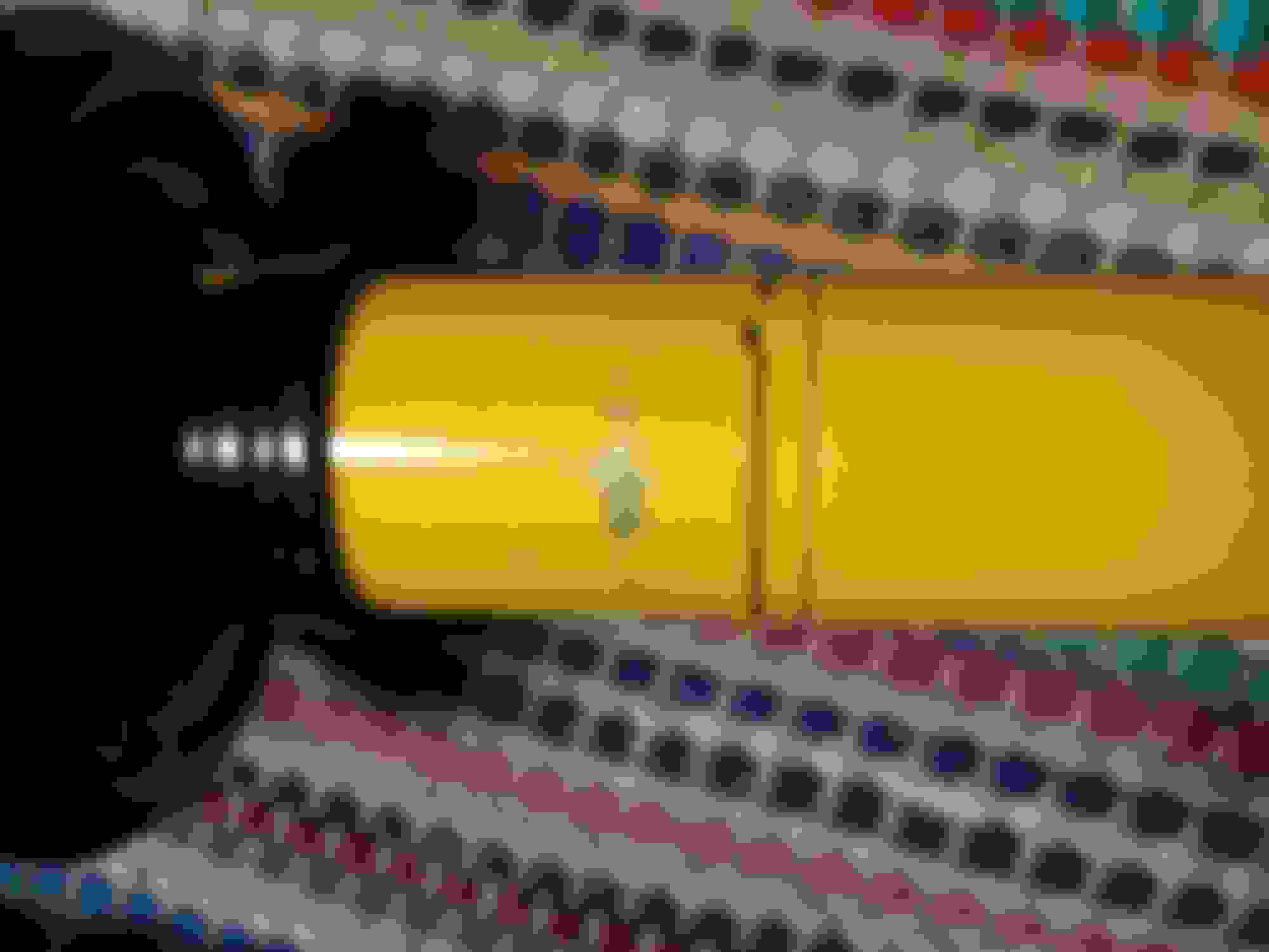
I was using VHT Chassis and Roll Bar Epoxy which came out extremely good on my control arms. However I checked my spindles and upper control arm mounts that I painted last Thursday and there are very tiny orange specs coming through which makes me wonder if that was the right stuff to use on bare/pitted metal, even though it was cleaned up very well and the prep followed as per VHT directions. This is making me second guess using it on the inner fender wells. As far as color goes, I'm going to top coat it with a typical gloss black, my car is black and no ones going to notice if it's not factory match that deep in the wheel well.
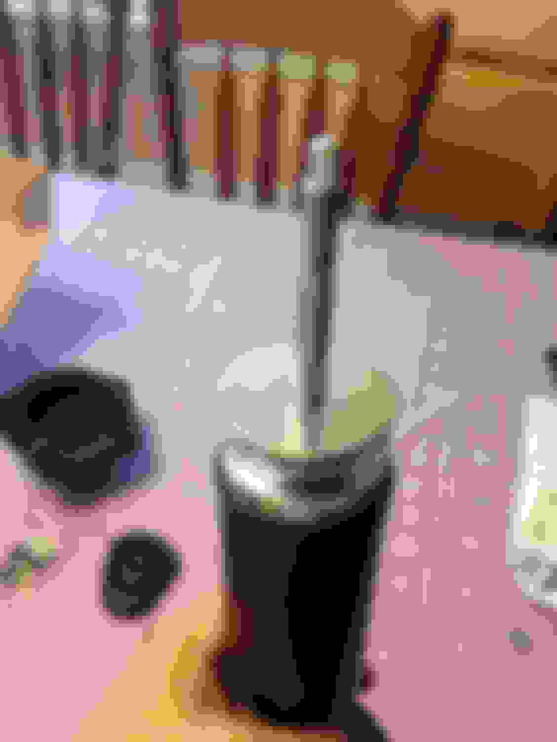
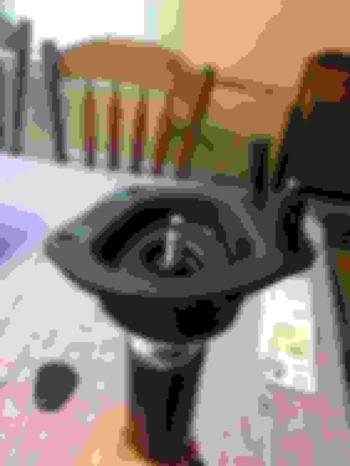
Here are some photos of those specs on my spindles. This is making me worry as it's been four days since they've been painted.
If you use the rust converter (clean off old rust first) and metal etching primer under the epoxy coat, you will be fine. Unless the paint gets scraped all the way through (say, while trying to align the upper shock bolts with their fender holes) it will never rust again.
It is hard to see with your closeup if there is an issue. If so, I guess you just wait for it to "surface" in a few years and then strip them and coat again as I have outlined above. It is probably fine for now. I painted my inner fenders only a couple of weeks ago, so there really isn't anything newsworthy to report. I also painted my rear fender lips a few years back when some paint flaked off after rolling them. They weren't rusted to begin with, but there haven't been any problems there.
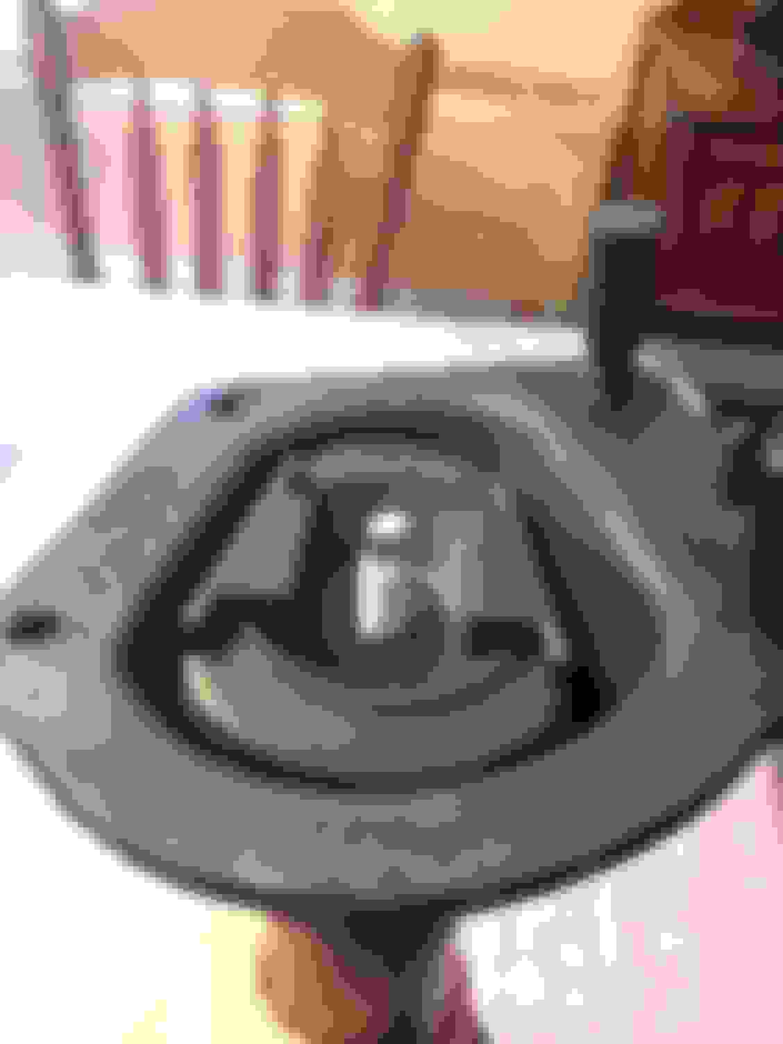
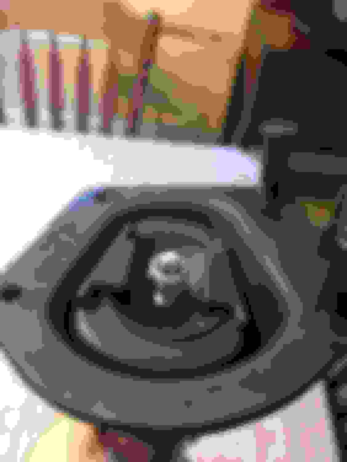
I was talking about it with a good friend of mine who actually witnessed me prep and paint the spindles and upper mounts. He thought my prep was more than enough but thinks I went a little light on the coats and those are just pinholes in the pitting I didn't cover good enough. That would make sense since I did 3 heavy coats on the arms and they came out great, even around the pitting areas, and I remember being a little conservative on the spindles and mounts because I was running low on my last can of paint. Not to mention cast and pitted metal will have a larger surface area to cover than stamped steel.
I going to put on a couple more heavier coats next time the weather breaks and see how they come out. I'm hoping that's it because I really love the finish on my arms with this paint. I was even taping the arms and spindles with a hammer to see if they'll chip or scratch and it seems like a pretty solid coating, especially for a store bought rattle can.
No concerns about clearance in the bolt holes and bushing holes with the extra epoxy on there? I was planning to do POR-15 as I had great results on my 77 vette, but it does add a bit of thickness after the base and top coat.
That was/is a concern. Worst case if it causes issues I'll ream them out real quick, shouldn't be a big deal. I have the bushings in the freezer now, hoping to press them in tonight if I get the time, we'll see how that goes.
 06-03-2017, 10:53 PM


 However, I did do my homework, tubular would have been MUCH more expensive, something I'll eventually do but not now. The other alternative would have been Mevotech which sells factory replacement arms with bushings and ball joints already installed, they're almost the same cost wise as just the Moog bushings and balljoints, which isn't a bad deal considering the time they save you.