
Building Pushrod Front Suspension with Inboard Shocks - could use some advice
 10-06-2008, 11:13 PM
#21
With the amount of travel your trying to get, I would worry about the tube rotating too much where the shock extends and continues to rotate the tube so that the wheels are sucked up way past where you want to go in the wheel wells. Now, I'm sure you've considered this, just wanted to point that out. Also, where are you planning on mounting most of this? Are you going to do a full tube chassis conversion on the front of the car? A lot of the stock points where you "could" mount this design isn't going to hold up to loads the shock towers were designed for. Most of the front was designed to compress in an accident...
Just a few thoughts. Good luck with the design.
Just a few thoughts. Good luck with the design.
I am building a full frame for the car front to rear along with a new floor. The front shock towers will be gone so these rocker assemblies will be next to each exhaust header right on top of the frame rail.
The front suspension is going to be similar to the C4, C5 design using a shorter spindle.
Last edited by JasonWW; 10-06-2008 at 11:21 PM.
 10-07-2008, 04:57 AM
#24
TECH Fanatic

Join Date: Jul 2007
Posts: 1,516
Likes: 0
Received 0 Likes
on
0 Posts
I understand your design idea, and I think it could work if your math and geometry work out right. As far as material, it will depend on what bearings you have available. I would go with roller bearings myself. You should be able to find a machine shop to turn down the ends of the bar stock or tubing you use to match the ID of the bearings.
I dont know what material to recommend for something like this, but if you can figure out the twisting load that will be exerted on the tube, then you then can figure out what material would bet fit the bill. If you go with something too stiff then you have to worry about it snapping.
Ok, now my mind is going a million miles a minute thinking about how to keep this from twisting. I have one Idea, but it would use two separate shafts for each side. Couple these two separate shafts together inside a bearing with a separate piece. If I am correct, this would give you two shorter shafts, which would greatly increase their resistance to twist.
10-07-2008, 06:18 AM
#25
I'm having trouble picturing your idea.
My thought would be similar to a driveshaft with a u-joint bearing on either end. They use roller bearings and are really tough.
As far as diameter goes, larger will make the arms welded to it stronger, but increase the inertia making it harder for it to change directions. How much stregnth is enough? How much inertia or mass is enough to slow down the suspension? I just don't know.
Last edited by JasonWW; 10-07-2008 at 06:26 AM.
10-07-2008, 09:30 AM
#26
TECH Junkie
iTrader: (7)
Join Date: Jul 2005
Location: MA
Posts: 3,934
Likes: 0
Received 0 Likes
on
0 Posts

I probably am more of an engineer than a lot of folks on this board.
Shock side loading isn't any more an issue than they are now in the stock location. No worries there. As long as both ends can pivot freely, your fine.
Yes, I know what are the lowest points, but it doesn't matter to me as I'm building new floors and frame for it.
I can have as much or as little suspension travel as I want. If I use a shock with 3.6" stroke (like stock) and maintain the stock 1.7 motion ratio, I'll have the stock 6" of travel. If I increase or decrease the motion ratio I will be moving the shocks valving out of it's range slightly, but I can always adjust the rebound to compensate some. So unless I switched shocks, I would keep the suspension travel between 5 and 7 inches. This is the front I'm talking about. In the rear I'll have 7"-8" of travel.
Make sense?

That's cool though. I guess as long as you make your own chassis then you only have to worry about what you make.
Now what happened to the drop spindle idea? I thought that was discussed a while ago.
10-07-2008, 10:11 AM
#29
No, flat hood will clear, but TB comes pretty close. If it's too close, I can always add a small, cool looking bulge in the hood. 
I did find out the name of the bearings I need to use in the ends of the shaft. Support bearings are made for this exact type situation. There are lots to choose from.
This one has a 5/8 hole and costs $32.

I did find out the name of the bearings I need to use in the ends of the shaft. Support bearings are made for this exact type situation. There are lots to choose from.
This one has a 5/8 hole and costs $32.
Last edited by JasonWW; 10-07-2008 at 10:21 AM.
10-07-2008, 10:54 AM
#30
I can probably go to a mlitary surplus and get a torsion bar from an old tank or cargo plane (say 40mm-50mm diameter), cut it into a pair of 22" lengths and than have the ends machined down to fit the bearing supports. Those are NOT going to twist. 
I wonder if they can be welded on, though?
I wonder if they can be welded on, though?
10-07-2008, 11:03 AM
#31
I found something close. A pushrod suspension works just like a pushrod in an engine. One one side is the pushrod, then the rocker arm and then the valve (or shock).
Here is a rocker arm from a Harley where the pushrod can't be in line with the valve. It's elongated.
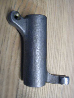
Here is a rocker arm from a Harley where the pushrod can't be in line with the valve. It's elongated.
10-07-2008, 11:51 PM
#34
As neat as this idea is, I may just break down and buy some new shorter shocks at about $500ea. and mount them similar to stock. It just depends on whether I can find out how to build this rocker arm properly. I've had no luck finding a similar design on any vehicle.
10-08-2008, 04:33 AM
#35
Launching!
iTrader: (1)

Join Date: Jun 2002
Location: San Luis Obispo, CA
Posts: 255
Likes: 0
Received 0 Likes
on
0 Posts
it looks like you have a lot of stuff removed in front from the radiator support forward. Could you mount the shock at a 45 angle and put the bottom into the hole where the battery used to be and likewise on the other side (would have to move the fuse boxes). Then you wouldn't have to do a cam, you could use just a rocker right over the current shock towers. This way the shocks mounted at a 45 but angled front (bottom) to back (top).
I'm just confused on where/how you're going to mount the supports for the cam.
I'm just confused on where/how you're going to mount the supports for the cam.
10-08-2008, 05:11 AM
#36
it looks like you have a lot of stuff removed in front from the radiator support forward. Could you mount the shock at a 45 angle and put the bottom into the hole where the battery used to be and likewise on the other side (would have to move the fuse boxes). Then you wouldn't have to do a cam, you could use just a rocker right over the current shock towers. This way the shocks mounted at a 45 but angled front (bottom) to back (top).
I'm just confused on where/how you're going to mount the supports for the cam.
I'm just confused on where/how you're going to mount the supports for the cam.
Wait a minute, are you talking about a rocker on top of the current shock towers? Those towers are going to be removed. There's not going to be room for anything above the tires as they will be almost touching the hood at full drop.
Last edited by JasonWW; 10-08-2008 at 05:16 AM.
10-08-2008, 05:38 AM
#37
TECH Fanatic
Join Date: Jul 2007
Posts: 1,516
Likes: 0
Received 0 Likes
on
0 Posts
well, I dont understand this equation too much, but i found it on the net. It is the equation to find the torsional stiffness of round bar. Dont ask me how to use it, but I thought if you could figure it out it will help in your design.
Here is the equation:
k=GJ/L
k=spring rate of the bar
L=length of the bar
G=Modulus of Rigidity of the material
J=polar 2nd moment of inertia (depends on the material shape)
in the case of a solid round bar, J=(pi*d^4)/32
Therefore k=(G*pi*d^4)/(32*L)
Here is the equation:
k=GJ/L
k=spring rate of the bar
L=length of the bar
G=Modulus of Rigidity of the material
J=polar 2nd moment of inertia (depends on the material shape)
in the case of a solid round bar, J=(pi*d^4)/32
Therefore k=(G*pi*d^4)/(32*L)
10-08-2008, 08:44 AM
#38
TECH Fanatic
iTrader: (4)
Join Date: Dec 2003
Location: Phila, Pennsyltucky
Posts: 1,520
Likes: 0
Received 0 Likes
on
0 Posts

I actually have a camaro and a vette. ;-)
take a look a how these shocks are horizontal and you could fit the motor between them.
http://www.customtacos.com/forum/showthread.php?t=60088
take a look a how these shocks are horizontal and you could fit the motor between them.
http://www.customtacos.com/forum/showthread.php?t=60088
10-08-2008, 10:54 AM
#39
Have you ever looked under the hood?
There's no room on top of either engine. Besides, I'm raising my engine around 2" higher than stock and it's going to be a tight fit as it. Plus keep in mind, the Koni 4th gen shocks can't be mounted at more than a 45* angle. So I have to work within those limitations. Unless, I switch to a different shock.
On that truck website, I'm not even sure that IS a cantilever shock setup. It looks like a rocker arm to me since the pivot is in the middle. If that was a indepentant suspension and not a solid axle, it would never work.
I forgot to search under "cantilever suspension". That gives me something to do tonight.
10-08-2008, 12:00 PM
#40
TECH Fanatic
iTrader: (4)
Join Date: Dec 2003
Location: Phila, Pennsyltucky
Posts: 1,520
Likes: 0
Received 0 Likes
on
0 Posts
Have you ever looked under the hood?
There's no room on top of either engine. Besides, I'm raising my engine around 2" higher than stock and it's going to be a tight fit as it. Plus keep in mind, the Koni 4th gen shocks can't be mounted at more than a 45* angle. So I have to work within those limitations. Unless, I switch to a different shock.
On that truck website, I'm not even sure that IS a cantilever shock setup. It looks like a rocker arm to me since the pivot is in the middle. If that was a indepentant suspension and not a solid axle, it would never work.
I forgot to search under "cantilever suspension". That gives me something to do tonight.
There's no room on top of either engine. Besides, I'm raising my engine around 2" higher than stock and it's going to be a tight fit as it. Plus keep in mind, the Koni 4th gen shocks can't be mounted at more than a 45* angle. So I have to work within those limitations. Unless, I switch to a different shock.
On that truck website, I'm not even sure that IS a cantilever shock setup. It looks like a rocker arm to me since the pivot is in the middle. If that was a indepentant suspension and not a solid axle, it would never work.
I forgot to search under "cantilever suspension". That gives me something to do tonight.