


What to do with factory external voltage reg and alt wiring for 06' LS2 in 69' Camaro
I am installing a 06' LS-2 from a GTO in a 69 Camaro and having John from Speartech do the wiring harness modifications. Question: What happens with the stock wiring to the factory external voltage regulator and the original alt wiring? I would still like to use the factory amp gauge/gen light in the car(if possible). Also, where does the stock fuse panel get it's power from? The stock resistor wiring is still in place for powering the external coil also?
This may all be answered when I get my harness back, but was just trying to clean-up the engine compartment b-4 I do my last test fit.
Thanks
This may all be answered when I get my harness back, but was just trying to clean-up the engine compartment b-4 I do my last test fit.
Thanks
Your LS2 alt should have a built-in regulator. This means that you'll no longer require the use of the stock reg. I can't remember exactly what I did with the old reg wiring. If the wiring went directly from the old alt, to the batt, you can remove it. However, if the old reg wiring was bridged to the +12v supply and the harness which travels eventually to your fuse block, you must bridge it/retain it. In addition, you will run a heavier gauge wire from the + of your batt, to the lug on your alternator. 8 GA should satisfy the ALT to BATT requirement. Here is a wire gauge chart for future reference. Your old alt produced less power (about 75-80 amps) than your new alt. I think that the NEW ALTS PRODUCE 125 AMPS or so. Please verify this.
I assume that bec you have a factory amp gauge, that the wiring for this gauge still exists? If so, remember that the new alt potentially can deliver MORE AMPERAGE than the old regulator! Because the AMP GAUGE WIRING can carry the full load of battery into the cabin, please make sure that the wire is the PROPER GAUGE, or a fire might ensue. Also, is the old gauge capable of handling the requirement of the the new alternator?
The fuse panel is powered by wiring begin @ the batt, then travels around the front/behind the radiator, then under the driver's fender, to the fuse block.
Because you now have 8 separate coils (rather than one for the old setup), there are no more resistors/ballasts, etc. Your new harness will have the appropriate wiring for each coil.
John is very helpful at answering any questions you have.

Last edited by gMAG; Feb 13, 2011 at 01:14 AM.
I had a similar set up on a Datsun. The external voltage regulator goes bye bye. You really shouldn't have to do anything to retain your amp meter.
Not sure how a Camaro is wired, but the amp meter typically doesn't measure the current coming out of the alternator. On most cars it only measures the amps going into the battery circuit.
A bigger question you may want to ask is whether you should keep the amp meter or upgrade to a voltmeter. On my Datsun it was as simple as grabbing a voltmeter out of a later year Z and changing some wiring. There is a reason cars no longer run amp meters, battery current has to loop through the dash harness to be plumbed through the meter. This is what the main power lug looked like on my 35 year old Datsun

The link below gives a pretty good if long winded discussion of amp vs. volt meters
http://www.madelectrical.com/electri...witworks.shtml
Not sure how a Camaro is wired, but the amp meter typically doesn't measure the current coming out of the alternator. On most cars it only measures the amps going into the battery circuit.
A bigger question you may want to ask is whether you should keep the amp meter or upgrade to a voltmeter. On my Datsun it was as simple as grabbing a voltmeter out of a later year Z and changing some wiring. There is a reason cars no longer run amp meters, battery current has to loop through the dash harness to be plumbed through the meter. This is what the main power lug looked like on my 35 year old Datsun
The link below gives a pretty good if long winded discussion of amp vs. volt meters
http://www.madelectrical.com/electri...witworks.shtml
Just do away with the Camaro setup. Use the LS setup, The alternator should be controlled by the PCM and Engine wiring harness. You can either wire the Alternator output directly to the battery or to the Camaro under hood system (horn Relay). That is what I did for my Chevelle and going to do for my Nova.
So I will not need any of the wires from the original harnesses to provide for the ECM? Don't some of the wires to the regulator tie in to the horn relay which is next to the regulator and can't be eliminated? Will the purple crank wire from the ignition switch hook to the ECM or does it still go directly to the starter? I guess I am a little confused..... How will the fuse box get it's power?
So I will not need any of the wires from the original harnesses to provide for the ECM? Don't some of the wires to the regulator tie in to the horn relay which is next to the regulator and can't be eliminated? Will the purple crank wire from the ignition switch hook to the ECM or does it still go directly to the starter? I guess I am a little confused..... How will the fuse box get it's power?
The photo posted is the reason why the gauge of wire used on amp meters needs to be on the large side. Older cars & their accompanying electrical requirements were a fraction of the requirements of today's car's (even though you'll still be driving an 'older' car). Stereo systems, air, electronic ignitions and the like are the reasons why the newer alternator has a larger output. In other words, in the photo, even with yesterday's elec requirements, there are burned wires.
I did what Pop n Wood suggested & replaced my amp meter with a voltmeter.
To answer your above question...remove the regulator & its' wiring from the old alternator-you won't need it.
John @ Speartech will send you the harness which will have a PURPLE wire which will be attached to your starter solenoid. Route this wire through your firewall, then to the ignition switch. Presently, on your ignition switch is a purple wire. Cut the purple wire presently on the switch & connect it to the Speartech purple wire.
When you receive the harness, the directions will give you an option, which is that you can just retain your present purple wire, which goes from solenoid to ignition switch. Your choice.
The fuse box will get its' power from the existing (old) harness (large RED wire) coming from under the driver's fender. As I mentioned above, if you follow the RED feed wire from the battery, it should now run along the front/radiator, feed the horn relay, then make its' way to the driver's fender, then to the fuse box.
Sent you a PM!
Last edited by gMAG; Feb 13, 2011 at 11:01 PM.
Trending Topics
GM used a shunt style Amp gauge. I am trying to remember off the top of my head but I do know that all the power of the car does not run through the original gauge. The little brown wire coming off the gauge goes to the dash light and provides resistance to excite the regultor on a internally regulated alternator (I have converted several Chevelles to a SI style alternator and used this wire).
Below is something I copied and pasted about the Chevelle ammeter but GM pretty much did things the same across the board.
No current does not flow from alt through the meter in a 70. I believe they call it a shunt type meter. It's actually a millivolt meter connected as mentioned. It's measuring the voltage drop between the horn relay and junction block. Depending on direction of current flow, charge or discharge, and the amount of current which affects the voltage drop the meter shows it as amps. It's just a matter of knowing the wire size and length to calculate voltage drop based on current then using a meter calibrated to display the current flow, amps, based on the voltage drop.
__________________
http://www.chevelles.com/forums/showthread.php?t=191692
LS1 Tech Stories
The Best V8 Stories One Small Block at Time

Topdon ONE vs. Artidiag 800 BT2: Which is the Diagnostic Tablet For You?
Pouria Savadkouei
Gas Monkey Built a 6-Wheel Ferrari Testarossa With a Corvette LT4 Engine
Verdad Gallardo
7 Most Reliable High-Performance Engines GM Has Ever Built
Verdad Gallardo
Amazing '71 Camaro Restomod Is Modern Muscle Car Under the Skin
Verdad Gallardo
6 Common C5 Corvette Failures and What's Involved In Repairing Them
Pouria Savadkouei
Retro Modern Bandit Pontiac Trans AM Comes With Burt Reynolds' Autograph
Verdad Gallardo
Top 10 Greatest Cadillac V Series Performance Models Ever, Ranked
Pouria Savadkouei
Top 10 Most Powerful Chevy Trucks Ever Made!

Hennessey's New Supercharged Silverado ZR2 Has 700 HP
Verdad Gallardo^^^gMAG... Not entirely correct. Not trying to pick a fight here so bear with me. I recently got my harness from John (New harness). There is NO purple wire that connects to the starter. There is a PINK wire that attaches to the starter switch. The purple wire is from the stock harness and connects to the starter solenoid like before. I need to figure out the alternator also. Johns' harness has a connection for the alternator but its the wrong connector. So I need to figure out which one goes where.
It would have been nice to have the pass through purple wire which would clean up the engine compartment even more but I will have to use my original harness.
It would have been nice to have the pass through purple wire which would clean up the engine compartment even more but I will have to use my original harness.
I'm looking @ my sheet, and it specifically reads as posted above. I did use the purple wire supplied by John @ SPEARTECH, rather than the existing one on the car. It runs from the starter soleniod to the ign. Just verified the wiring on my car, too.
At the least John @ SPEARTECH is getting quite a few plugs here! lol
Bowtie, My mistake...I agree with you. My orig ammeter had the setup you've described. I was going to go with the AutoGage amm, which is not the same as the OEM, though. I changed my mind and went to their voltmeter, instead.
I still think that Pop n Wood's pic speaks for itself. Sorry for misleading, everyone!
I still think that Pop n Wood's pic speaks for itself. Sorry for misleading, everyone!
GM used a shunt style Amp gauge. I am trying to remember off the top of my head but I do know that all the power of the car does not run through the original gauge. The little brown wire coming off the gauge goes to the dash light and provides resistance to excite the regultor on a internally regulated alternator (I have converted several Chevelles to a SI style alternator and used this wire).
Below is something I copied and pasted about the Chevelle ammeter but GM pretty much did things the same across the board.
No current does not flow from alt through the meter in a 70. I believe they call it a shunt type meter. It's actually a millivolt meter connected as mentioned. It's measuring the voltage drop between the horn relay and junction block. Depending on direction of current flow, charge or discharge, and the amount of current which affects the voltage drop the meter shows it as amps. It's just a matter of knowing the wire size and length to calculate voltage drop based on current then using a meter calibrated to display the current flow, amps, based on the voltage drop.
__________________
http://www.chevelles.com/forums/showthread.php?t=191692
Below is something I copied and pasted about the Chevelle ammeter but GM pretty much did things the same across the board.
No current does not flow from alt through the meter in a 70. I believe they call it a shunt type meter. It's actually a millivolt meter connected as mentioned. It's measuring the voltage drop between the horn relay and junction block. Depending on direction of current flow, charge or discharge, and the amount of current which affects the voltage drop the meter shows it as amps. It's just a matter of knowing the wire size and length to calculate voltage drop based on current then using a meter calibrated to display the current flow, amps, based on the voltage drop.
__________________
http://www.chevelles.com/forums/showthread.php?t=191692
It looks like American Autowire makes a factory looking voltmeter for the center console of the 68-69 Camaros and Novas. $119
That looks to be a better way of keeping the factory look. I don't need any melting of wires or fires in the car. Not many people will know the difference. Will the in dash factory GEN light be stuck on all the time?
It looks like the factory resistor wires for the ignition coils can go and just replace the wire with std wire for the pink swithced 12volt wire to ECM.
You're going to hate me, but I looked up a wiring diagram for a 69 camaro. It is completely different than what was used in my Datsun.
Your camaro doesn't use a true ammeter but rather a voltmeter that measures the voltage drop along the wire from your horn relay to the junction box at the back of the battery. So Bowtie70SS got it right. The power doesn't run through the dash.
I was correct when I said the ammeter only measures the current flowing into or out of the battery. In that sense the alternator rating won't affect the meter.
I would still consider replacing the ammeter with a voltmeter just because they tell you more. Get a corroded connection and that ammeter is going to be far from accurate. It is basically relying on the resistance of that wire to be a certain value to be accurate.
No prob, just trying to help out. I always wondered why all the power did not need to flow through the instrument cluster and how it could have worked through the flimsy printed circuit on the back.
I never understood why anybody made ammeter for cars. A voltmeter is perfectly appropriate, and seemingly less complicated. It also gives a great indication of whether your alternator is getting current or not.


KWKrat2, do you have a Gen light (in dash) or do you have a factory style AMP gauge (in the console)? Are you using the original style wiring factory harness? The speartech harness (for the engine) doesn't replace your body harness. Its just for the engine conversion. If you are using the factory harness with the new style alternator, its pretty easy to convert. Check out this link- http://www.camaros.net/techref/ftecref14.html Mainly for the old external regulator.
You have 2 options for doing this:
1-You can either cut your old regulator wires and route them like in the picture and go to your local auto parts store and buy a new pigtail for the alternator. Splice the new alt pigtail into you factory harness (there are two wires- blue/white) http://novaresource.org/alt/12sialt.jpg
2- Buy a kit like this- http://www.americanautowire.com/cata...ersionKits.pdf and the conversion is plug and play. AAW has great customer service and will be able to help you either way (whether you have alight or a gauge).
I have both. The wiring harness in the car is all completely original. I have the battery harness from the GTO which has the battery cables, ground wires and a wire that goes to the starter, but the I believe the LS-2 harness has the wiring for the alt in it. If that's the case, I shouldn't need any of the original wiring for the alt or need to convert it over.
TECH Enthusiast
Joined: Jan 2010
Posts: 578
Likes: 4
From: REALITY
KWKrat2, do you have a Gen light (in dash) or do you have a factory style AMP gauge (in the console)? Are you using the original style wiring factory harness? The speartech harness (for the engine) doesn't replace your body harness. Its just for the engine conversion. If you are using the factory harness with the new style alternator, its pretty easy to convert. Check out this link- http://www.camaros.net/techref/ftecref14.html Mainly for the old external regulator.
You have 2 options for doing this:
1-You can either cut your old regulator wires and route them like in the picture and go to your local auto parts store and buy a new pigtail for the alternator. Splice the new alt pigtail into you factory harness (there are two wires- blue/white) http://novaresource.org/alt/12sialt.jpg
2- Buy a kit like this- http://www.americanautowire.com/cata...ersionKits.pdf and the conversion is plug and play. AAW has great customer service and will be able to help you either way (whether you have alight or a gauge).
You have 2 options for doing this:
1-You can either cut your old regulator wires and route them like in the picture and go to your local auto parts store and buy a new pigtail for the alternator. Splice the new alt pigtail into you factory harness (there are two wires- blue/white) http://novaresource.org/alt/12sialt.jpg
2- Buy a kit like this- http://www.americanautowire.com/cata...ersionKits.pdf and the conversion is plug and play. AAW has great customer service and will be able to help you either way (whether you have alight or a gauge).
B+ lead: wire going to the battery(voltage sensoring done here)
L lead(pin C2 56 orange wire): leads to the 3k ohm resistor (50mA max ) and is the generator turn on signal from the ECM. This wire goes to the ECM.
F lead(pin C2 45 gray wire): this is the generator field duty cycle signal. This wire goes to the ECM.
Ground connection (via the installation bolts)
diagram below is for an 05-06 GTO charging system generator/aka alternator
below is my setup in a 69 Chevelle with an 06 LS2 out of an 06 GTO
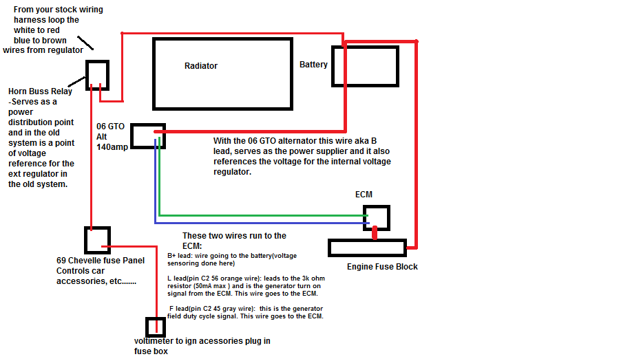
Hopes this helps the OP understand...... Also another tip: buy a new horn relay if you use this system.... My orginal one was rusted and corroded and was causing incorrect voltage readings and drops... I replaced it and bout it from Oreilly's $12.... not voltage issues..... 13.8-14.0......13.4-13.5 with the lights on.
Bozz
Last edited by bozzhawg; Feb 15, 2011 at 01:28 PM.