
Headlight switch led
 03-09-2011, 11:03 AM
#1
TECH Enthusiast
Thread Starter
iTrader: (25)
Join Date: May 2009
Location: NY
Posts: 523
Likes: 0
Received 0 Likes
on
0 Posts

If I solder a 3mm led in the headlight switch, do I need to attach a resistor? I tried touching the led leads to the switch contacts(without a resistor), just to see if it would work, and I guess that was a bad idea since the led blew up and burnt out when it made contact.
 03-09-2011, 12:40 PM
#4
TECH Enthusiast
Thread Starter
iTrader: (25)
Join Date: May 2009
Location: NY
Posts: 523
Likes: 0
Received 0 Likes
on
0 Posts
Also, when dealing with leds, how do you know when you need a resistor and when you don't? I swapped to blue leds in the odometer and didn't need resistors, but I guess they were in the board already, right?
03-09-2011, 01:06 PM
#5
On The Tree
iTrader: (1)

Join Date: Jan 2011
Location: levittown, pa
Posts: 177
Likes: 0
Received 0 Likes
on
0 Posts
You know when based on what voltage the LED happened to be. They're all definitely not 12V led's since 12v LED's dont really exist. usually the voltage is less than half that. So you get a resistor (depending on current draw too) that will drop the voltage to what the LED wants.
R = V/I (where R is the resistance you need and V is the difference in voltage of 12 and LED nominal voltage and I is current that the LED uses)
Lets take a white 3mm LED from superled's.
it has a nominal voltage of 3.4V.
it has a continuous current draw of 25mA.
so, the resistor we need can be any tiny resistor, since the current wont cause much heat (1/4 watt should work fine)
Now the value it must have is defined by (12-3.4)/ .025
or 344 Ohms
It's normal to put it on the positive side,but it really doesn't matter.
EDIT: Also, give yourself room for charging voltage (driving voltage is usually around 14 or so) if you use nominal values for the LED, you should be fine. Dont use max specs when determining the resistor unless you're using max voltage (maybe 15 would be safe there). or you could damage the LED.
Last edited by safemode; 03-09-2011 at 01:21 PM.
03-09-2011, 01:12 PM
#6
It doesn't matter which side of the LED you solder the resistor to...it will work the same either way.
As for when you need one vs. when you don't, it depends on the characteristics of the LED itself. The reason why I'm guessing you burned out the LED you tried to use is because it was rated for 3.3V, and you applied 12V - that's why you need the resistor for that one. The bulbs you ordered as replacements for your gauge cluster were already rated for 12V input voltage, meaning they were already configured to accept that without the need for additional resistors (this is typical for LEDs that are drop-in replacements for standard incandescent bulbs).
As for when you need one vs. when you don't, it depends on the characteristics of the LED itself. The reason why I'm guessing you burned out the LED you tried to use is because it was rated for 3.3V, and you applied 12V - that's why you need the resistor for that one. The bulbs you ordered as replacements for your gauge cluster were already rated for 12V input voltage, meaning they were already configured to accept that without the need for additional resistors (this is typical for LEDs that are drop-in replacements for standard incandescent bulbs).
Trending Topics
03-09-2011, 04:36 PM
#9
I've got an '01 Camaro, and all we need to do is swap a bulb. Is this not the case for you T/A guys?
Here are some of my pics from the bulb install.
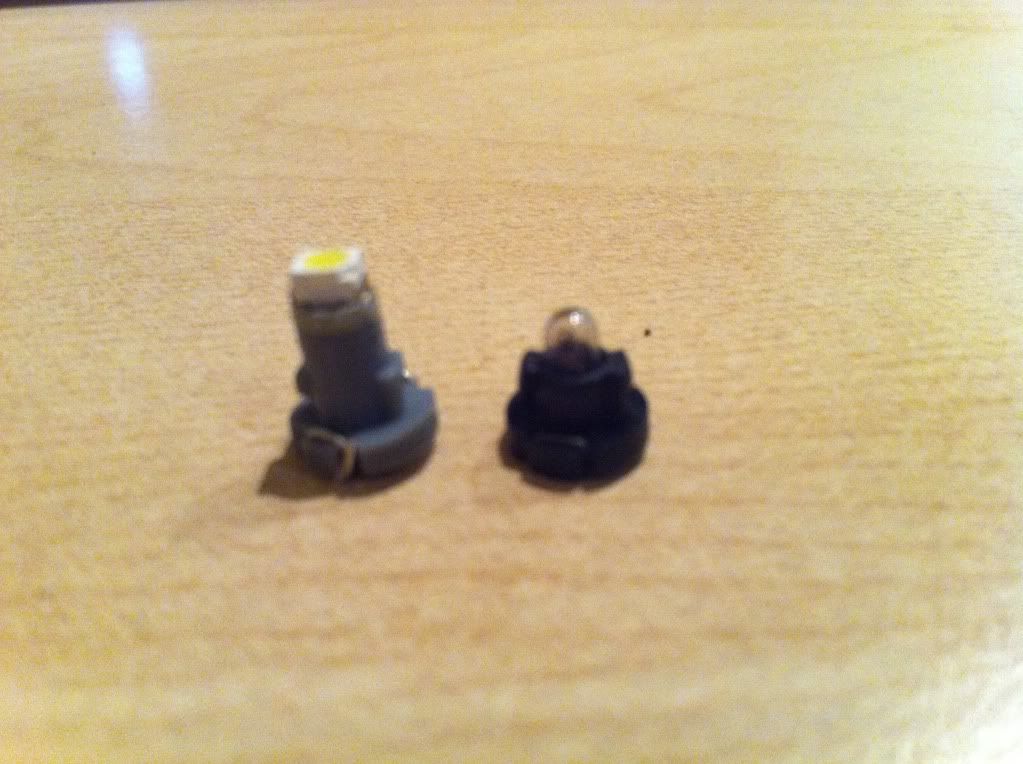
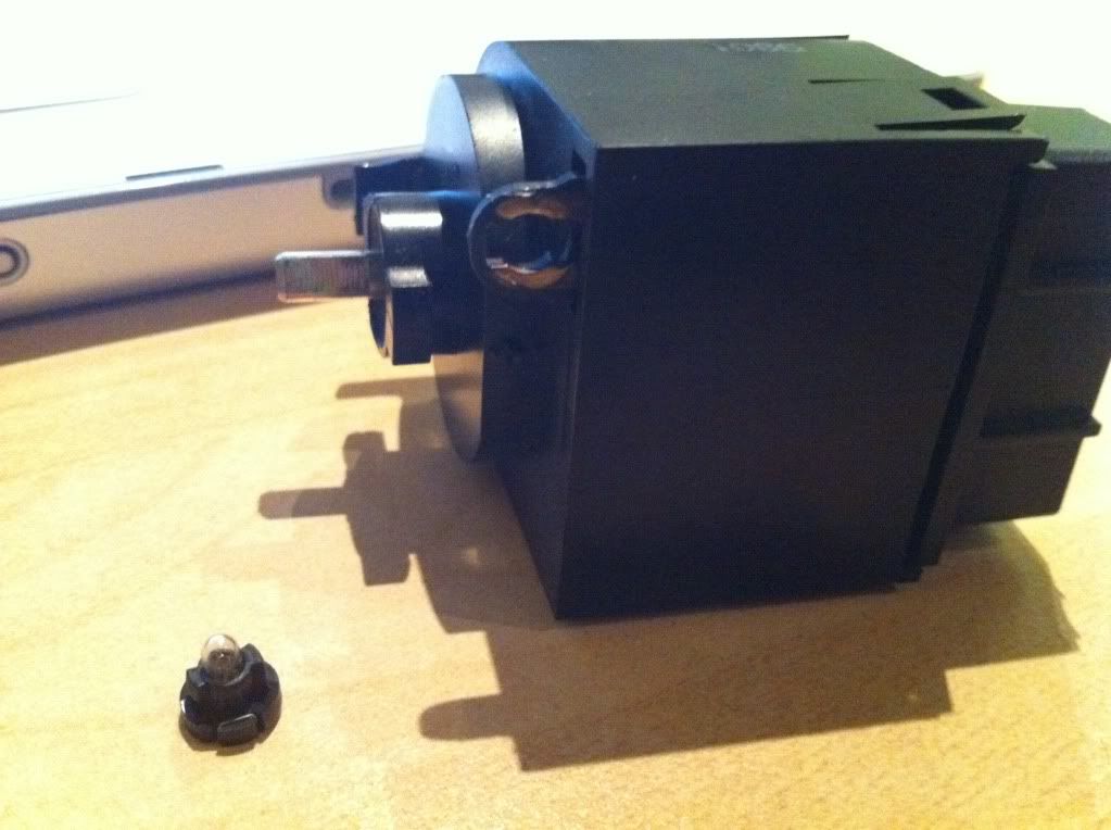
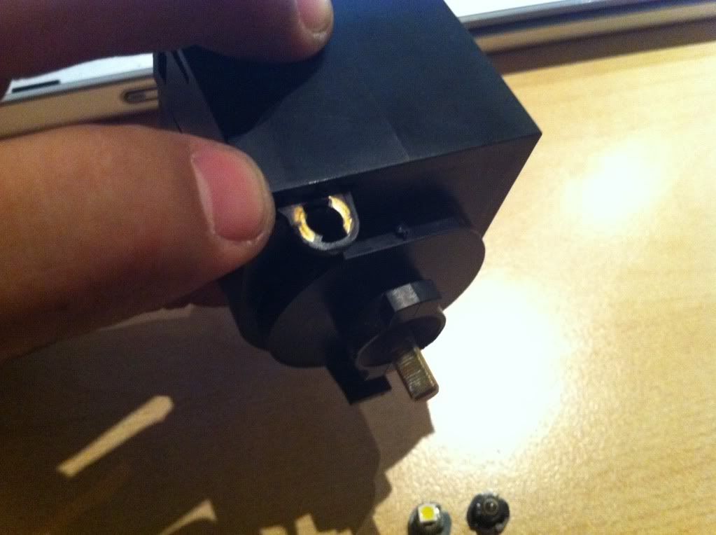
Here you can see the grey bulb installed. It took maybe 6-7 minutes to tear it all apart, install the bulb and rebuild it. Tuns out it doesn't need to be torn apart, lol. It's a 1 minute job.... just pop the bulb out, insert the LED and DONE!
Here are some of my pics from the bulb install.
Here you can see the grey bulb installed. It took maybe 6-7 minutes to tear it all apart, install the bulb and rebuild it. Tuns out it doesn't need to be torn apart, lol. It's a 1 minute job.... just pop the bulb out, insert the LED and DONE!
03-09-2011, 04:53 PM
#10
11 Second Club
iTrader: (8)

Join Date: Jul 2005
Location: NW IN
Posts: 1,730
Likes: 0
Received 0 Likes
on
0 Posts
You're not the only one Sommer86, I took mine all the way apart and then realized I was doing more work than I had too.
I've always wondered why the TA's had to do more work to replace theirs as well.
I've always wondered why the TA's had to do more work to replace theirs as well.
03-09-2011, 06:34 PM
#11
What I've found is that replacement is NOT a good solution to this problem...you are replacing a 360* light pattern with one that is very directional. While that is not a huge issue with most of the interior lights, it is with this one...if you don't get uniform light dispersion, the waveguide (the clear plastic piece) can't do its job, and you'll end up with hot spots and areas that also have no light. They actually make LEDs with phosphorescent coatings that have 360* beam patterns instead of the 30-60* pattern that is more common with LEDs, and is really what should be used in this application (not the surface mount LED shown above).
The problem in this case is you are working around a design that was done when incandescent lighting was the only option, hence the waveguides being the way they are.
The problem in this case is you are working around a design that was done when incandescent lighting was the only option, hence the waveguides being the way they are.
03-09-2011, 08:08 PM
#12
TECH Enthusiast
Thread Starter
iTrader: (25)
Join Date: May 2009
Location: NY
Posts: 523
Likes: 0
Received 0 Likes
on
0 Posts
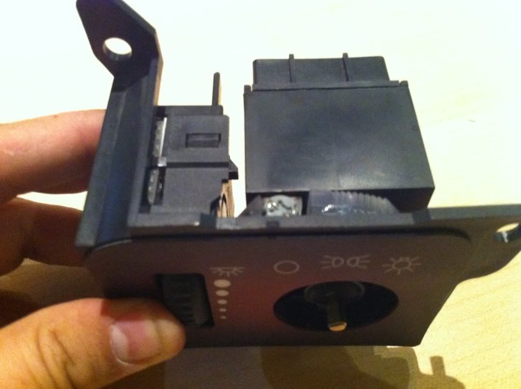
The TA switch is pretty much the same. I actually have a TA switch assembly with a camaro ****, dimmer and overlay. I bought one of those bulbs from superbrightleds but it wouldn't fit properly and I lost it when I was trying to trim it down a bit. So I figured id just solder a 3mm led on.
