

Nerd Rods, 55-59 Truck Frame Project 1956, C4 suspension, 5.3L Auto, Kit Frame Design
 04-08-2015 | 02:50 AM
#101
Thread Starter
Launching!
Joined: Jan 2007
Posts: 294
Likes: 3
From: Luling TX In the Hot Rod Shop
Russel, thank you for sharing your skills! I have been following your builds in planning my own C4 IRS truck swap, and have a couple questions.
Do you sell a rear toe bar flip kit?
From your pics and drawings, it looks like your engine and pinion angles are parallel with the frame? Is there any advantage to changing the engine (crankshaft) angle to pointing 2-3 degrees down? I'm trying to figure this out before I mount my rear end. Thanks
Do you sell a rear toe bar flip kit?
From your pics and drawings, it looks like your engine and pinion angles are parallel with the frame? Is there any advantage to changing the engine (crankshaft) angle to pointing 2-3 degrees down? I'm trying to figure this out before I mount my rear end. Thanks
Then think about the offset on the diff. Remember your pinion is already offset left to right on the diff to have equal length half shafts and the transmission is centered so no need to have compound angles by angling the diff as well. And the transmission ends up just a touch higher so you don't want that frequency generation to happen on your car.
04-08-2015 | 02:50 AM
#102
Thread Starter
Launching!
Joined: Jan 2007
Posts: 294
Likes: 3
From: Luling TX In the Hot Rod Shop
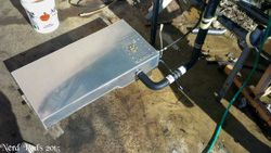
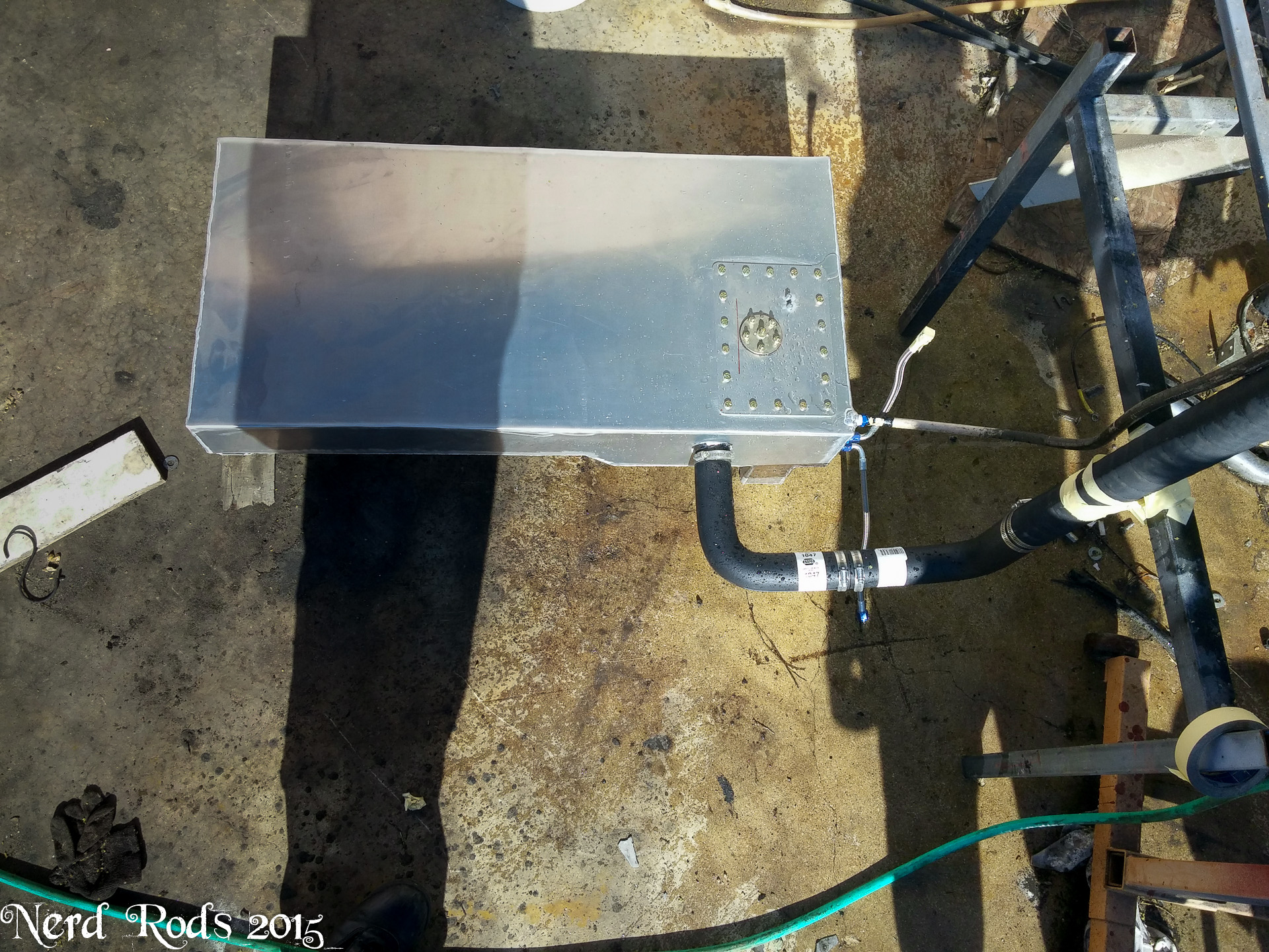
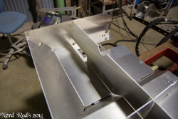
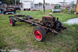
So we finally flow tested the gas tank. The shop water hose filed a 5 gallon bucket in 1:15. When I topped my bike of the other day it took 1:35 to fill 4 gallons so we're good there. We hooked it all up with all the bends to get up to the stock filler neck on the truck and let her rip. Test came out perfectly and we're good to go.

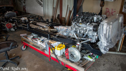
With that confirmed I ordered up 2 more tanks. We recently had frame #2 returned to us for completion. They had purchased it as a stage 2 for a father son project but with the son in high school they hadn't touched it. So it went from a stage 2, to a stage 3, and finally they asked for a stage 4 running chassis with a 5.3L LS and an automatic so one tank for them and one for stock. So you'll see some of their photos in here as well. The cool thing if I can swing it will be that George's is a tall body and The Webb's truck is a low body so if I do this right we can have some side by side stance photos soon.
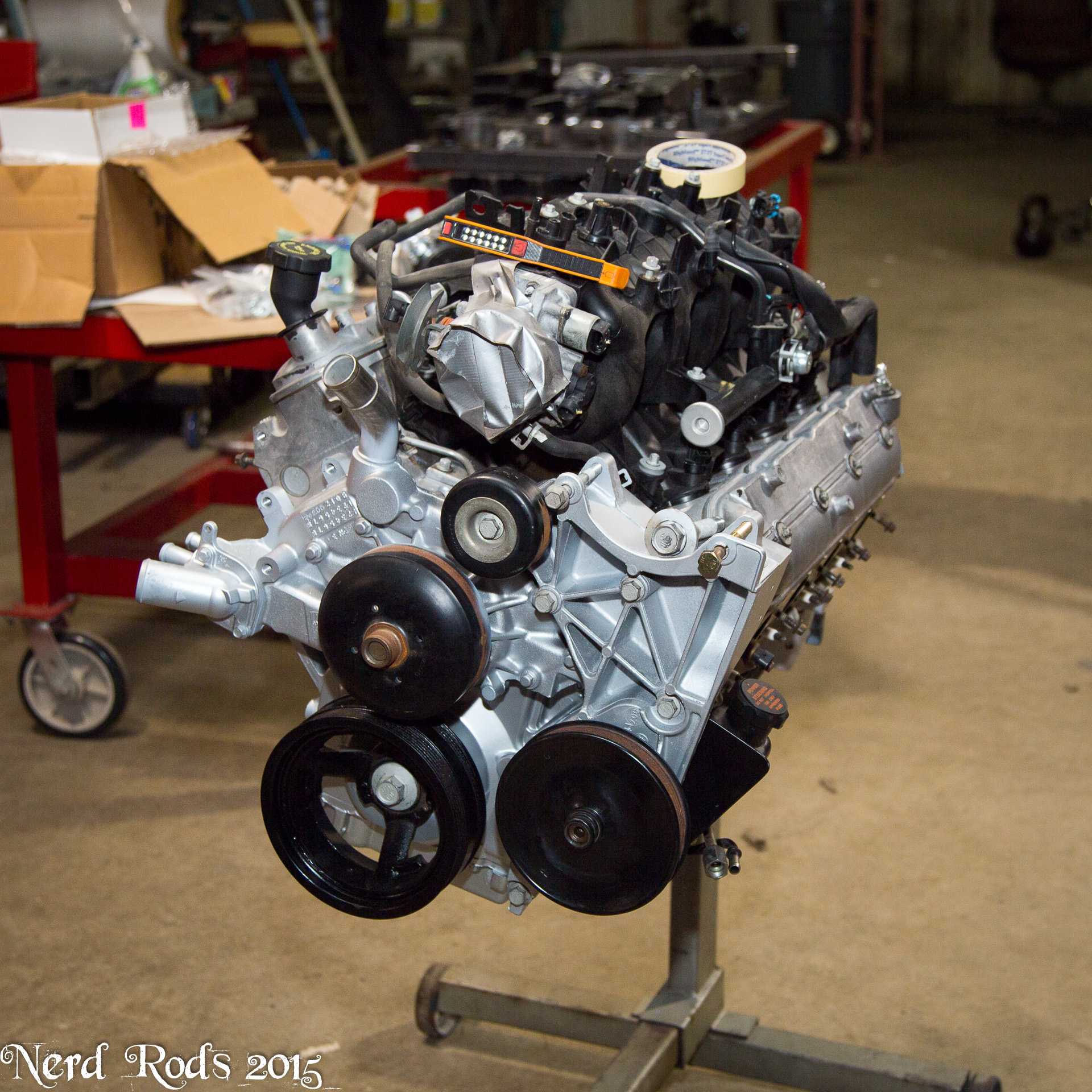
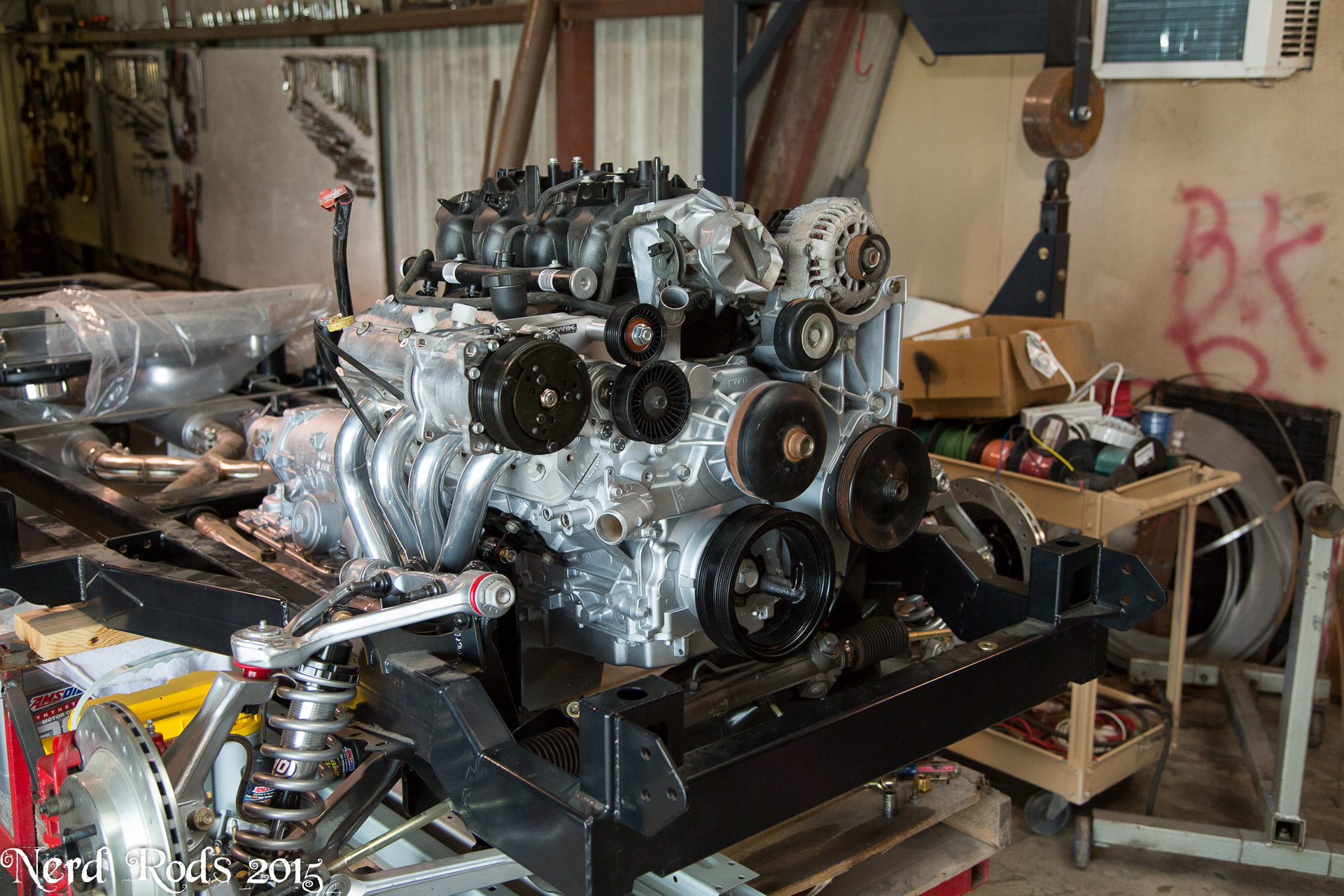
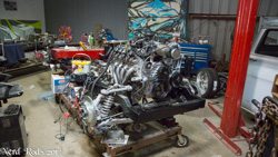
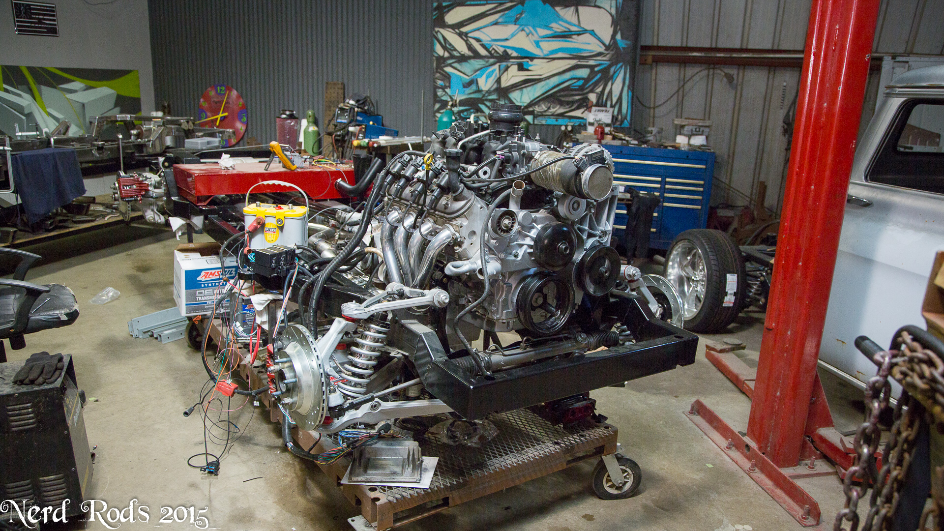
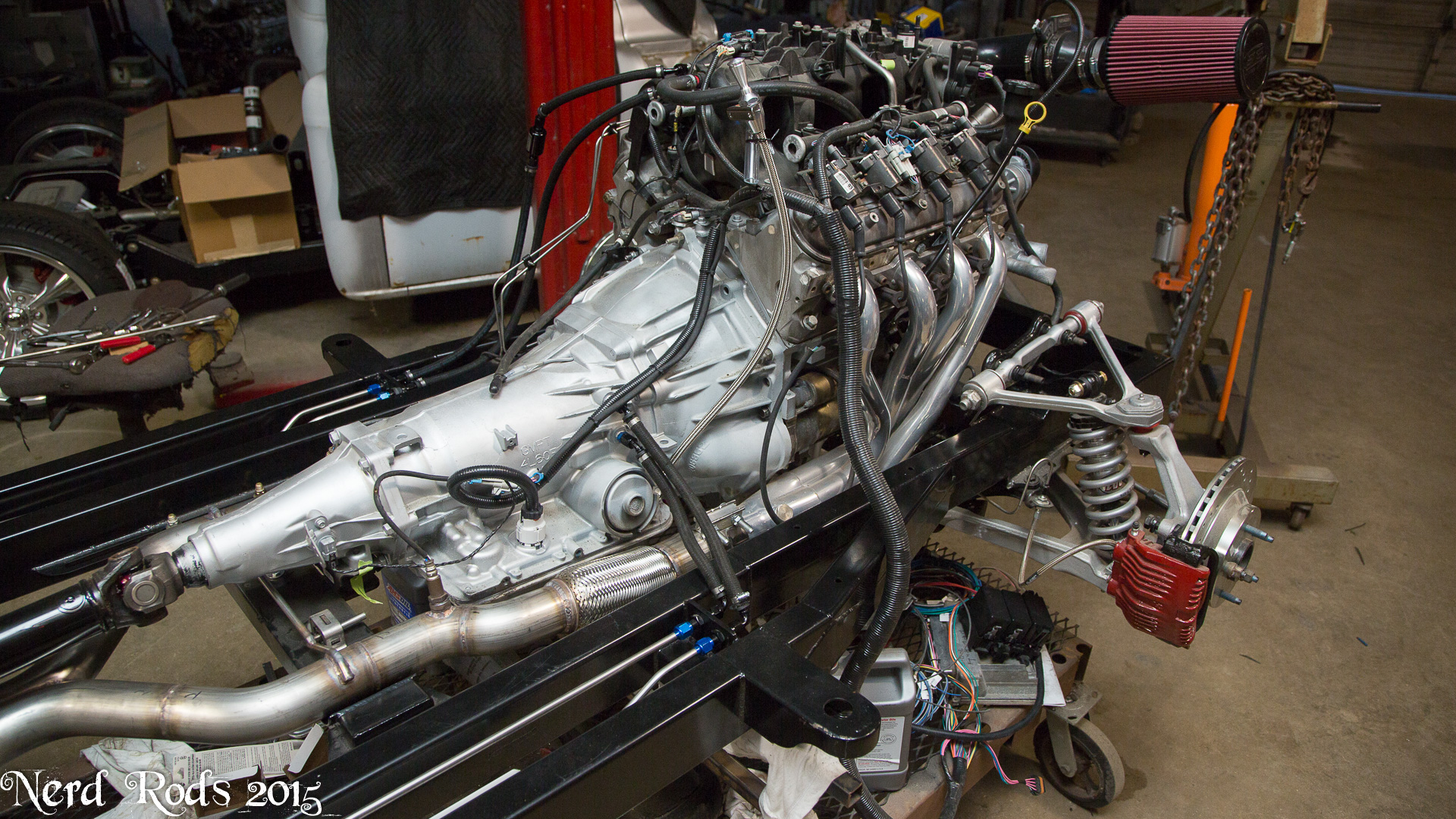
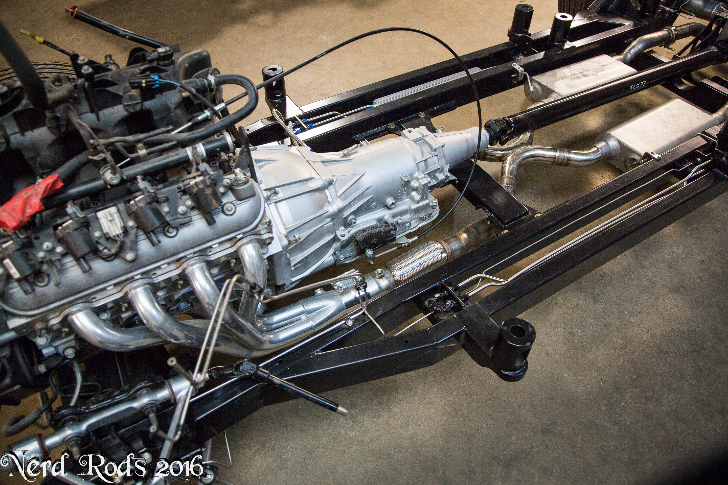
We got George's motor cleaned up and a coat of paint on it and the transmission to spruce it up a bit after the CAM swap. CAM, Push Rods, Valve Springs, and a light stall torque converter. But is all back together and in the frame for the last time

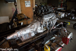
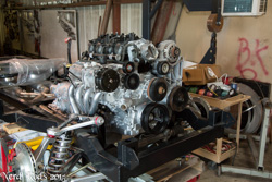
We're making up all the lines and fitting the radiator core. Coolant, Power Steering, Transmission and so forth will all be worked out now and then the body fitted so we're not monkeying around under the hood.

More to come soon, I've spent the last few months getting stock all worked out so we should flow through the project more quickly now.
George's Gallery http://gallery.nerdrods.com/Customer...George%20W/06/
The Webb's Gallery http://gallery.nerdrods.com/Customer...ake%20Webb/01/
Later
-Russell

With that confirmed I ordered up 2 more tanks. We recently had frame #2 returned to us for completion. They had purchased it as a stage 2 for a father son project but with the son in high school they hadn't touched it. So it went from a stage 2, to a stage 3, and finally they asked for a stage 4 running chassis with a 5.3L LS and an automatic so one tank for them and one for stock. So you'll see some of their photos in here as well. The cool thing if I can swing it will be that George's is a tall body and The Webb's truck is a low body so if I do this right we can have some side by side stance photos soon.
We got George's motor cleaned up and a coat of paint on it and the transmission to spruce it up a bit after the CAM swap. CAM, Push Rods, Valve Springs, and a light stall torque converter. But is all back together and in the frame for the last time

We're making up all the lines and fitting the radiator core. Coolant, Power Steering, Transmission and so forth will all be worked out now and then the body fitted so we're not monkeying around under the hood.


More to come soon, I've spent the last few months getting stock all worked out so we should flow through the project more quickly now.
George's Gallery http://gallery.nerdrods.com/Customer...George%20W/06/
The Webb's Gallery http://gallery.nerdrods.com/Customer...ake%20Webb/01/
Later
-Russell
04-08-2015 | 01:55 PM
#103

TECH Resident
Joined: Feb 2014
Posts: 954
Likes: 9
From: Encinitas CA
Your builds and products are so cool. Love them. Was thinking a complementary product would a back-half subframe kit for a Gen1 Camaro to install the corvette IRS.
Keep up the great work!
Was thinking of building my own fuel tank for my '51. Presently, I have a plastic 12 gallon fuel cell. I'd prefer to have 20 gallons +.
Are you using 5052 aluminum 1/8" wall?
How do you keep the sides of the tank from warping when you weld up the tank? Do you do just a few inches at a time, or hold the whole thing in a jig?
thanks,
Doug
04-09-2015 | 12:52 PM
#104
Thread Starter
Launching!
Joined: Jan 2007
Posts: 294
Likes: 3
From: Luling TX In the Hot Rod Shop
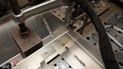
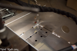
5052 0.090" Its easier to bend on 48" long runs and keep it square left to right.
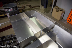
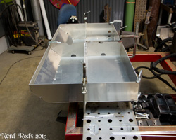
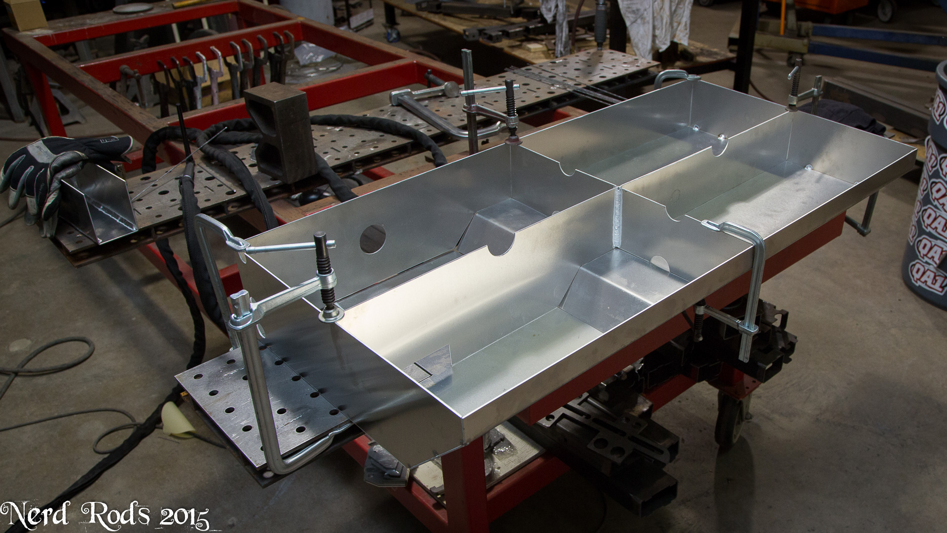
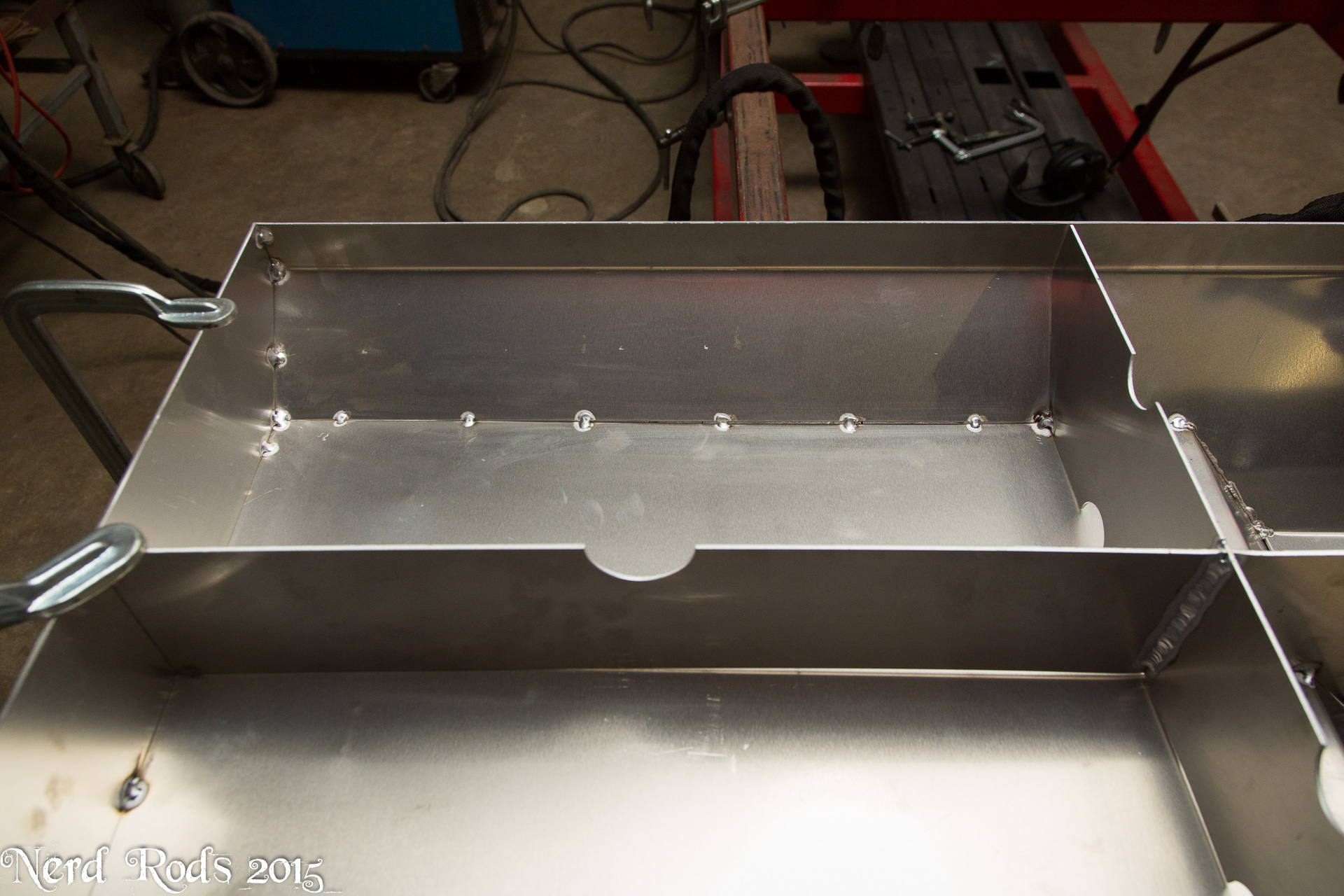
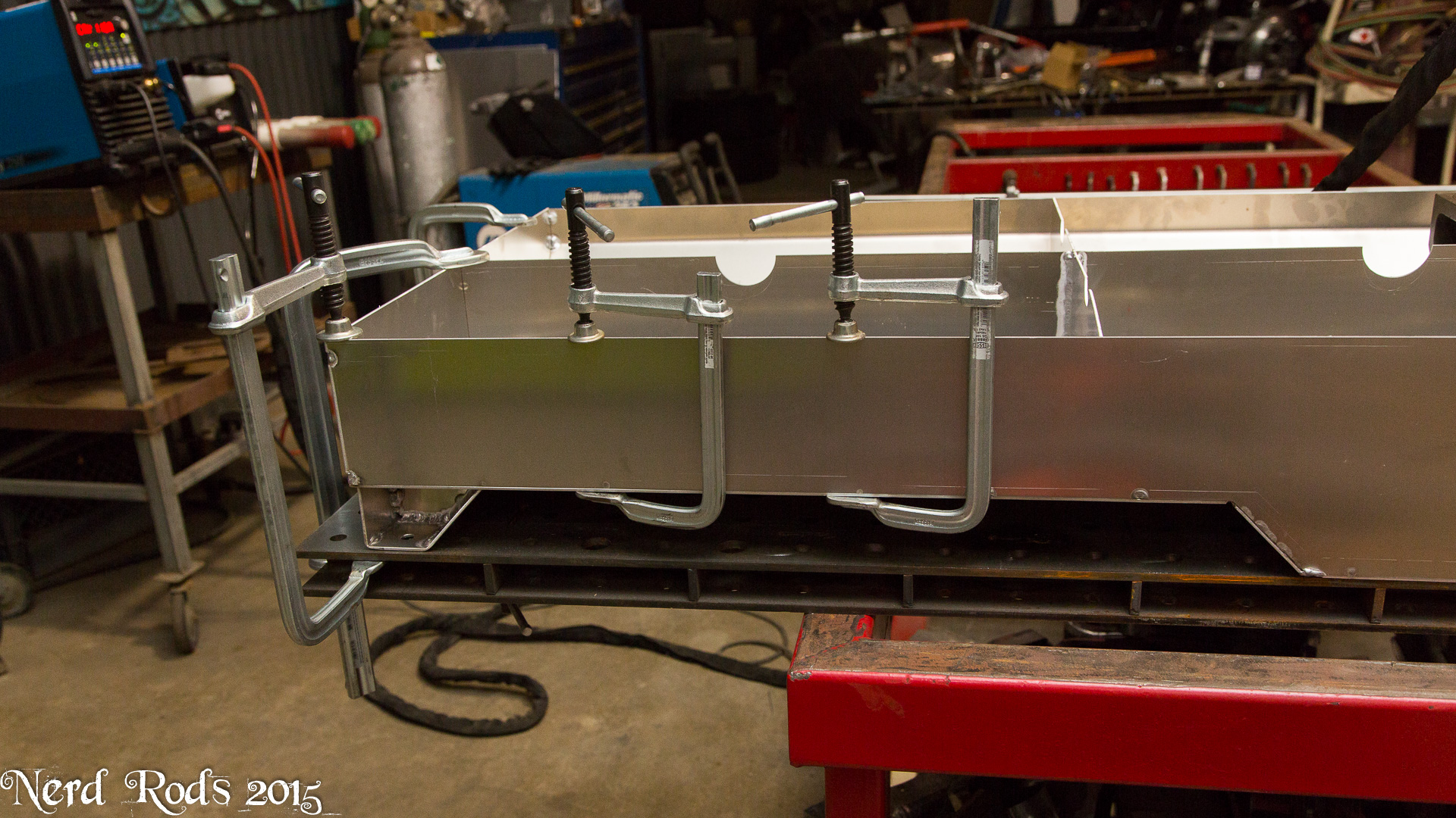
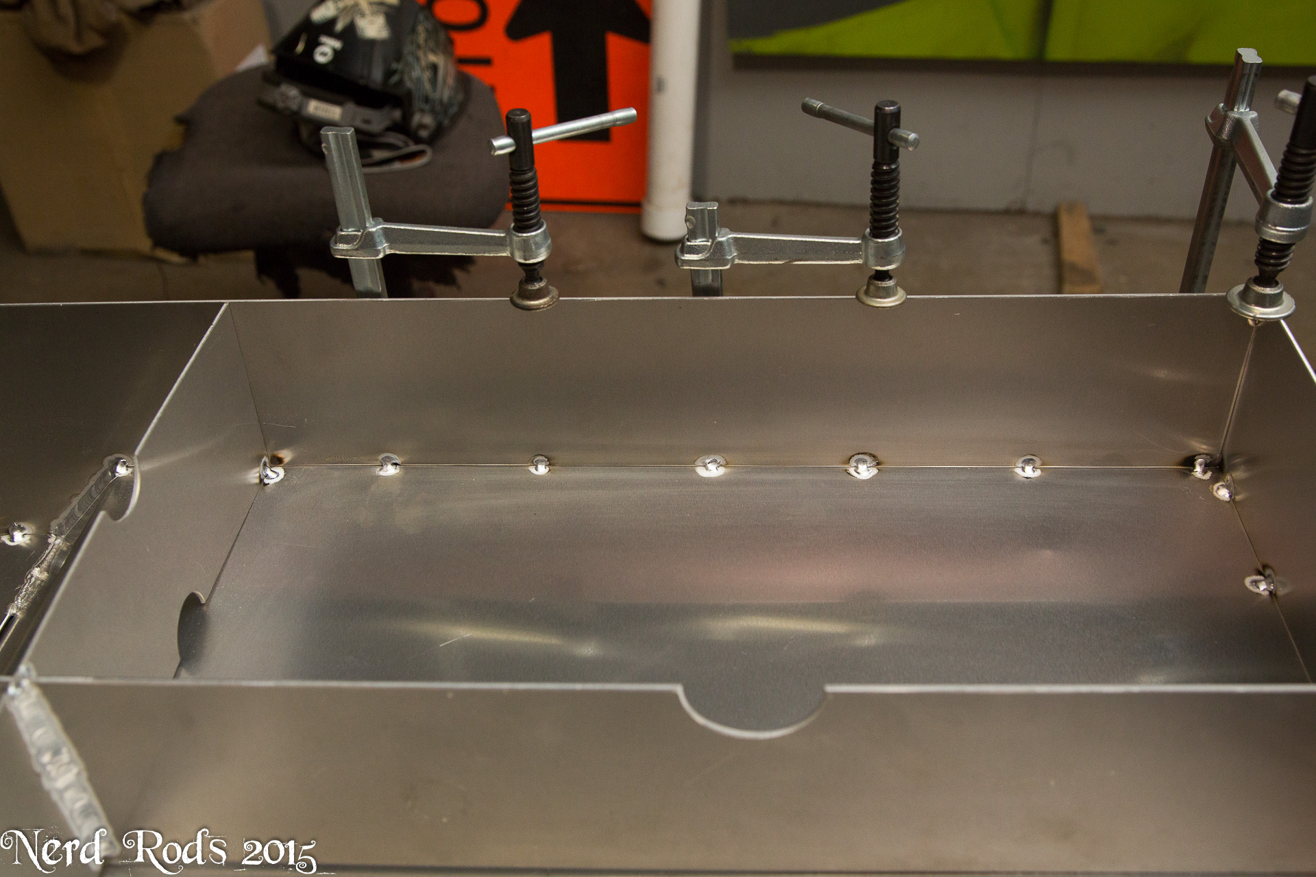
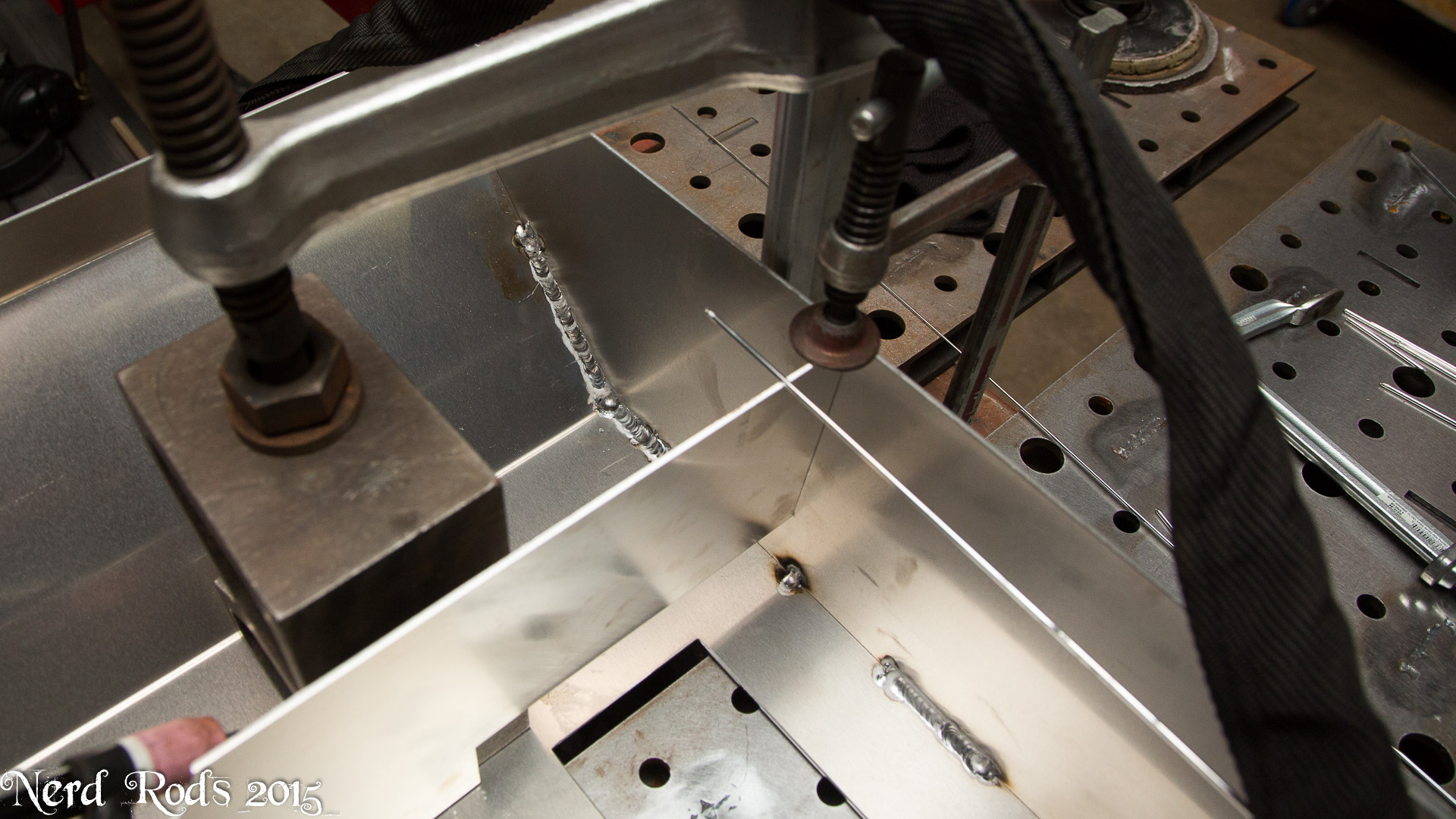
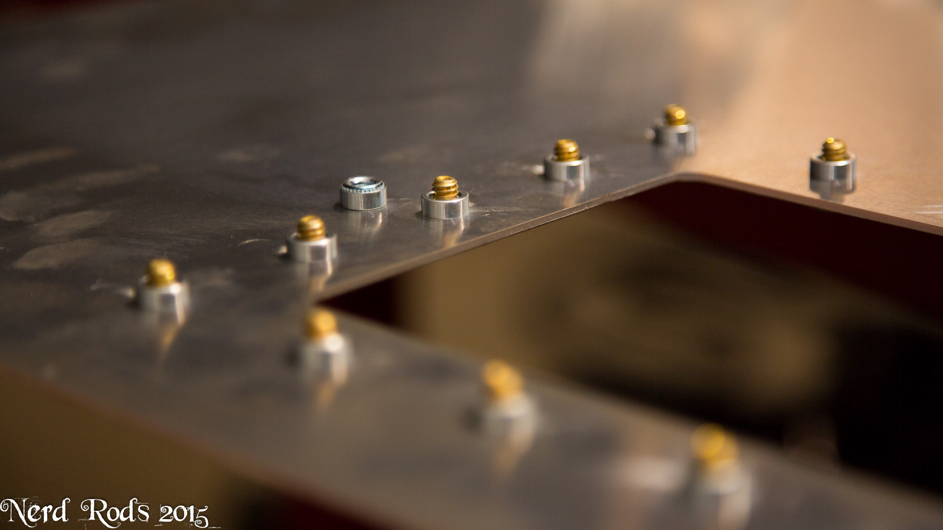
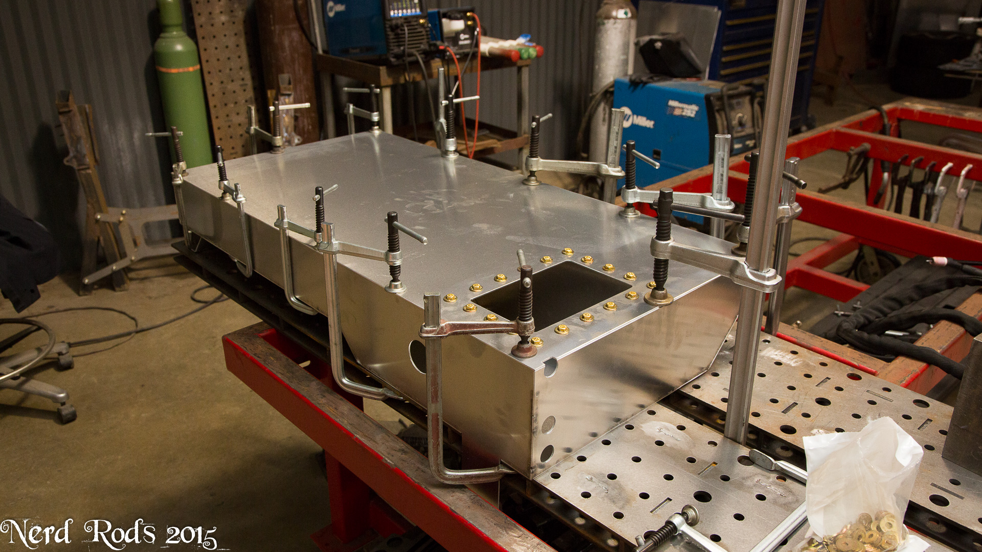
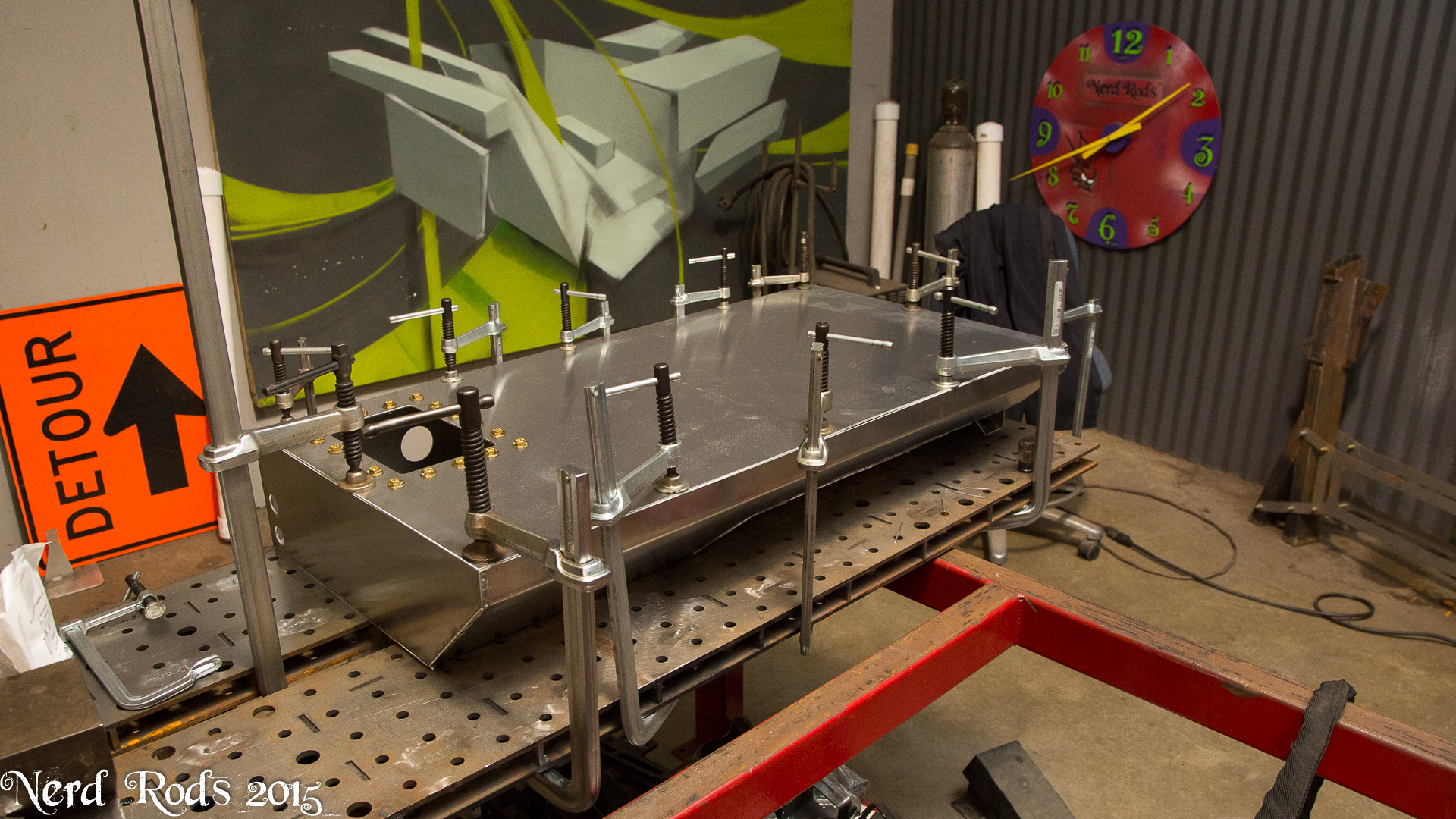
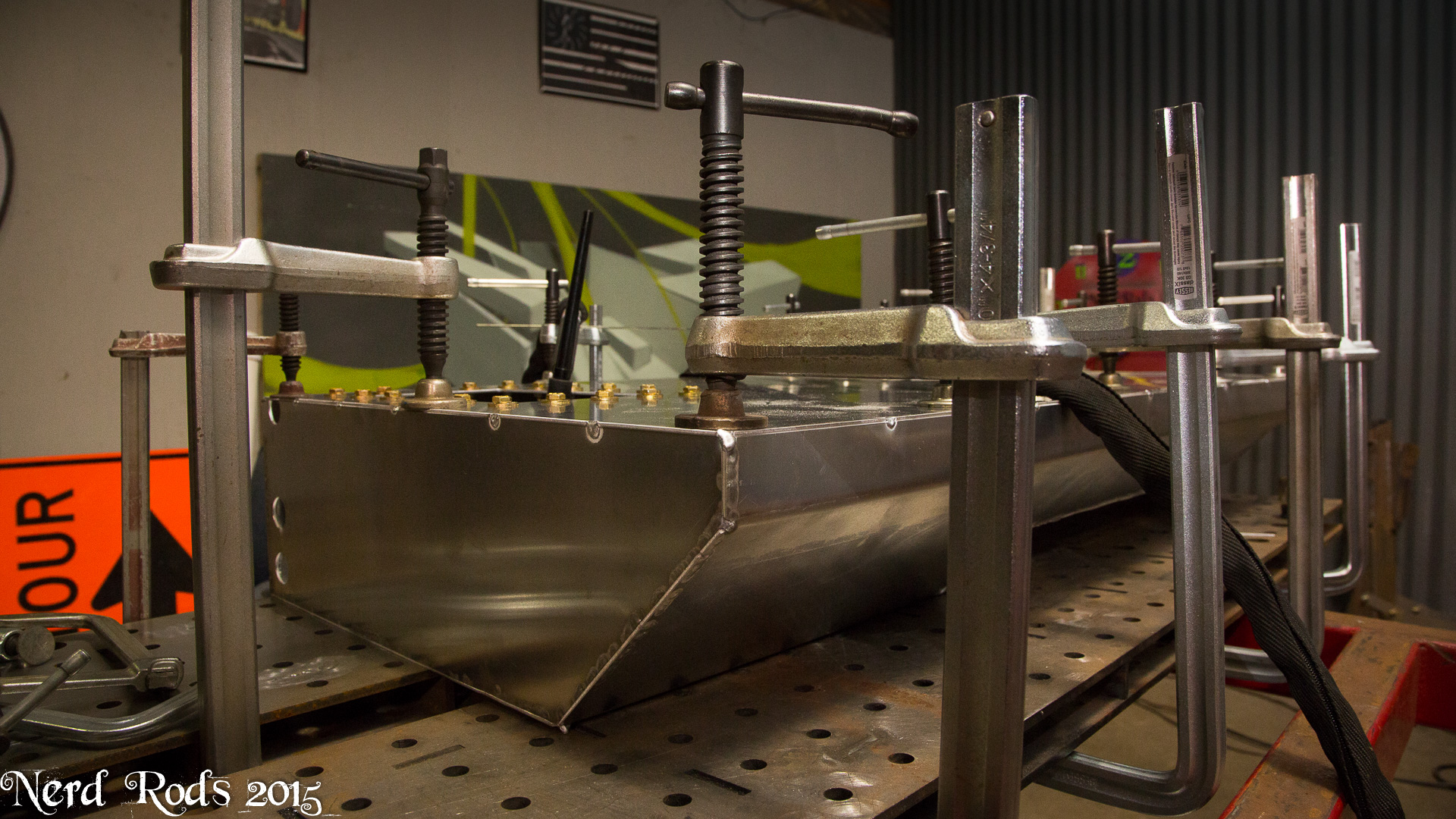
I start by tacking every 5-6 inches then bonce around in between these sections to complete it. I also claim 15k in clamps on my shop insurance and my frame building tables help too. Keeping it square while doing the first welding and welding the inside verticals and bottom where all the stress is it also key. And don't worry if its a little out of square, its only a box with **** in it, not a loaded suspension component. If my tanks are �.250 I don't loose any sleep on it but normally �.125 is easy to keep if you take a little more time than normal.
Later
-Russell

 04-13-2015 | 11:05 AM
#106
TECH Resident
Joined: Feb 2014
Posts: 954
Likes: 9
From: Encinitas CA
5052 0.090" Its easier to bend on 48" long runs and keep it square left to right.
I start by tacking every 5-6 inches then bonce around in between these sections to complete it. I also claim 15k in clamps on my shop insurance and my frame building tables help too. Keeping it square while doing the first welding and welding the inside verticals and bottom where all the stress is it also key. And don't worry if its a little out of square, its only a box with **** in it, not a loaded suspension component. If my tanks are �.250 I don't loose any sleep on it but normally �.125 is easy to keep if you take a little more time than normal.
Later
-Russell
Appreciate the info - yeah I figured it doesn't have to be perfect and I will mount it on rubber mounts to minimize vibrations. Do I understand that you weld the inside verticals and bottoms and then also weld those outside later? Forgive me if that's a dumb question, as it is first thing Monday morning after a vacation for me.

Thank you much,
Doug
04-14-2015 | 09:51 AM
#107

Teching In
Joined: Apr 2014
Posts: 10
Likes: 1
Watch this
Then think about the offset on the diff. Remember your pinion is already offset left to right on the diff to have equal length half shafts and the transmission is centered so no need to have compound angles by angling the diff as well. And the transmission ends up just a touch higher so you don't want that frequency generation to happen on your car.
Then think about the offset on the diff. Remember your pinion is already offset left to right on the diff to have equal length half shafts and the transmission is centered so no need to have compound angles by angling the diff as well. And the transmission ends up just a touch higher so you don't want that frequency generation to happen on your car.
The reason I ask, old school rule of thumb, level the carburetor, which is usually a few degrees down on the crank, then match the pinion angle. If I end up with an LS 5.3, do I install the engine level? Does crankshaft angle have gyroscopic effect on handling? Maybe I'm over thinking this.
Thanks for the update.
04-14-2015 | 11:37 PM
#108
Thread Starter
Launching!
Joined: Jan 2007
Posts: 294
Likes: 3
From: Luling TX In the Hot Rod Shop
Hi Russell,
Appreciate the info - yeah I figured it doesn't have to be perfect and I will mount it on rubber mounts to minimize vibrations. Do I understand that you weld the inside verticals and bottoms and then also weld those outside later? Forgive me if that's a dumb question, as it is first thing Monday morning after a vacation for me.
Thank you much,
Doug
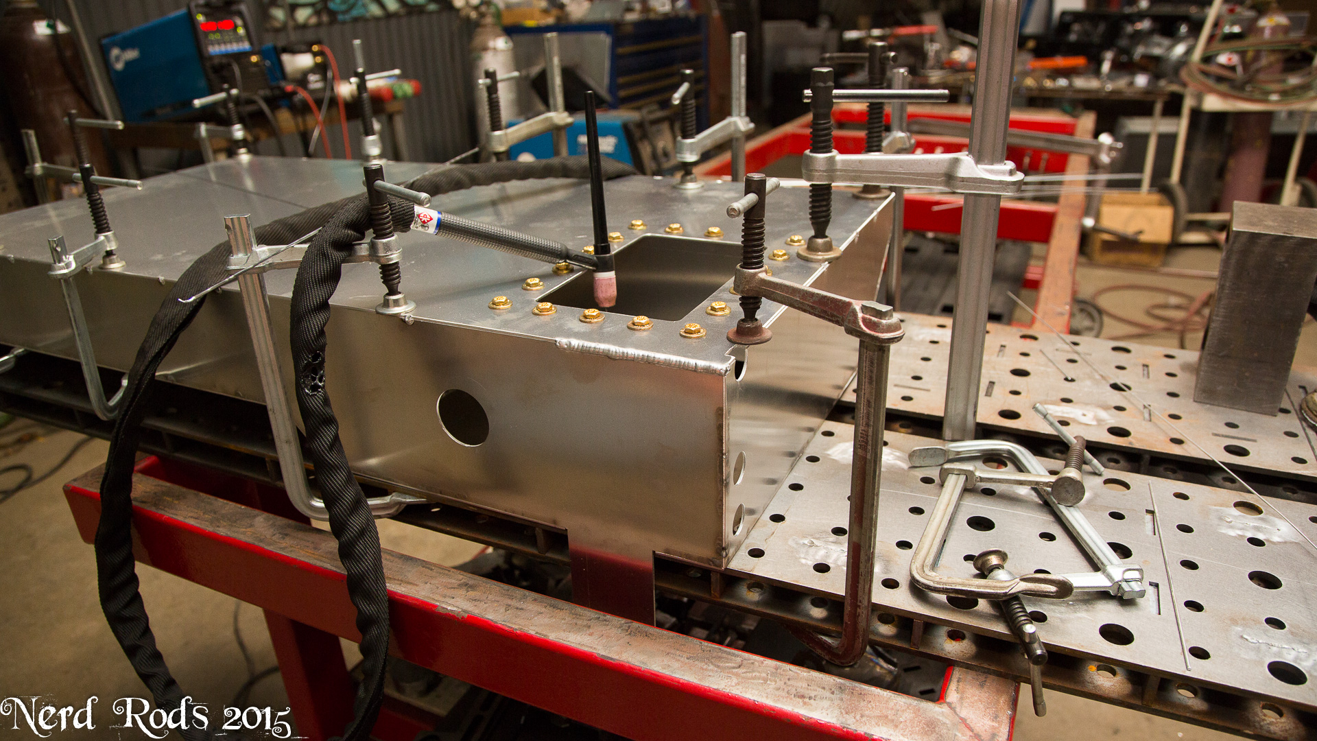
Also, I'm working on a tank right now for the second stage 4 chassis right now actually so I'll take some photos to make more since of how I do it instead of writing a book on it here.
The reason I ask, old school rule of thumb, level the carburetor, which is usually a few degrees down on the crank, then match the pinion angle. If I end up with an LS 5.3, do I install the engine level? Does crankshaft angle have gyroscopic effect on handling? Maybe I'm over thinking this.
Thanks for the update.
Thanks for the update.
Later
-Russell
04-22-2015 | 09:26 AM
#109
Thread Starter
Launching!
Joined: Jan 2007
Posts: 294
Likes: 3
From: Luling TX In the Hot Rod Shop
We�ll we�re waiting on a few things from the customer, namely the wheels, a final paint decision and some final budgeting plans for the level of finish out we�re going to be doing. So my hands are tired on a few things for now but the Webb�s truck will be getting the spot light for the time being so we should have two running trucks driving out of the shop shortly, one high and one low body stance.
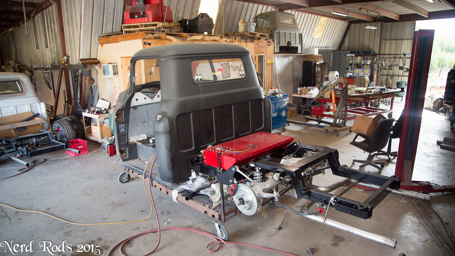
So we�ve got the body on the frame now and we�re stared hooking up the final systems and doing the final checks on clearances for our kits so we can finalize the designs on those.

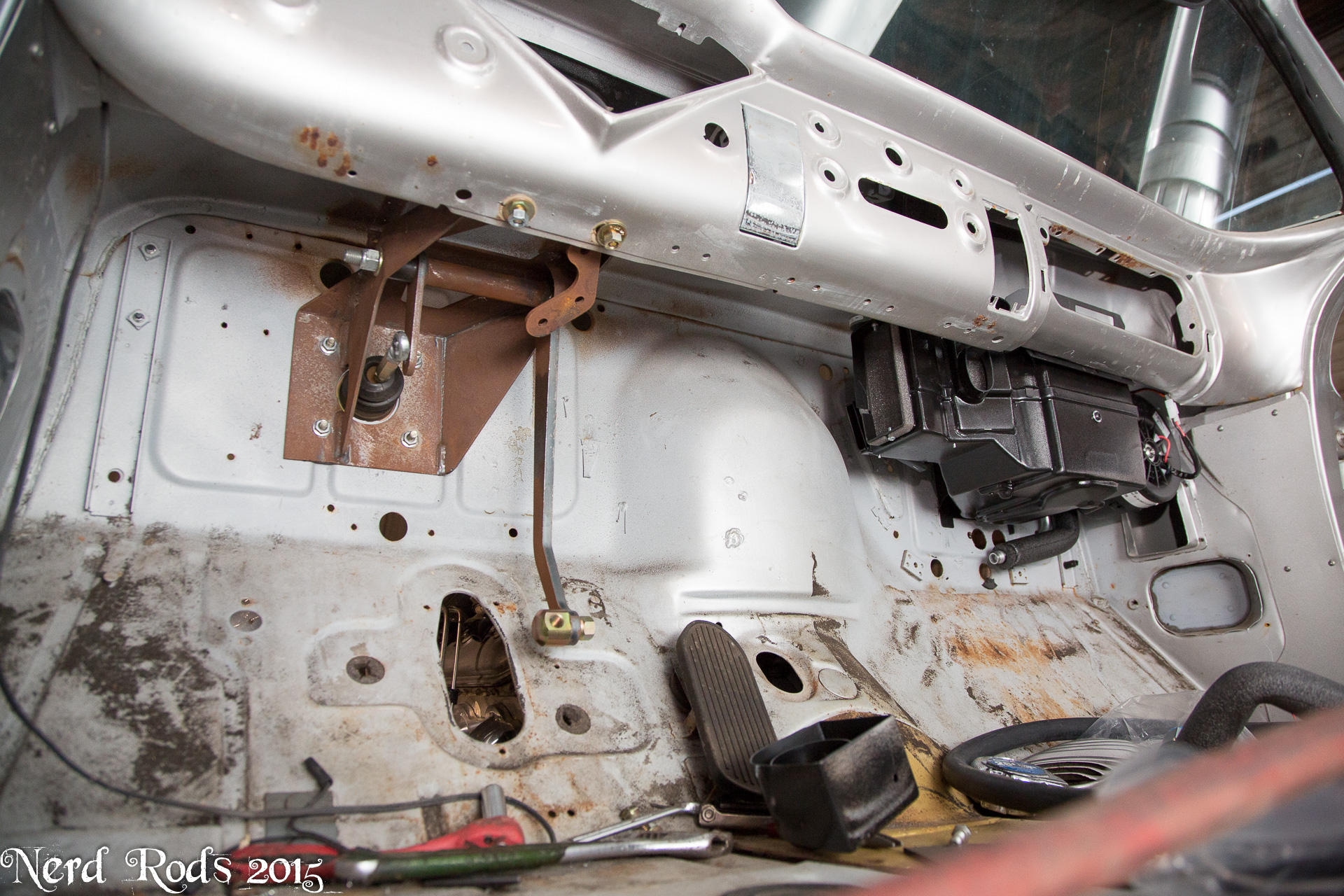
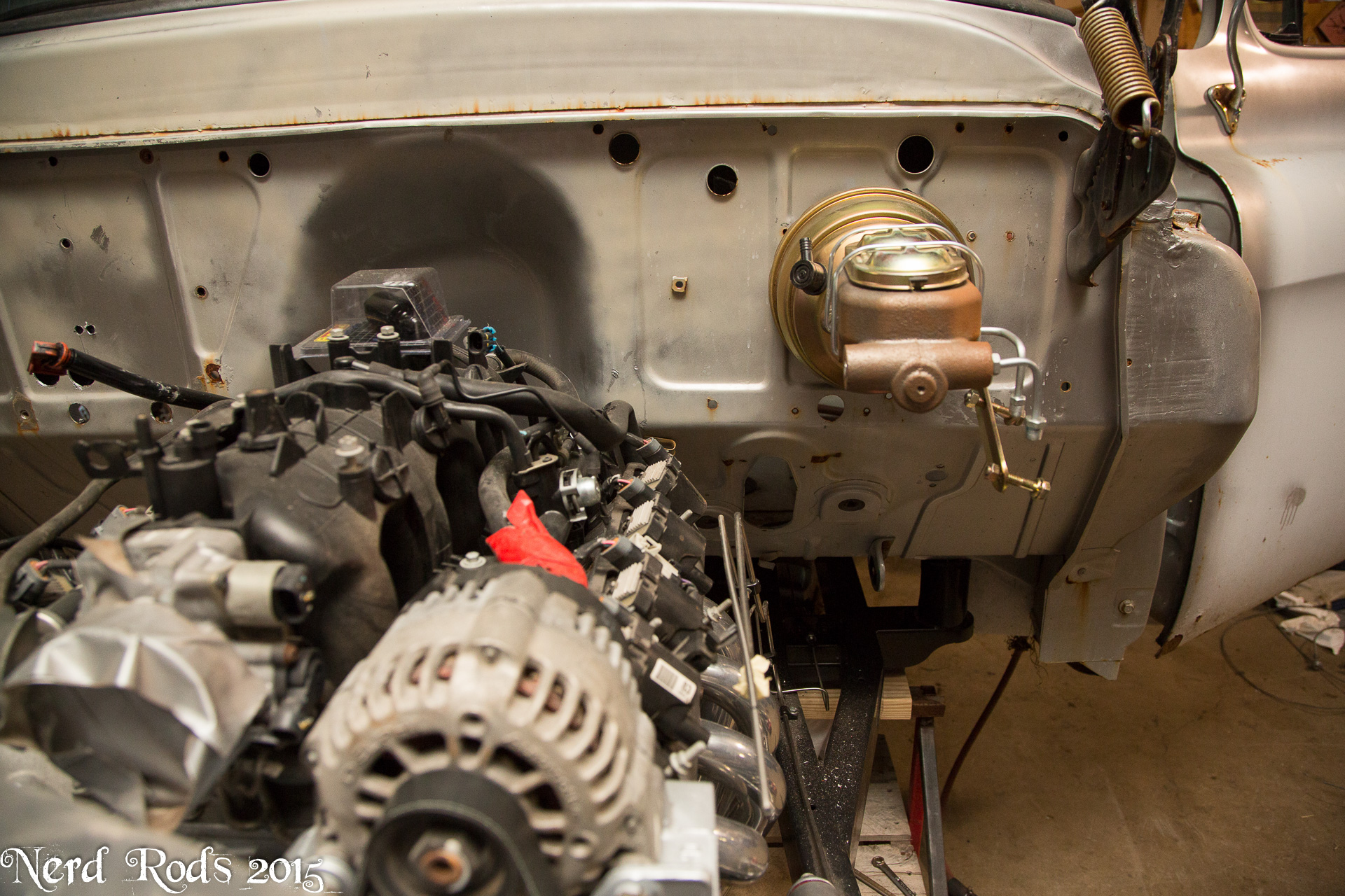
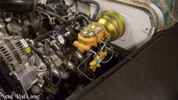
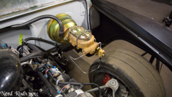
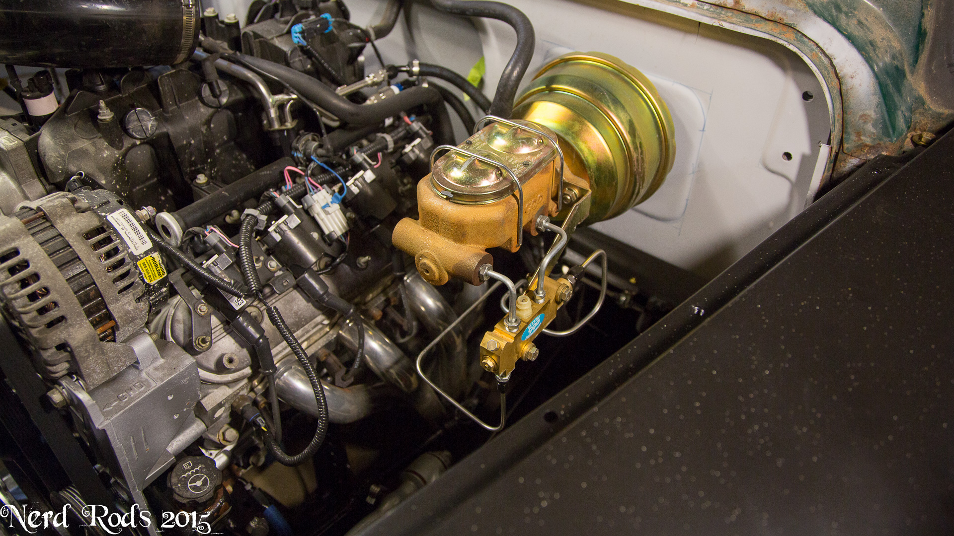
The CCP firewall mounted break pedal goes in beautifully but there are almost no instructions about it so Jim is going to do a video about its installation. While the frame in its high body placement is a no body modification fit you will still need to install the firewall master cylinder and that reacquires cutting on your body. So we want a video showing that so people will know what modifications are needed and specifically how hard they are. Jim said he should be able to do the next one in 30 minutes so look forward to that.
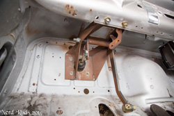
There is also a lot of room to the engine that we don�t normally have on the TriFive�s so larger systems like the 8� or 9� boosters are an option here for people who want some serious braking power.
So we�ve got the body on the frame now and we�re stared hooking up the final systems and doing the final checks on clearances for our kits so we can finalize the designs on those.
The CCP firewall mounted break pedal goes in beautifully but there are almost no instructions about it so Jim is going to do a video about its installation. While the frame in its high body placement is a no body modification fit you will still need to install the firewall master cylinder and that reacquires cutting on your body. So we want a video showing that so people will know what modifications are needed and specifically how hard they are. Jim said he should be able to do the next one in 30 minutes so look forward to that.


There is also a lot of room to the engine that we don�t normally have on the TriFive�s so larger systems like the 8� or 9� boosters are an option here for people who want some serious braking power.

 05-19-2015 | 03:54 AM
#110
Thread Starter
Launching!
Joined: Jan 2007
Posts: 294
Likes: 3
From: Luling TX In the Hot Rod Shop
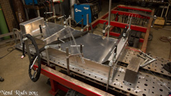
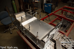
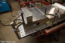
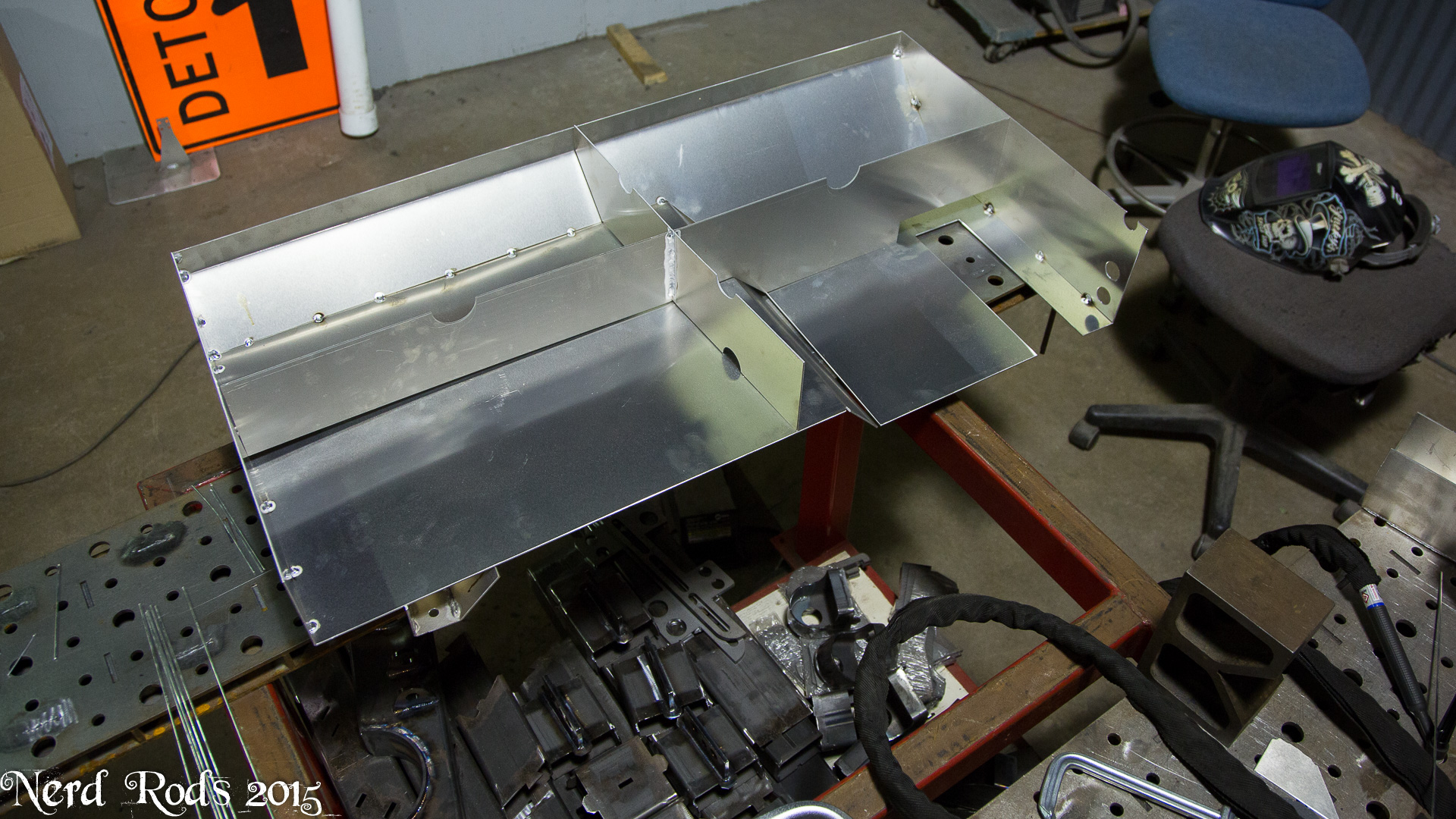
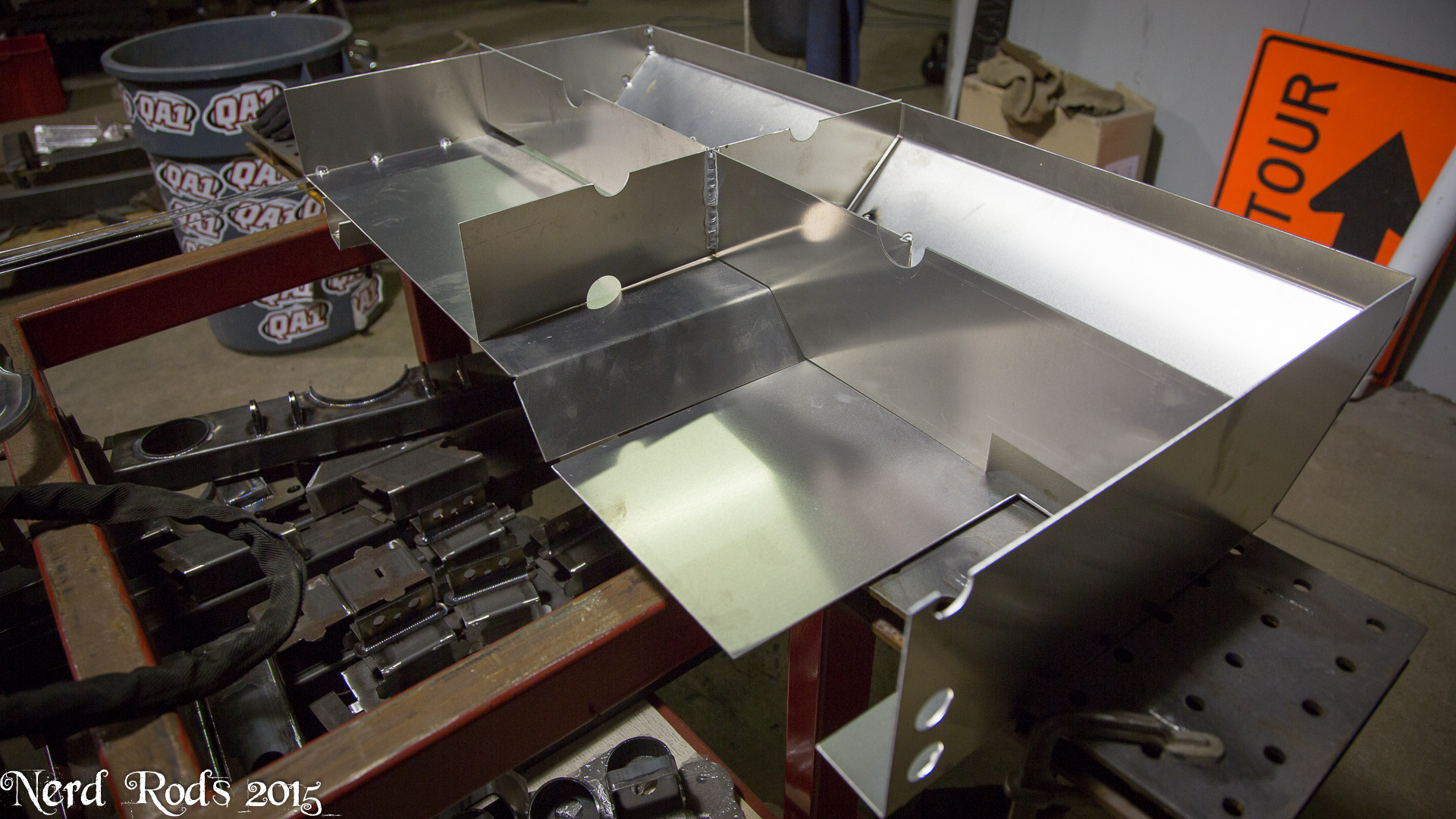
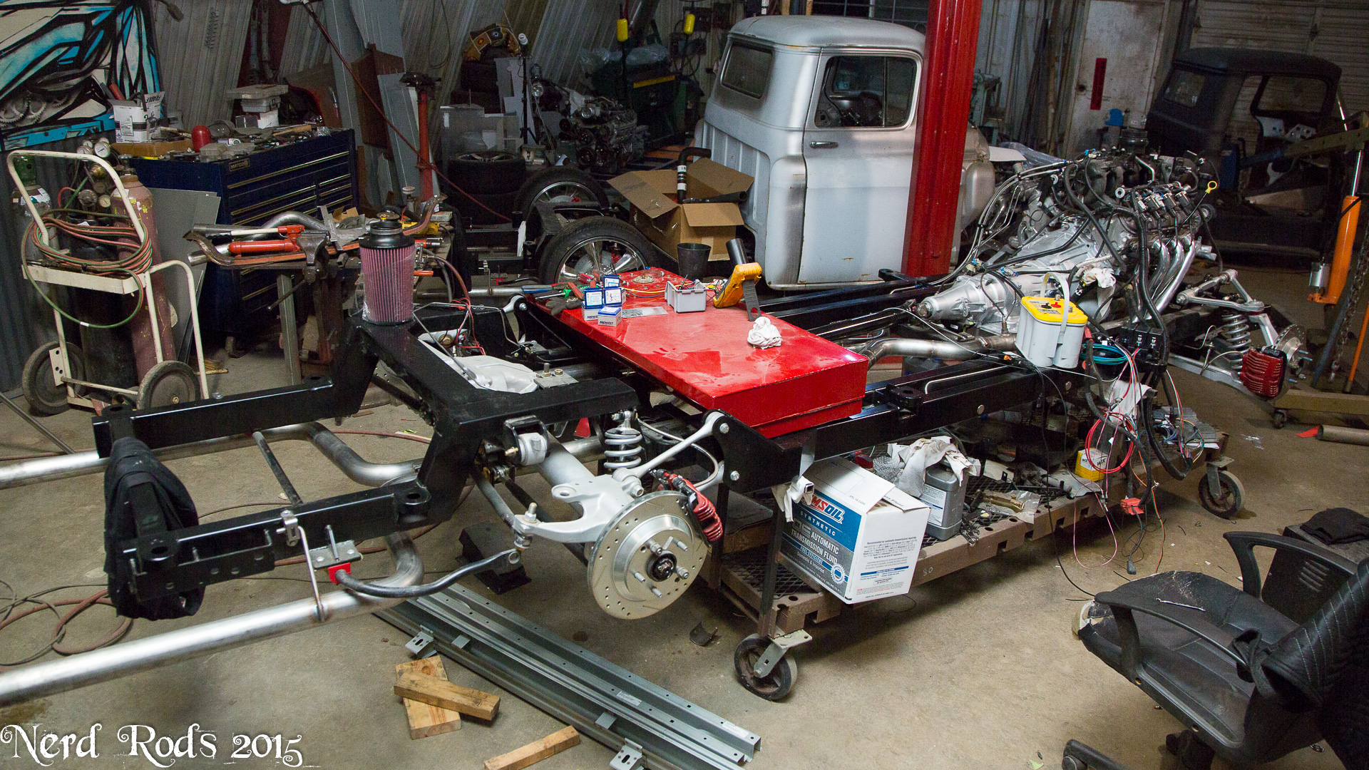
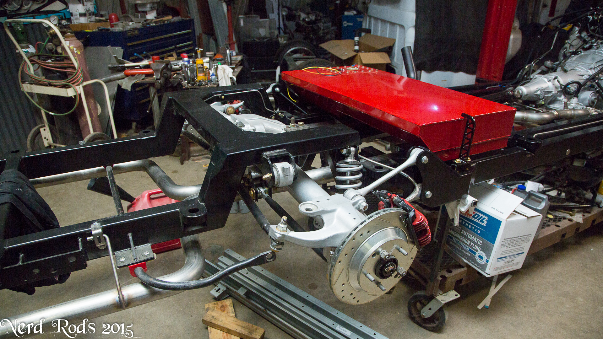
Wow its been a little while but we're gotten a bit done on Georges 56 and the Webb's 55. I'm really excited to see the tall and low bodies sitting side by side soon. Wheels are on the way for both and so that should be happening soon.
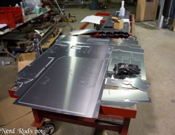
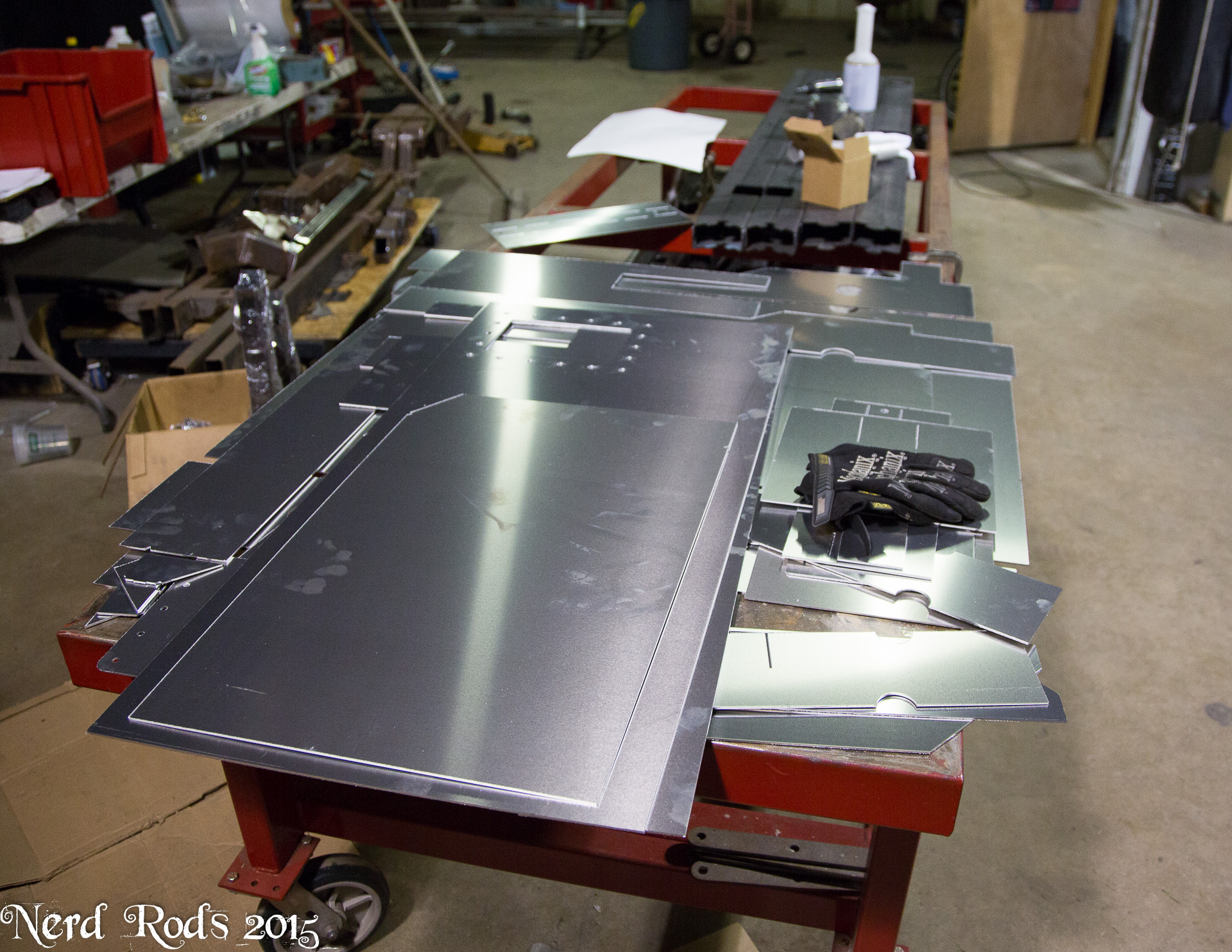
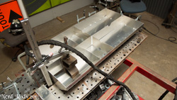
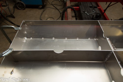
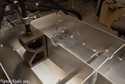
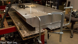
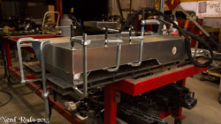
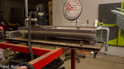
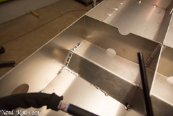
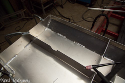
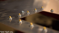
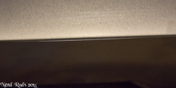
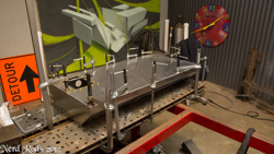
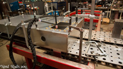
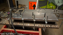
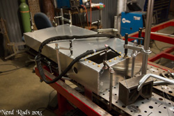
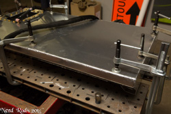
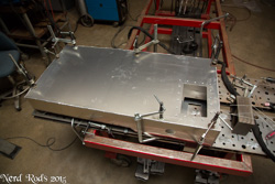
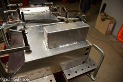
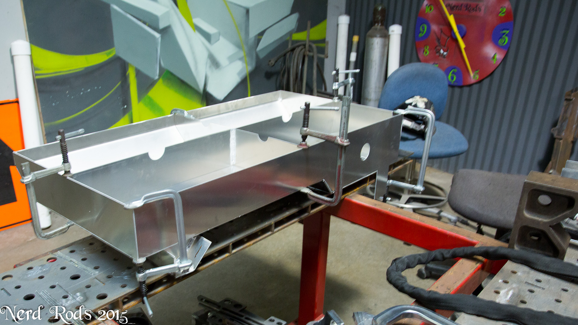
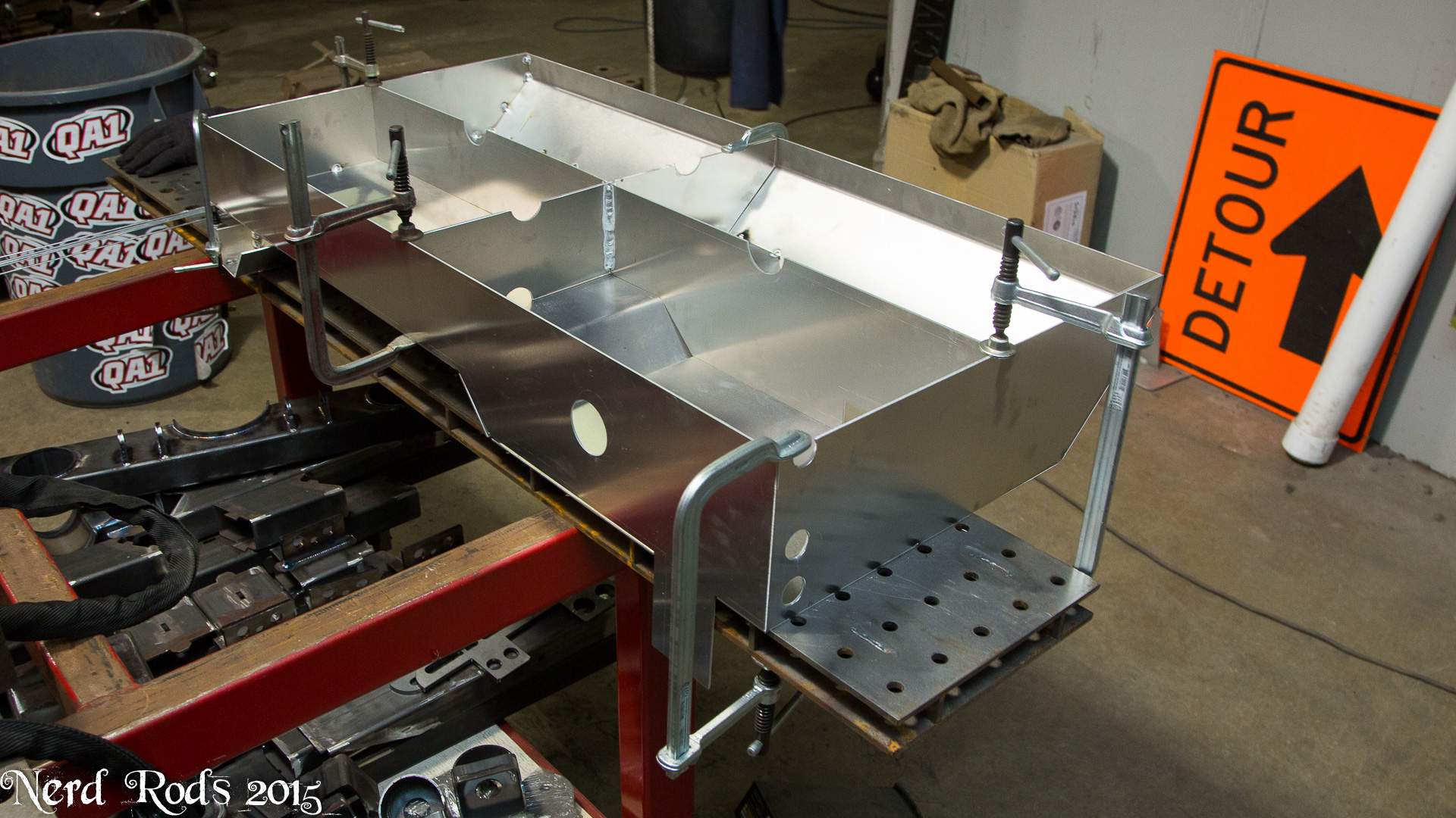
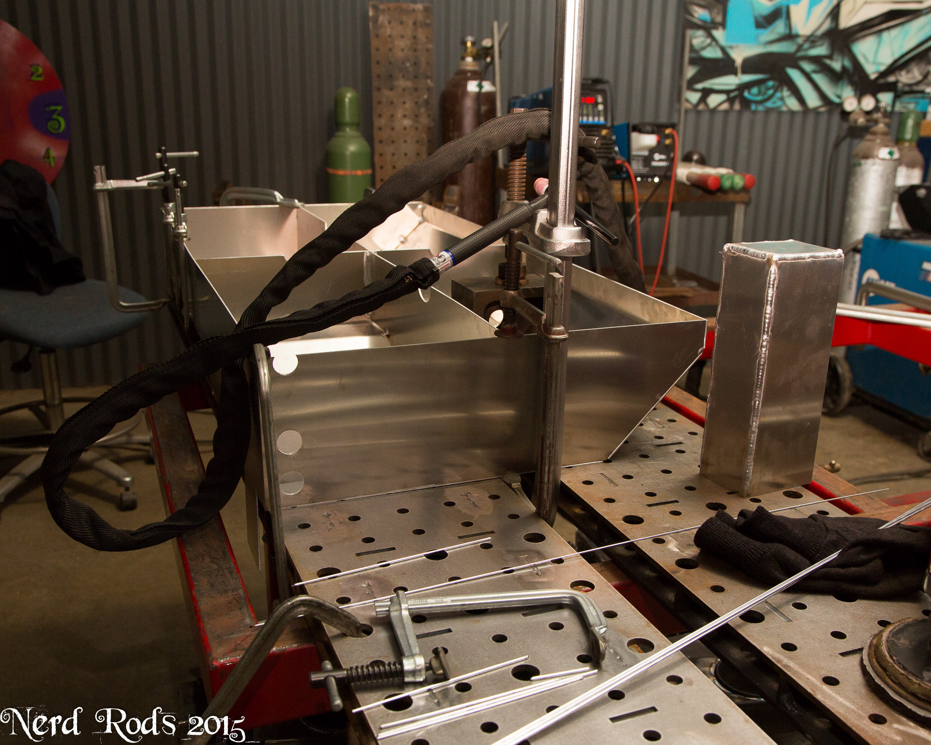
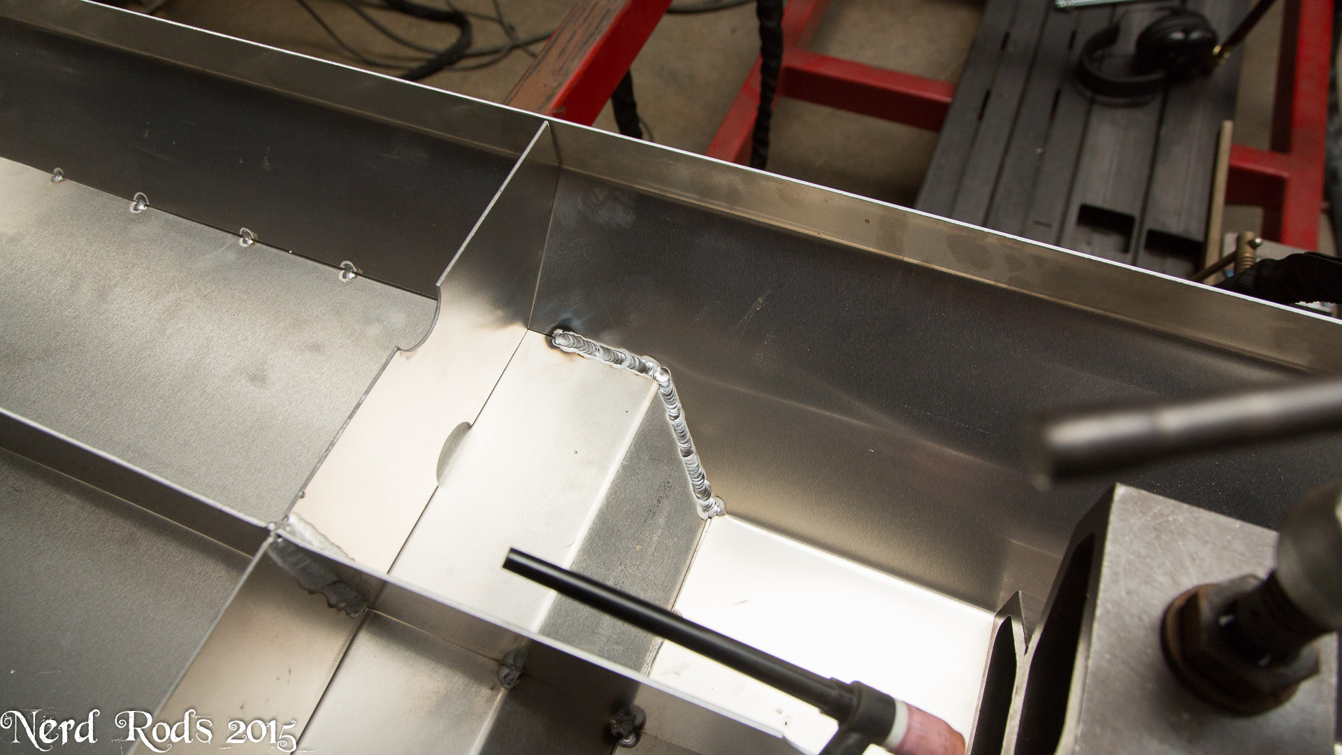
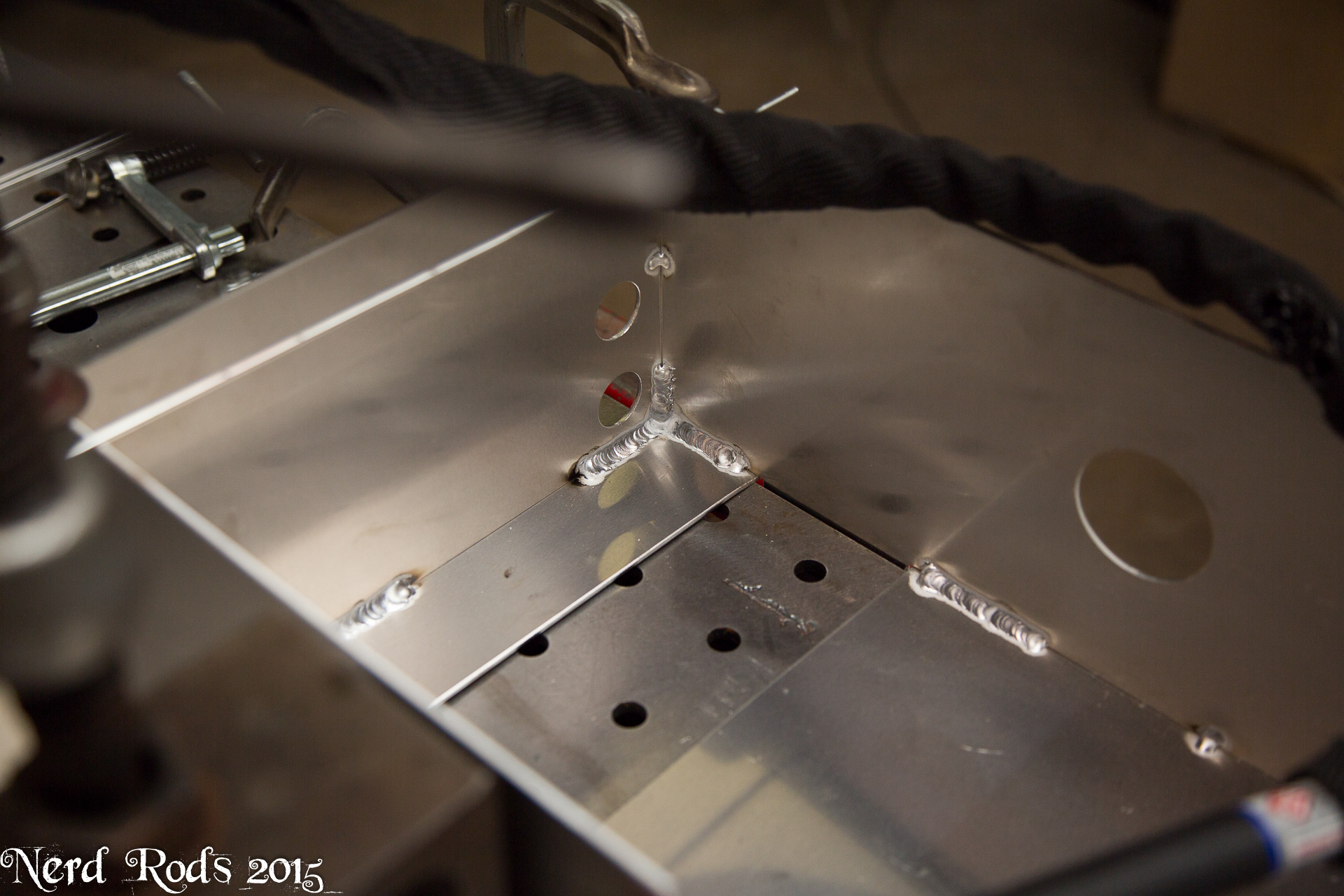
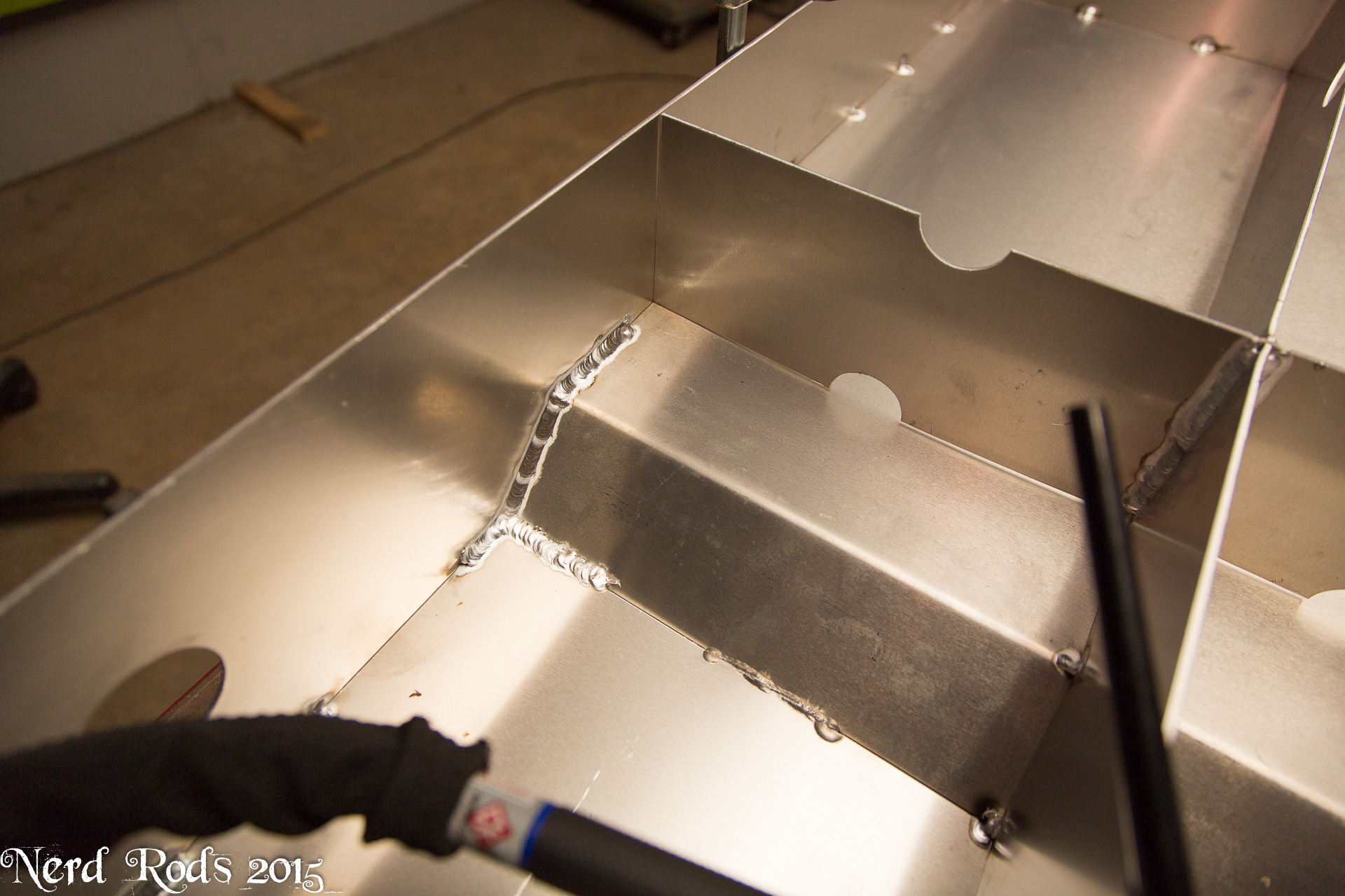
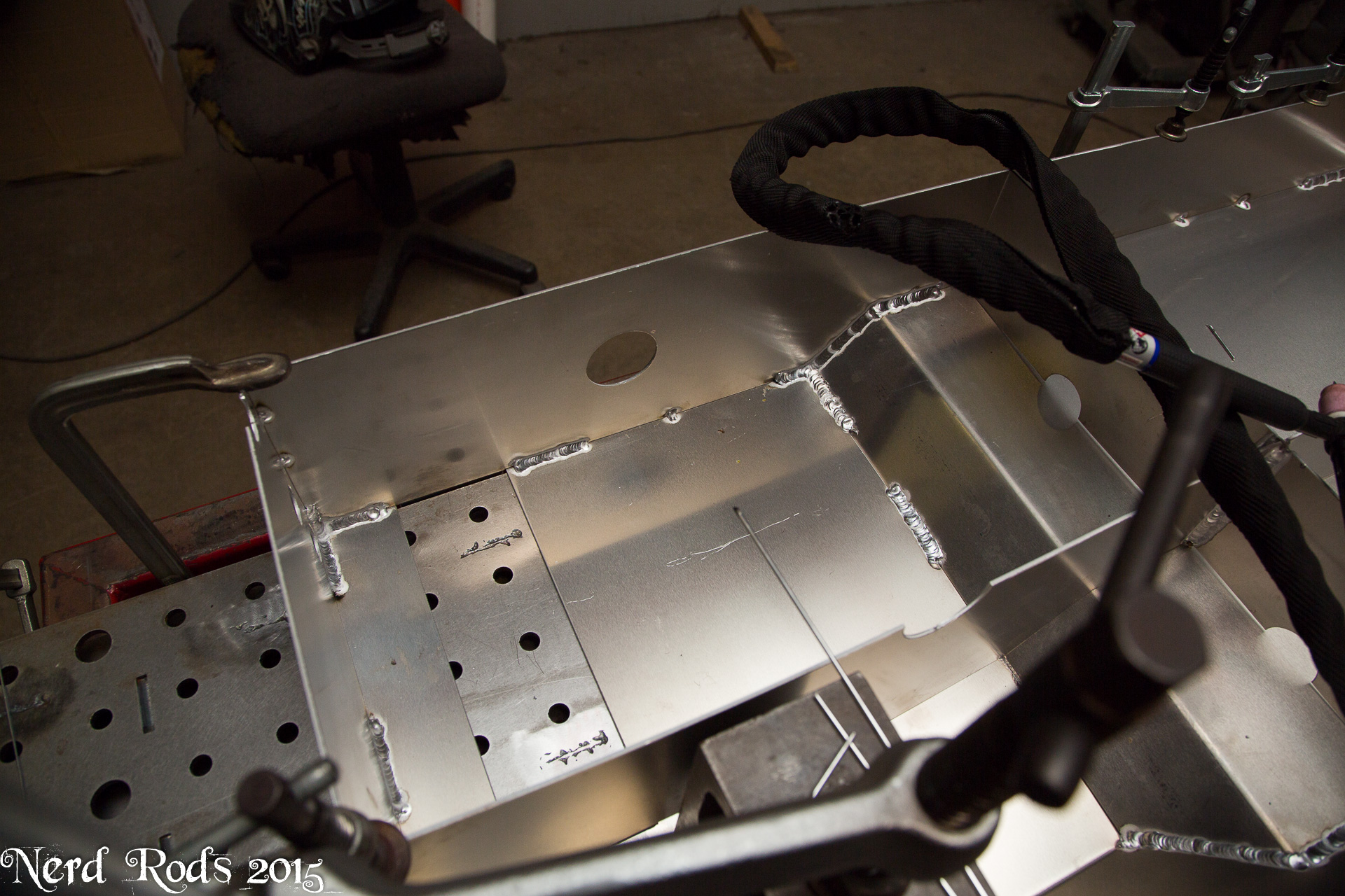
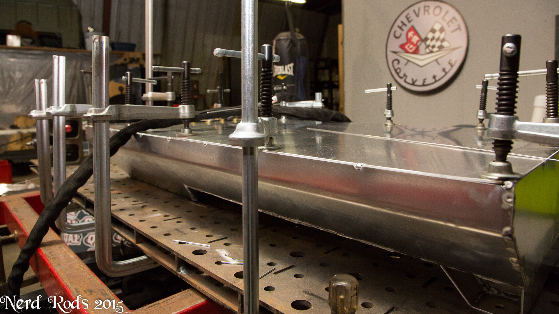
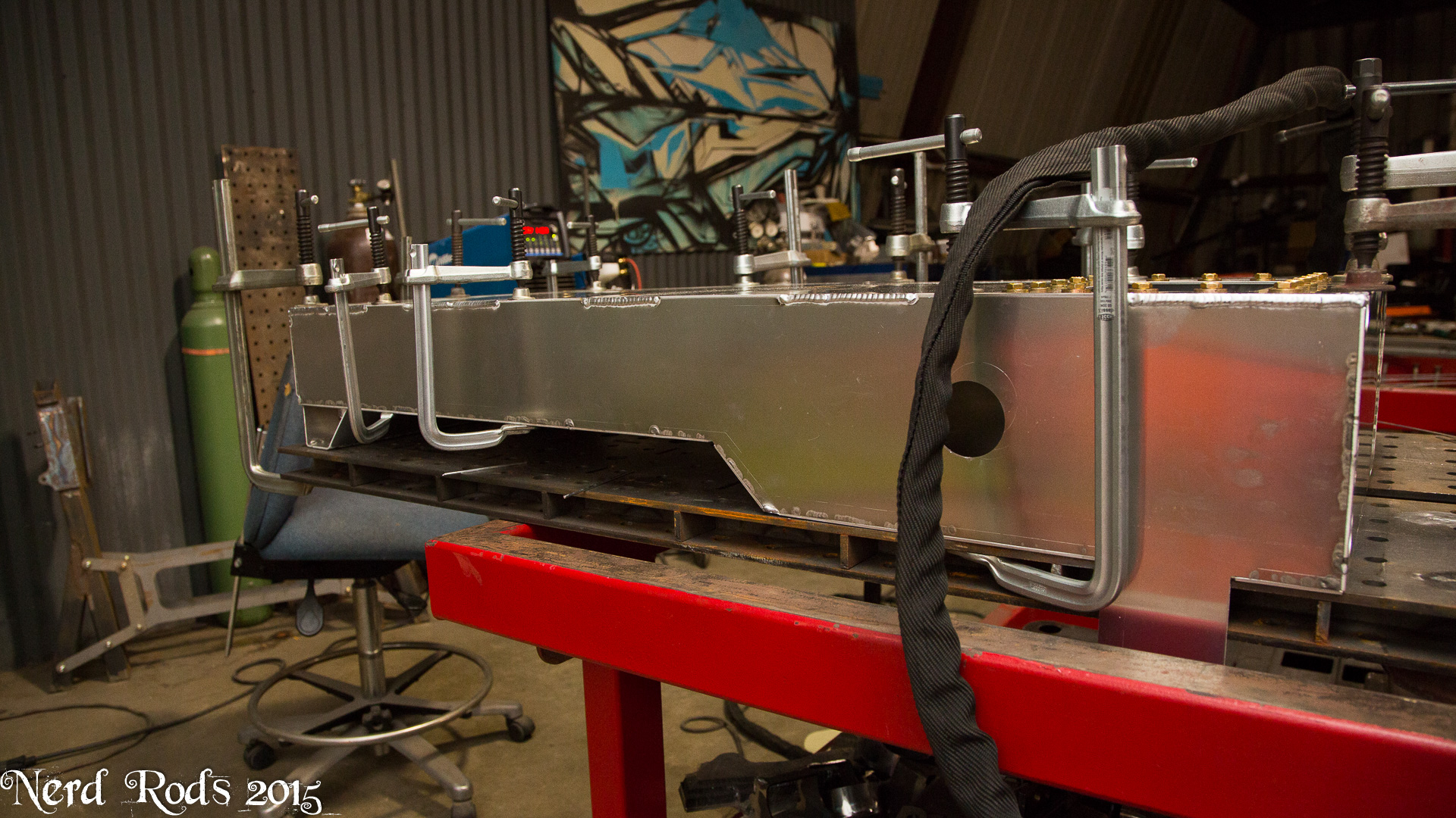
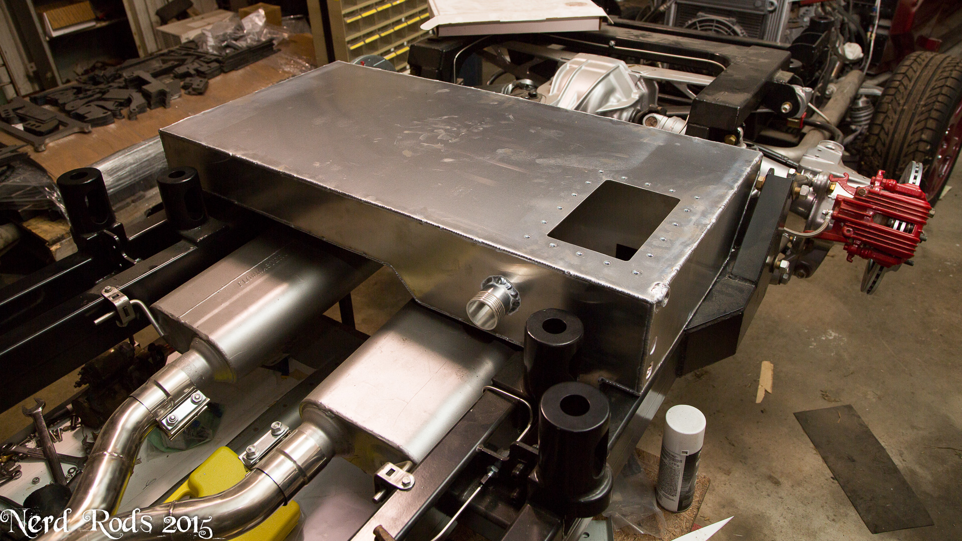
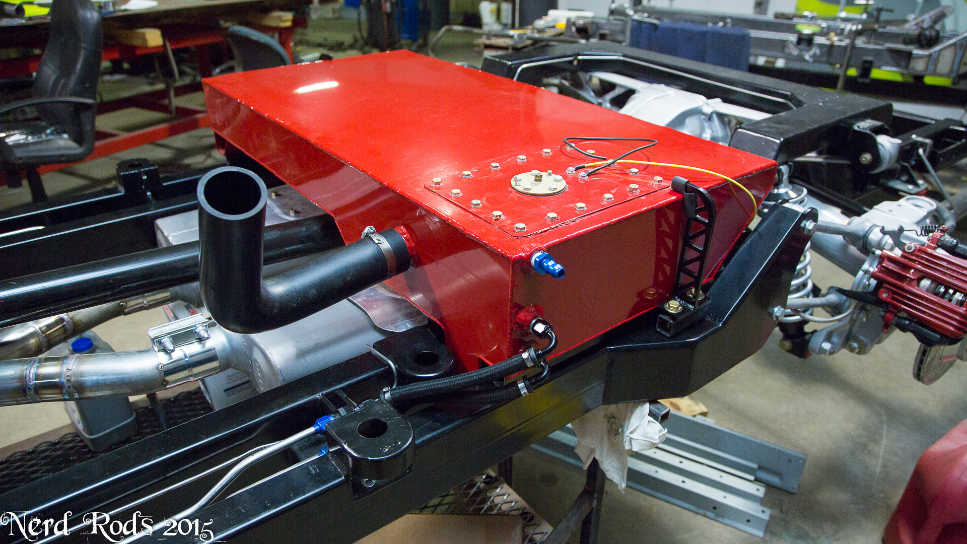
Some detailed photos of the tank assembly that were asked for by another guy but I thought everyone would like to see whats inside.
Gallery with all the photos so its easier to flip through them. I also omitted a few to make it under the posting limit so click here for the rest.
http://gallery.nerdrods.com/Customer...ake%20Webb/01/


[
 07-10-2015 | 01:26 PM
#111
Thread Starter
Launching!
Joined: Jan 2007
Posts: 294
Likes: 3
From: Luling TX In the Hot Rod Shop
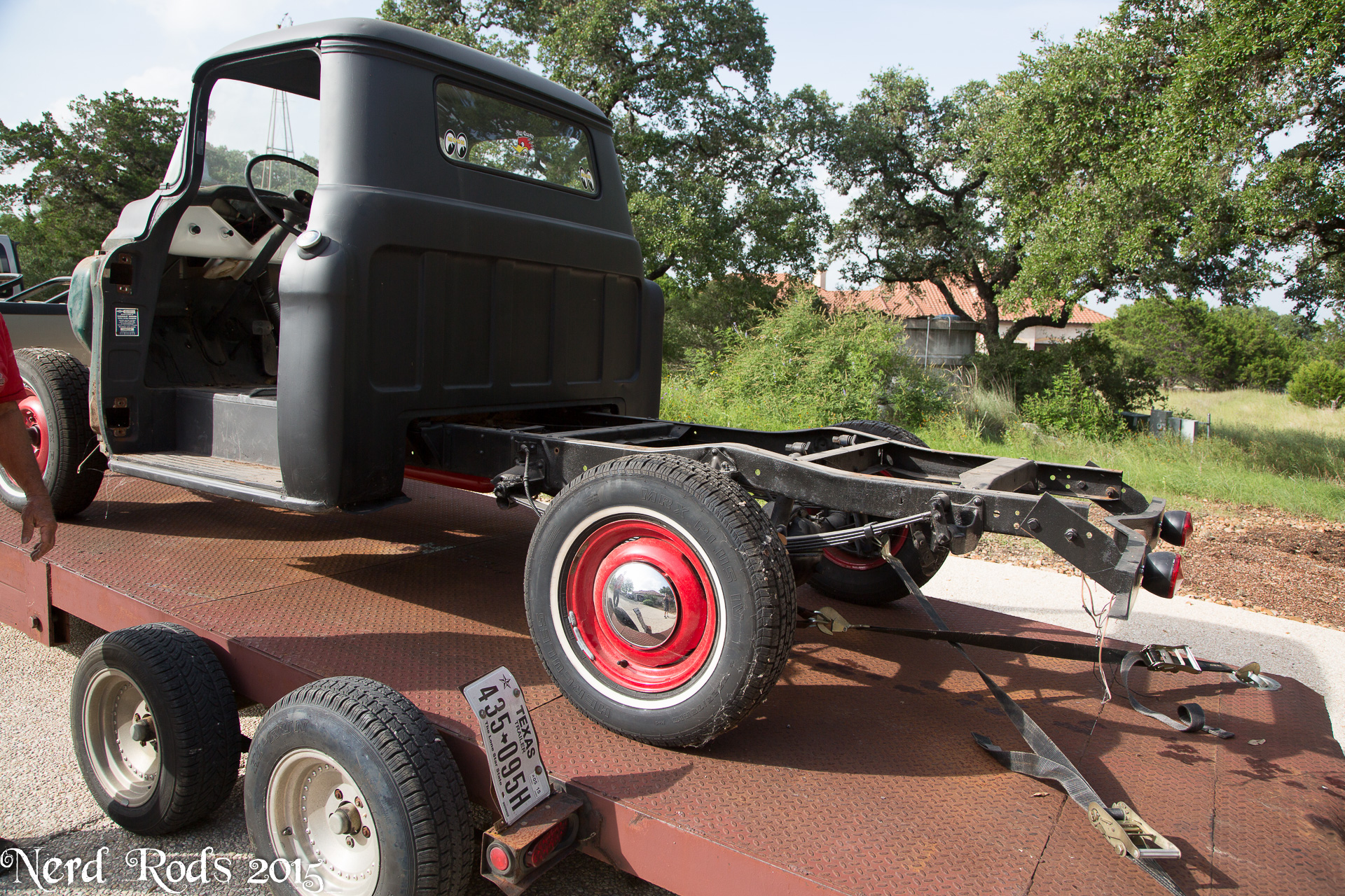
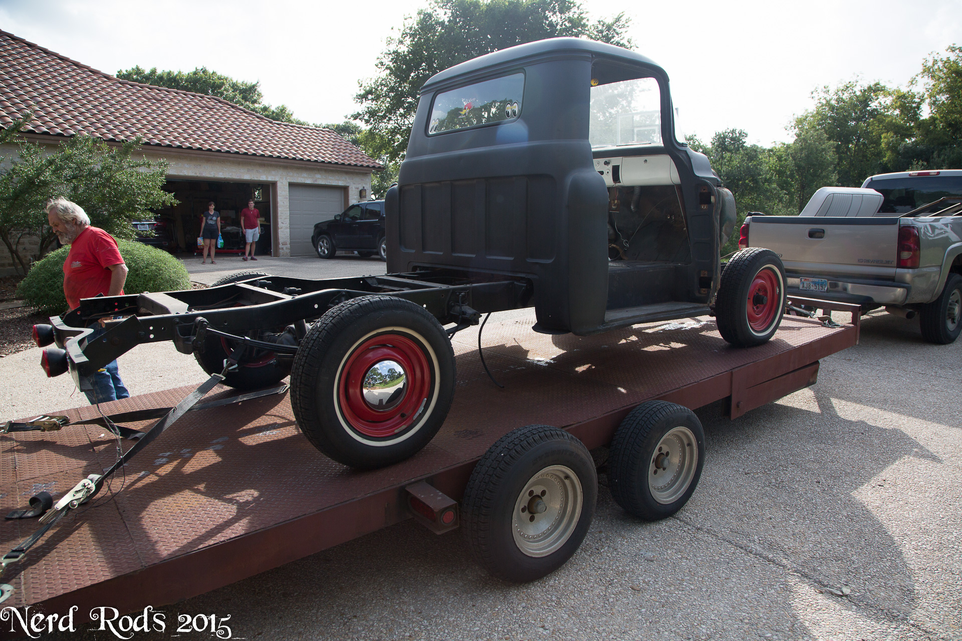
Georges truck is waiting on parts for the time being so we're working on the Webb's truck so the kid can drive it a bit before he takes off to collage in a few weeks. So its hammer time.
The complete photo gallery can be found here.
http://gallery.nerdrods.com/Customer...ake%20Webb/02/
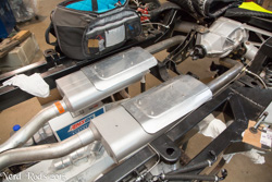
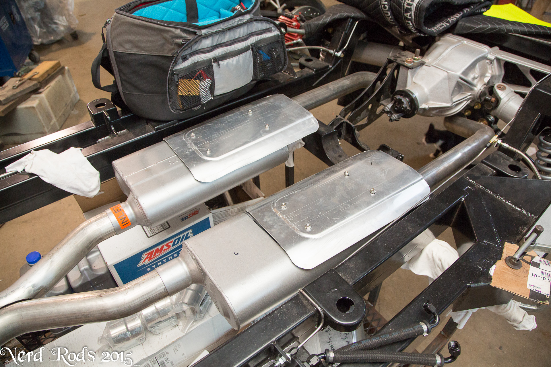
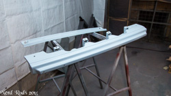
Got the heat shields done for the mufflers.
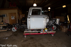
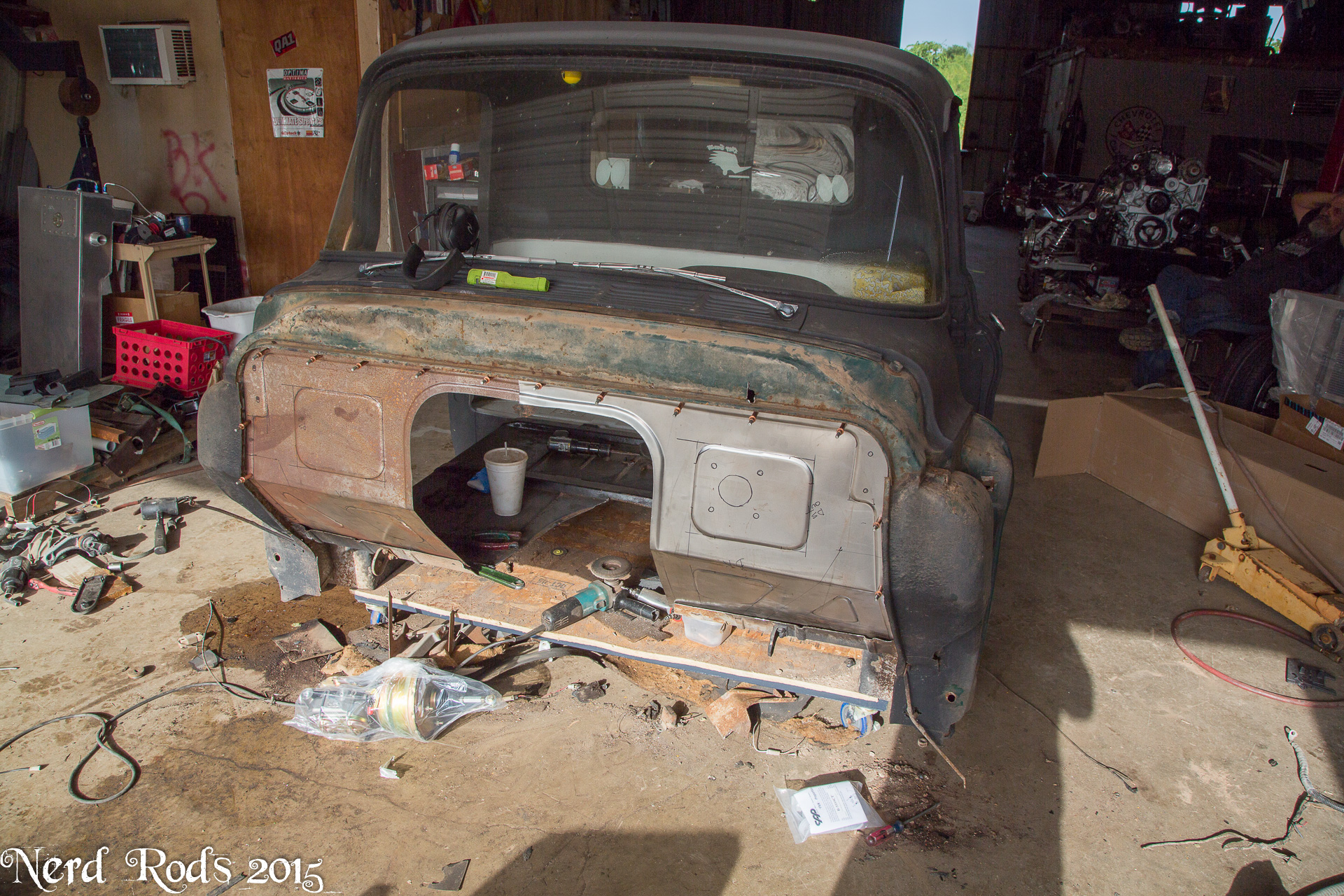
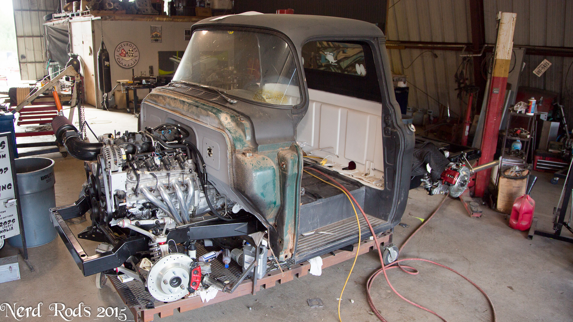
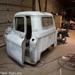
And picked up their cab.

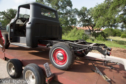
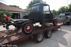
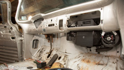
Got it back to the shop Monday night and by Wednesday afternoon it looked like this.
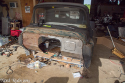
The firewall and floor will be done this afternoon. We're going to do this truck 1" taller than the lowest possible so the ribs in the floor can be left alone and they can use the bench seat.
Later
-Russell @ Nerd Rods
The complete photo gallery can be found here.
http://gallery.nerdrods.com/Customer...ake%20Webb/02/
Got the heat shields done for the mufflers.
And picked up their cab.
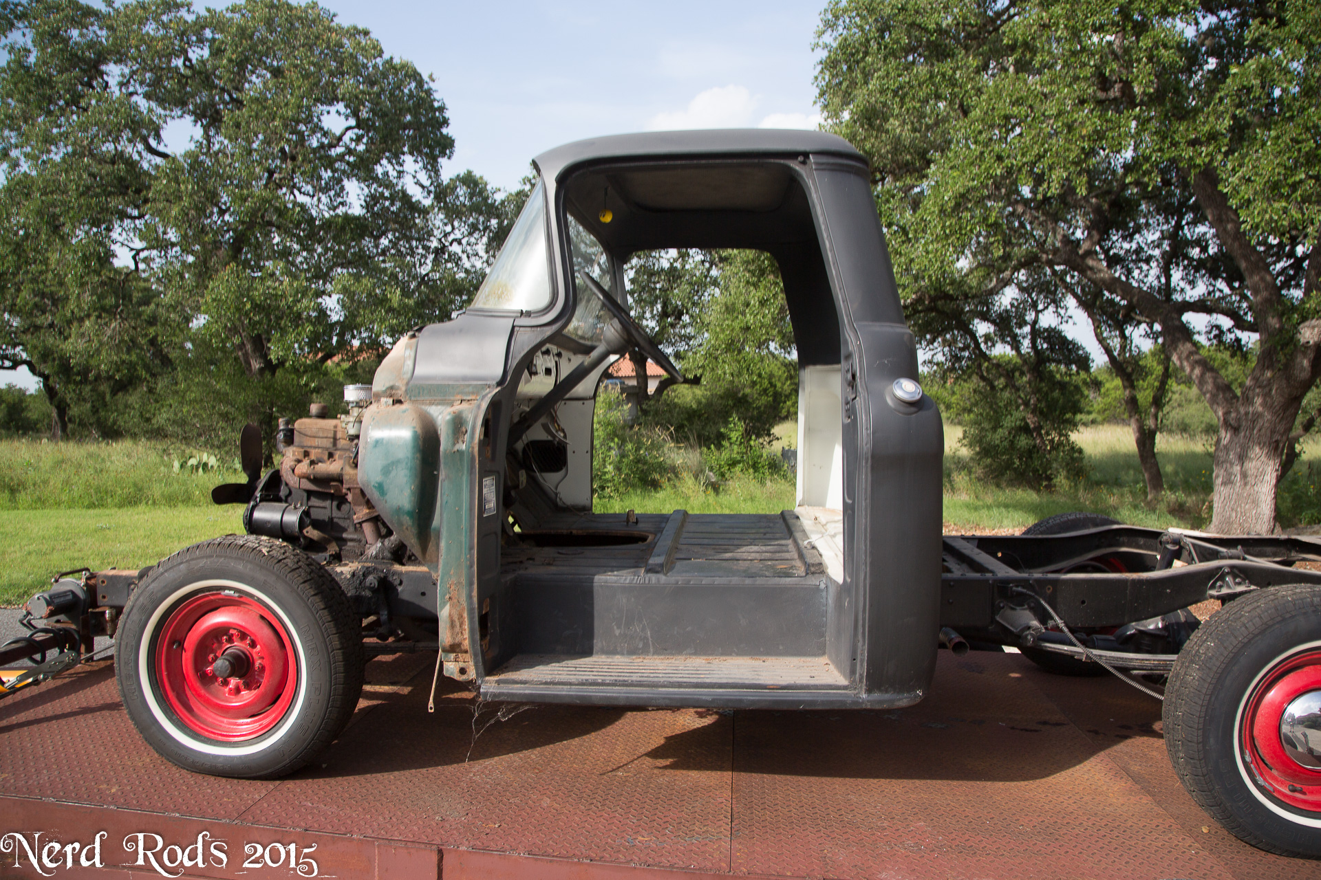
Got it back to the shop Monday night and by Wednesday afternoon it looked like this.
The firewall and floor will be done this afternoon. We're going to do this truck 1" taller than the lowest possible so the ribs in the floor can be left alone and they can use the bench seat.
Later
-Russell @ Nerd Rods
07-20-2015 | 07:24 PM
#112
Thread Starter
Launching!
Joined: Jan 2007
Posts: 294
Likes: 3
From: Luling TX In the Hot Rod Shop
Lots going on with both Georges truck and the Webb's
On the Webb's
Got the engine fired up to check for leaks in the transmission cooler and fuel lines.

Short video of here running for the customers
https://ls1tech.com/forums/wODnGeehUvg
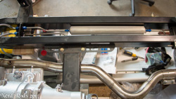
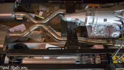
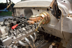
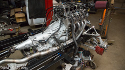
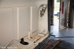
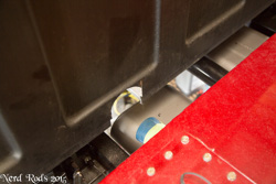
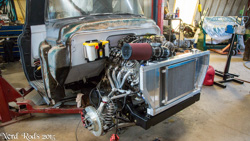
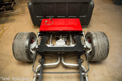
Then I realized it was a mess and clean it up a bit for some nicer photos. You can see the tank hold downs and exhaust heat shields. Here I screwed up and didn't leave enough room for the heat shields and had to add a spacer to the tank to move it up to clear. I'll correct this in future designs by wrapping the mufflers and moving the exhaust down a little bit.


And we got the body on for the last time.


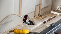
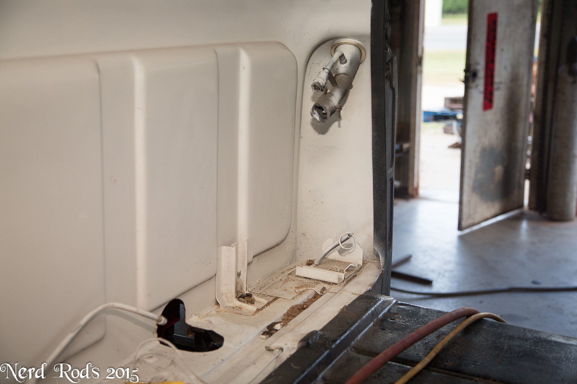
We had to do a little different floor board modification for the gas tank filler neck since we raised the tank a bit but it won't be hard to seal up.
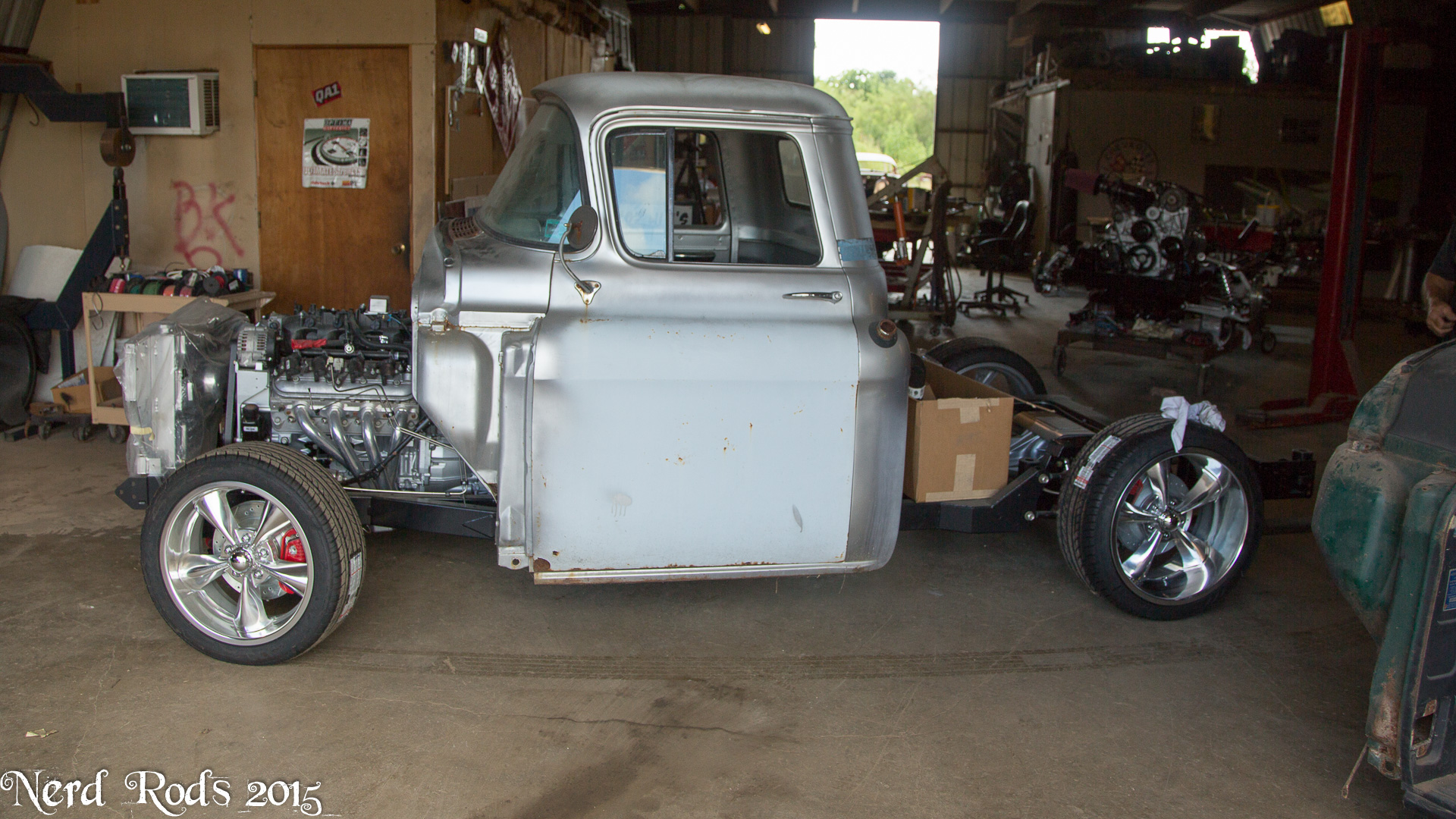
We also finally got the wheels for George's truck and got it on the ground to take a look at.


We're waiting on the paint booth to take Georges truck over for paint then we can do final assembly.
Later
-Russell @ Nerd Rods
On the Webb's
Got the engine fired up to check for leaks in the transmission cooler and fuel lines.
Short video of here running for the customers
https://ls1tech.com/forums/wODnGeehUvg
Then I realized it was a mess and clean it up a bit for some nicer photos. You can see the tank hold downs and exhaust heat shields. Here I screwed up and didn't leave enough room for the heat shields and had to add a spacer to the tank to move it up to clear. I'll correct this in future designs by wrapping the mufflers and moving the exhaust down a little bit.
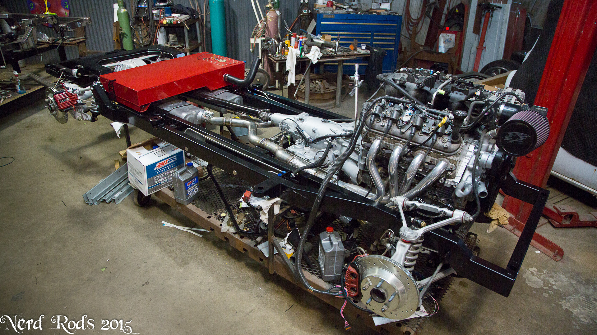

And we got the body on for the last time.
We had to do a little different floor board modification for the gas tank filler neck since we raised the tank a bit but it won't be hard to seal up.


We also finally got the wheels for George's truck and got it on the ground to take a look at.


We're waiting on the paint booth to take Georges truck over for paint then we can do final assembly.
Later
-Russell @ Nerd Rods
07-25-2015 | 06:10 PM
#113
Thread Starter
Launching!
Joined: Jan 2007
Posts: 294
Likes: 3
From: Luling TX In the Hot Rod Shop
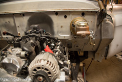
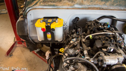
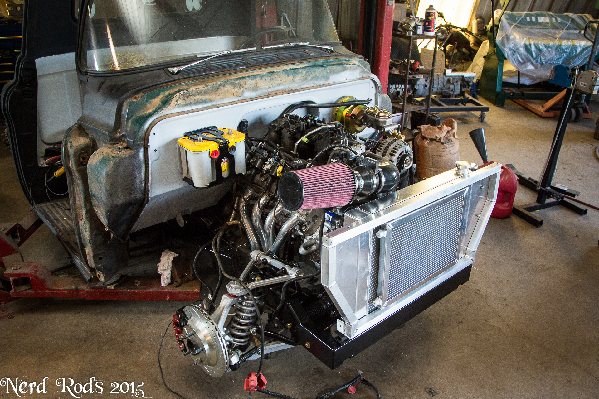
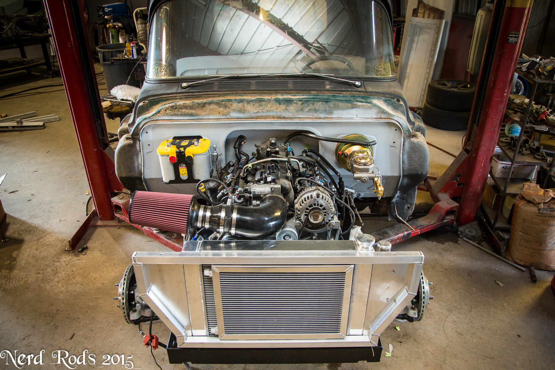
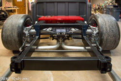
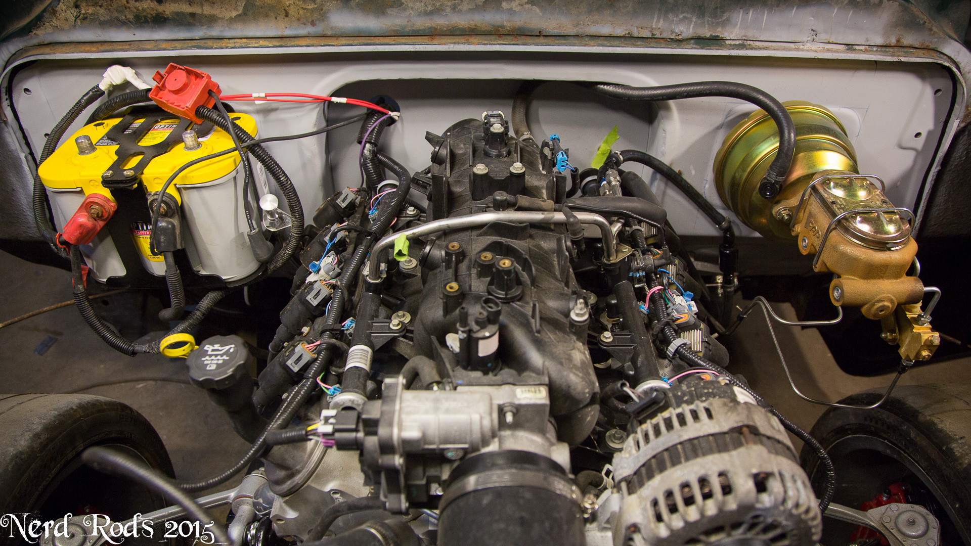
Battery mounted with an SKFab battery box and some bolts welded to the back of it so we could mount it to the firewall.
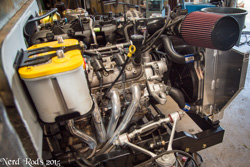
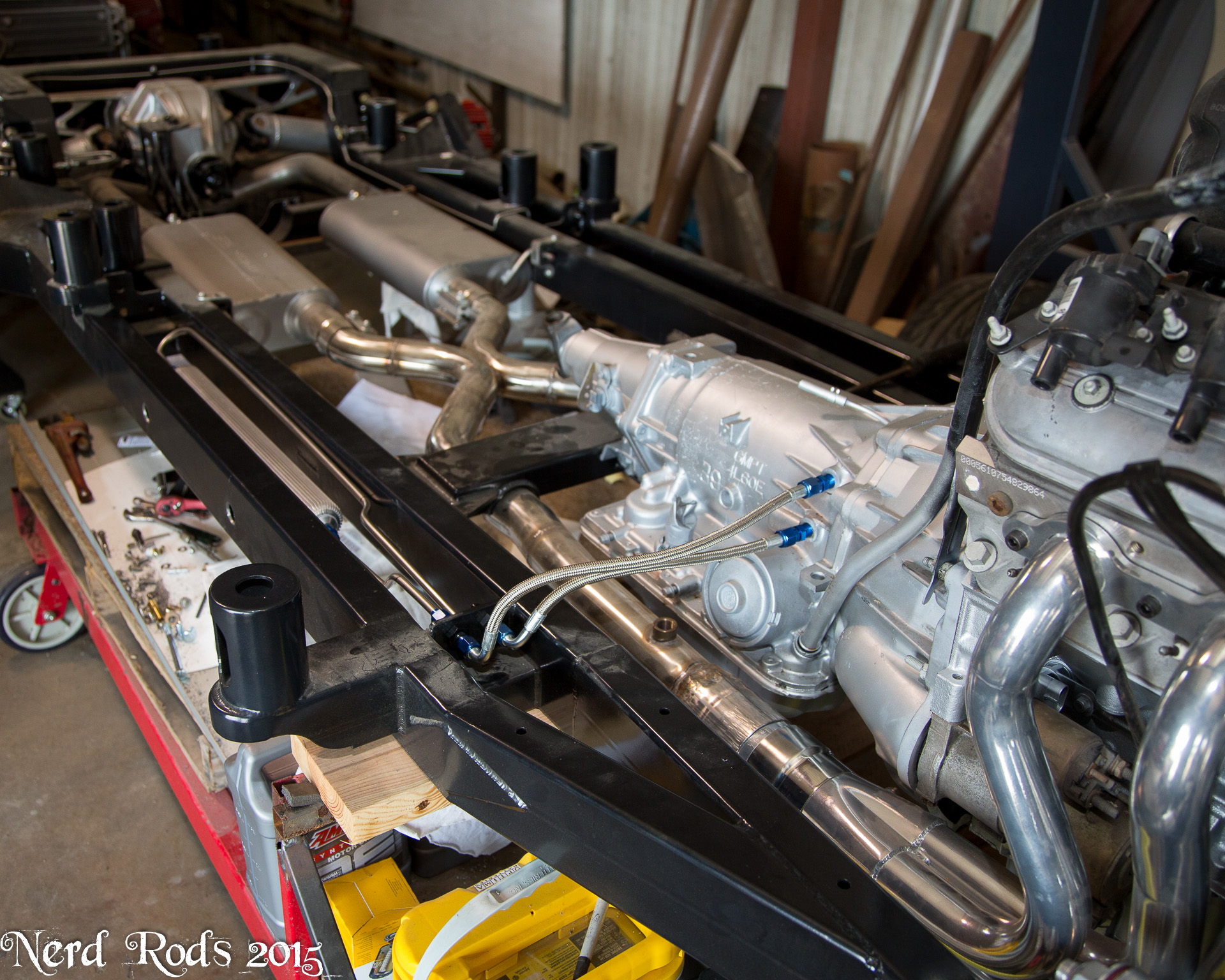
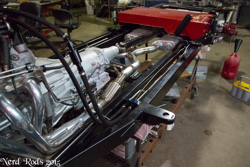
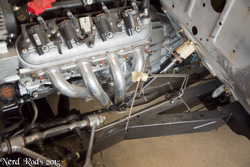
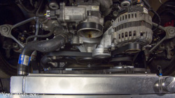
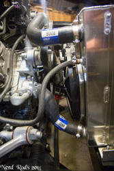
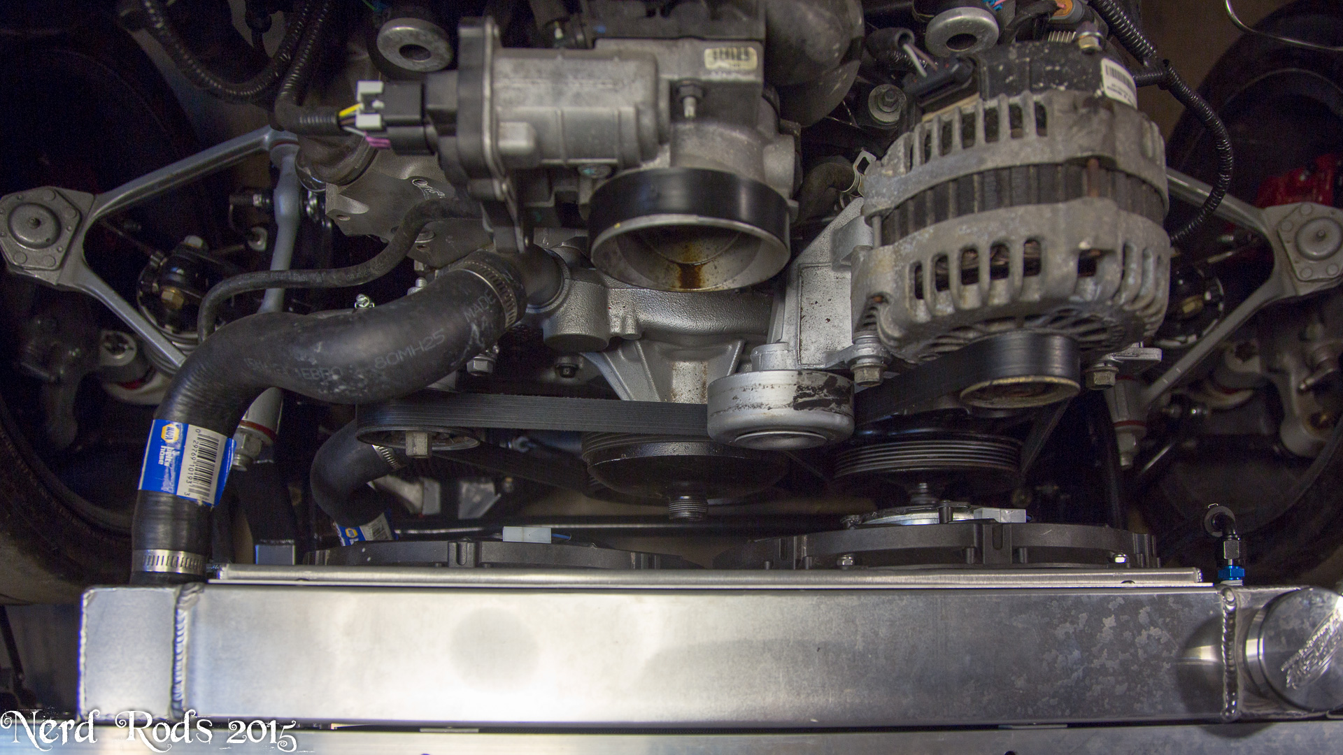
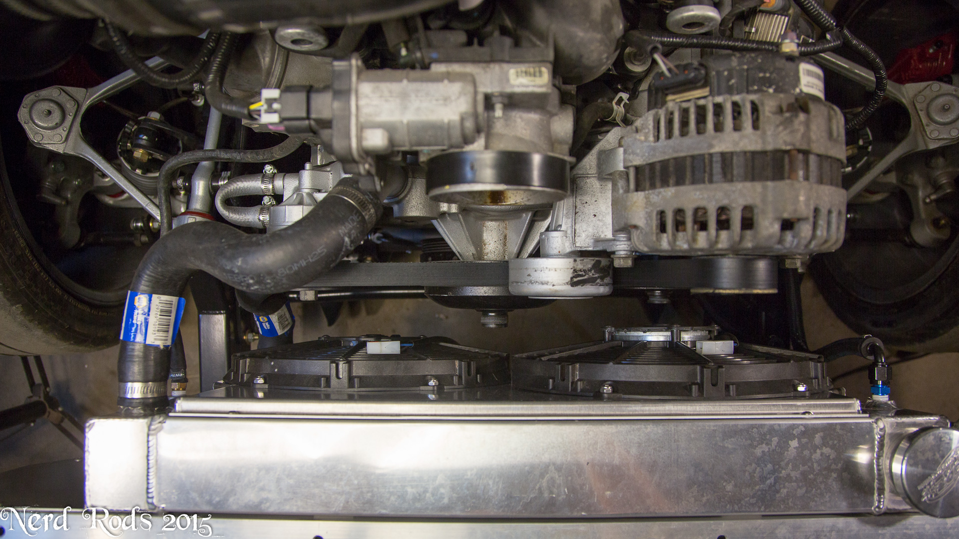
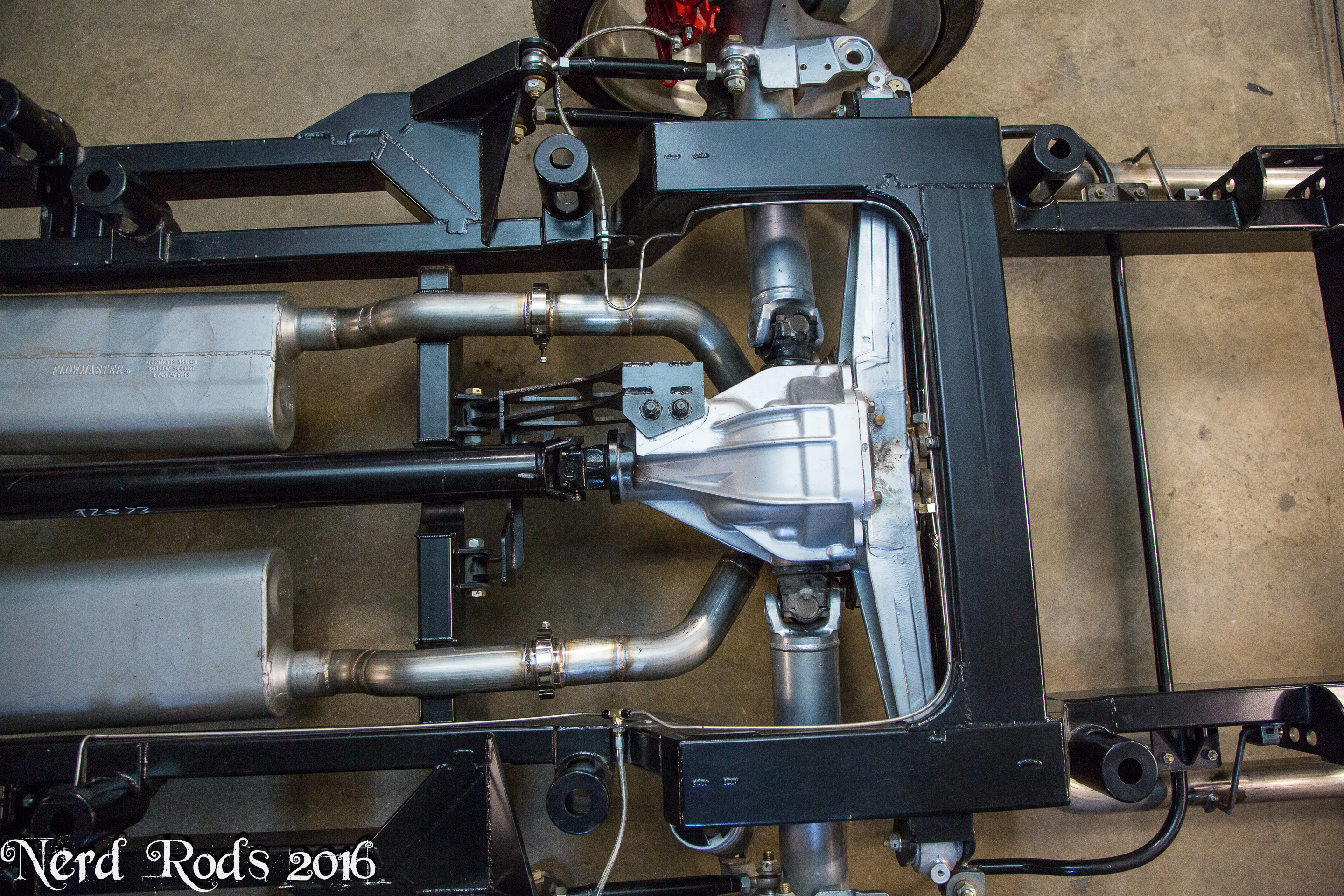
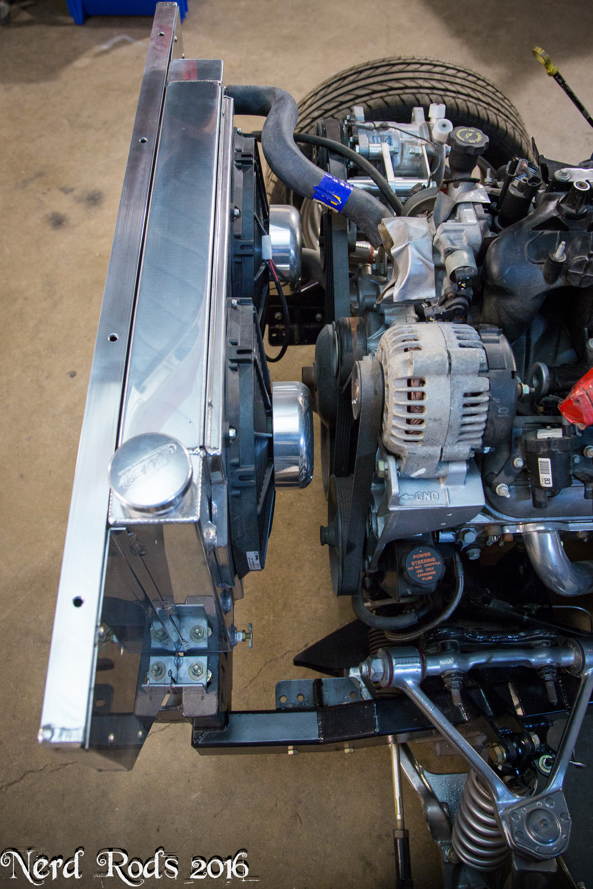
Power steering lines are done and you can see we're using the auto transmission cooler for a rack and pinion cooler. I went in the bottom and out the top to keep it from all back flowing into the overflow tank since its under the top line and cut down on the length of line. I also told the customer if I'm crazy and there is a problem I'll install another cooler and different lines on my dime later. The column shifter cable is installed and tuned.
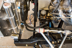
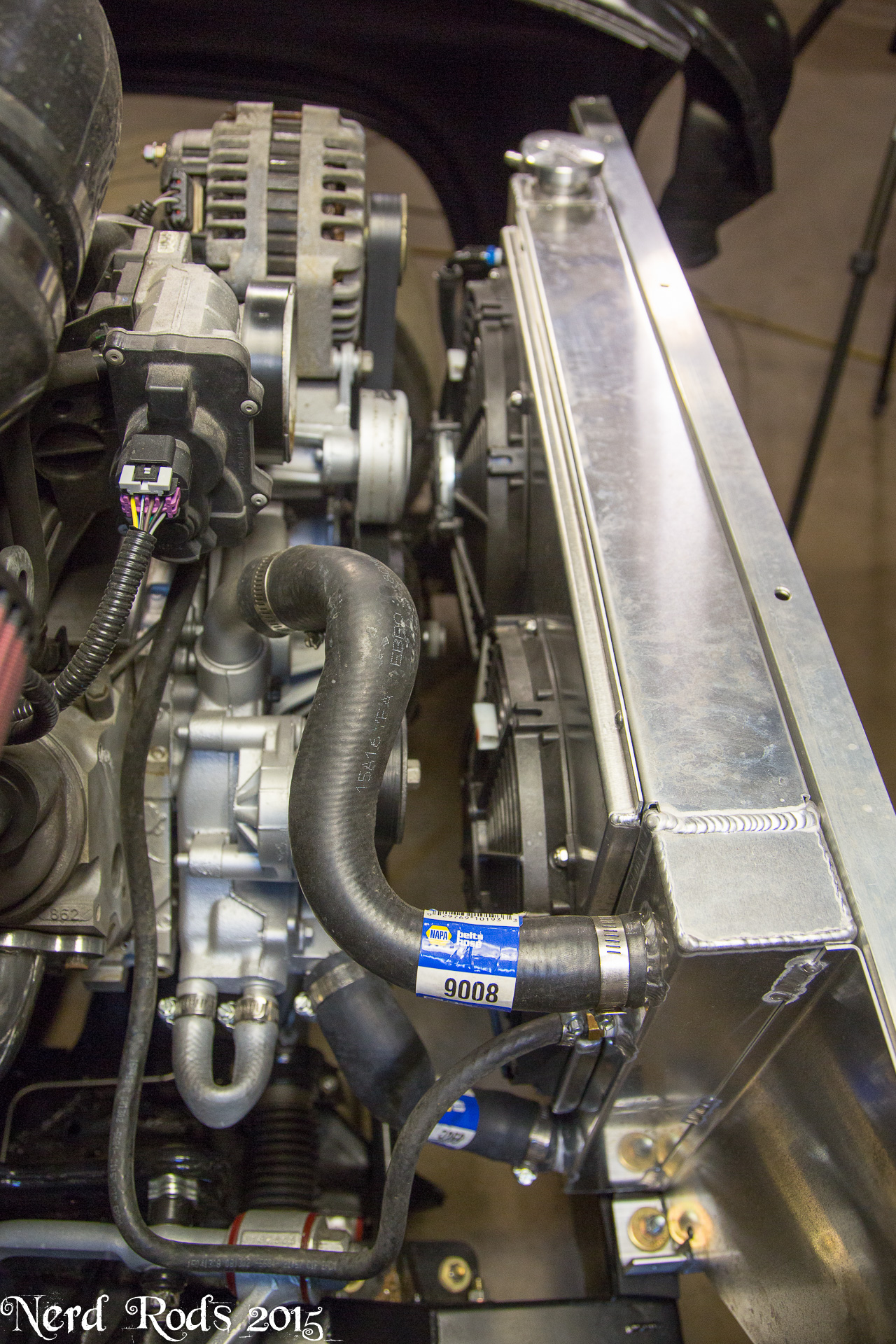
And the PRC Radiator System is installed for the final time and getting hooked up. We're going to use the radiator temp gauge hole for the steam vent line off the throttle body.

Later
-Russell @ Nerd Rods
07-30-2015 | 05:18 AM
#114
Thread Starter
Launching!
Joined: Jan 2007
Posts: 294
Likes: 3
From: Luling TX In the Hot Rod Shop
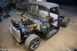
She moves under her own power now.
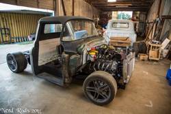

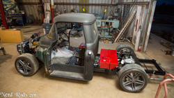
Photo gallery for easy viewing and a few more photos not posted here.
http://gallery.nerdrods.com/Customers/CP5559C4/0002- Rick Jake Webb/03/
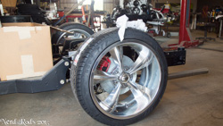
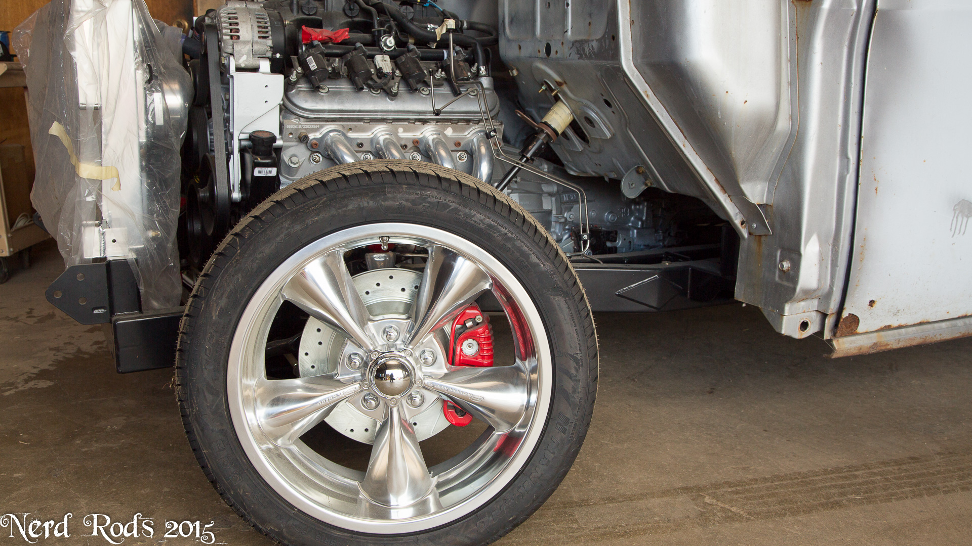
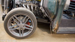
Rick and Jake are waiting on their custom offset 20's to be done so I'm lending them my old race wheels and tires. I'm not using them at the moment.
BEFORE YOU ASK ABOUT THE REAR TIRES
Yes 345's will fit but not with stock fenders. I just needed a set of tires that were very even and equal for balancing and alignment and this was the only set not in use at the moment.
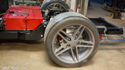
But the 275 fronts will work on a 10.5" wheel with 56mm offset and a small spacer so it won't hit the sway bar.
The filler neck worked perfectly but I need to re seal the gas tank. I think someone used the wrong sealer on the lids and she bleeds when hit with direct sun. So I'll have that sorted shortly.
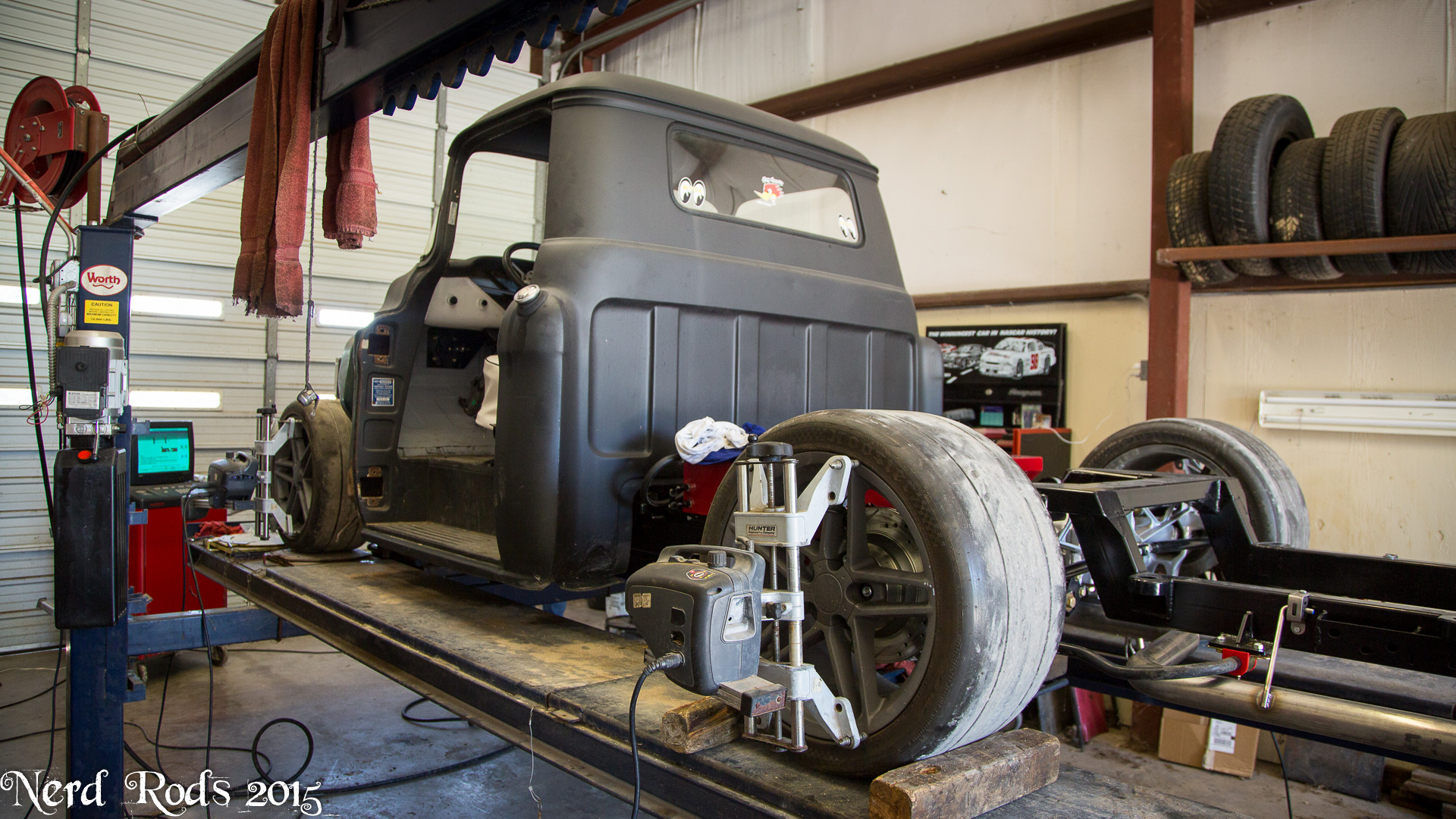
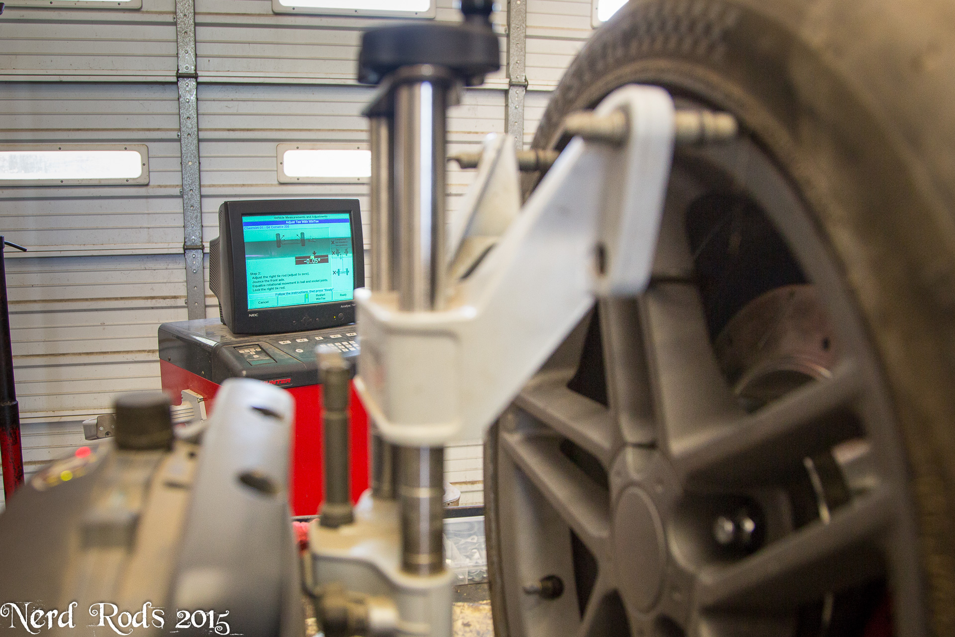
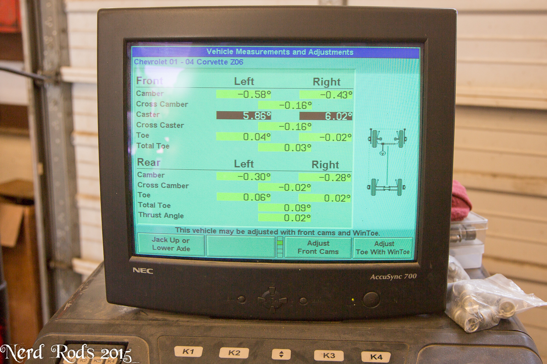
The alignment is also mostly sorted. I ran out of time and this was close enough so we can start balancing and adding body work. Alignment is hard once the fenders are covering the wheels and fining an alignment machine that can do them is a royal pain so we align like this first. I didn't realize that this older alignment machine would allow us to put the scales under the wheels or I would have brought them too. Next time for sure now that I know about this guy just up the road from me.
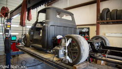

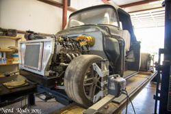


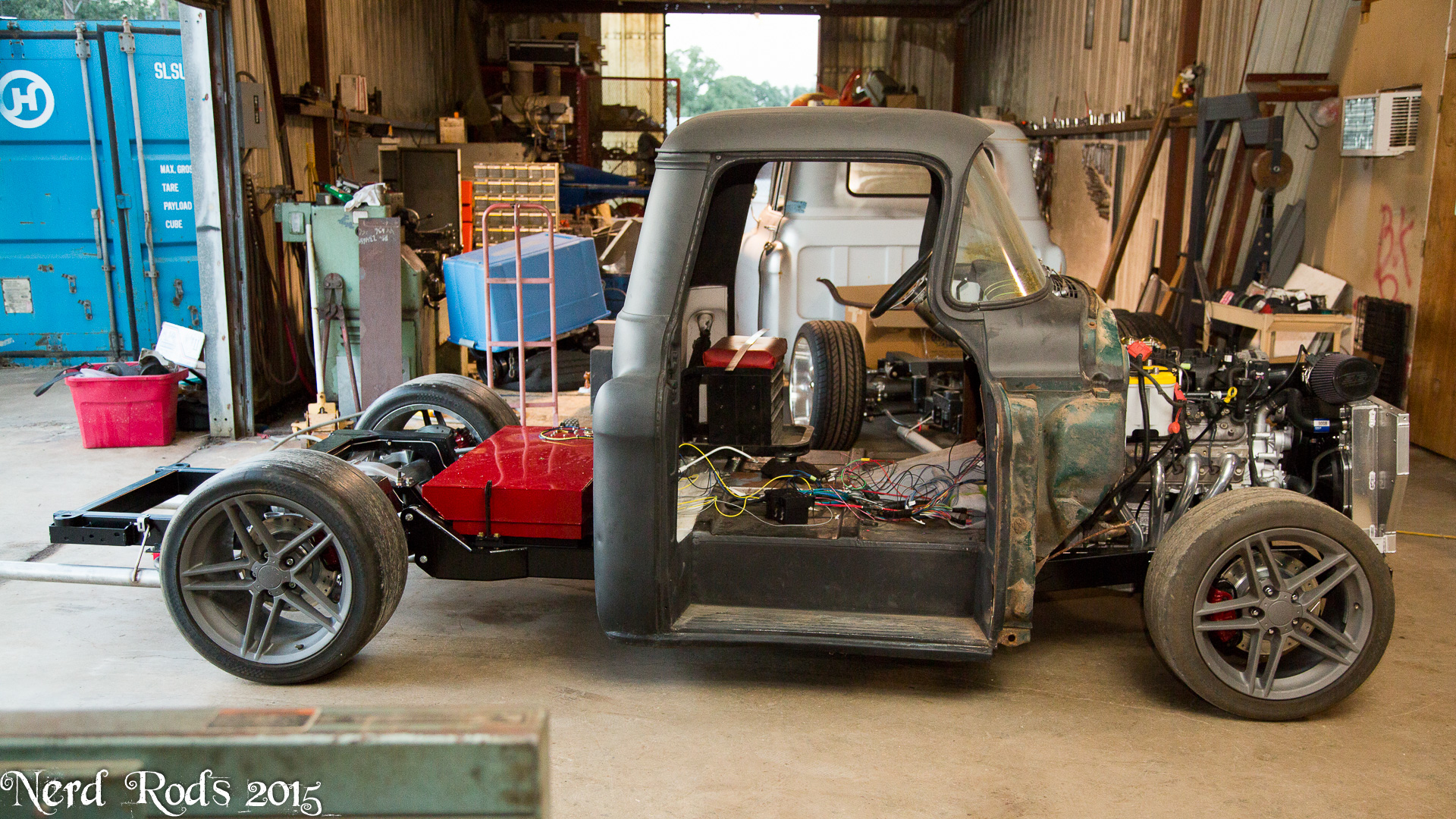

Photo gallery for easy viewing and a few more photos not posted here.
http://gallery.nerdrods.com/Customers/CP5559C4/0002- Rick Jake Webb/03/
Rick and Jake are waiting on their custom offset 20's to be done so I'm lending them my old race wheels and tires. I'm not using them at the moment.
BEFORE YOU ASK ABOUT THE REAR TIRES
Yes 345's will fit but not with stock fenders. I just needed a set of tires that were very even and equal for balancing and alignment and this was the only set not in use at the moment.


But the 275 fronts will work on a 10.5" wheel with 56mm offset and a small spacer so it won't hit the sway bar.


The filler neck worked perfectly but I need to re seal the gas tank. I think someone used the wrong sealer on the lids and she bleeds when hit with direct sun. So I'll have that sorted shortly.
The alignment is also mostly sorted. I ran out of time and this was close enough so we can start balancing and adding body work. Alignment is hard once the fenders are covering the wheels and fining an alignment machine that can do them is a royal pain so we align like this first. I didn't realize that this older alignment machine would allow us to put the scales under the wheels or I would have brought them too. Next time for sure now that I know about this guy just up the road from me.
 08-12-2015 | 02:46 AM
#115
Thread Starter
Launching!
Joined: Jan 2007
Posts: 294
Likes: 3
From: Luling TX In the Hot Rod Shop
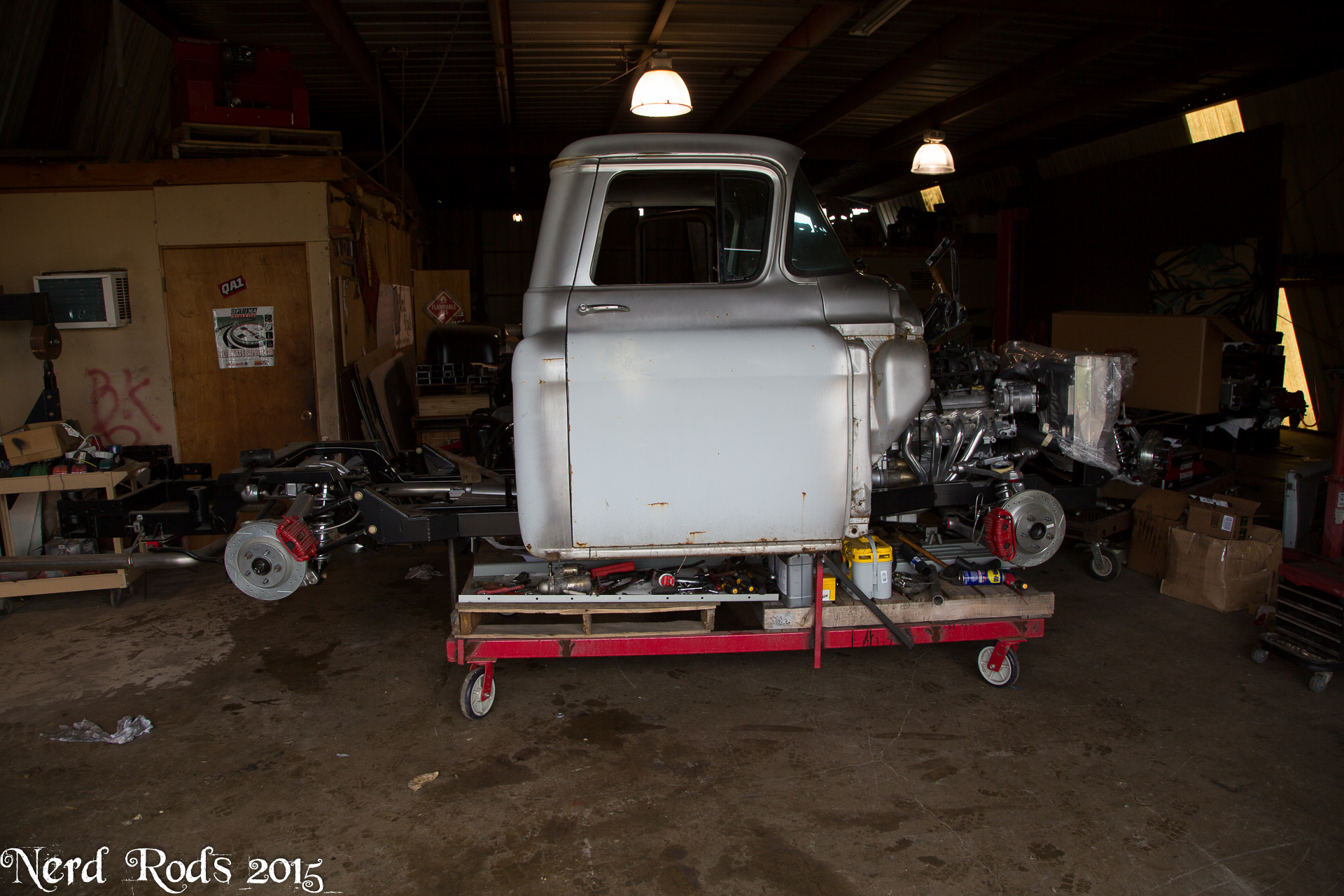
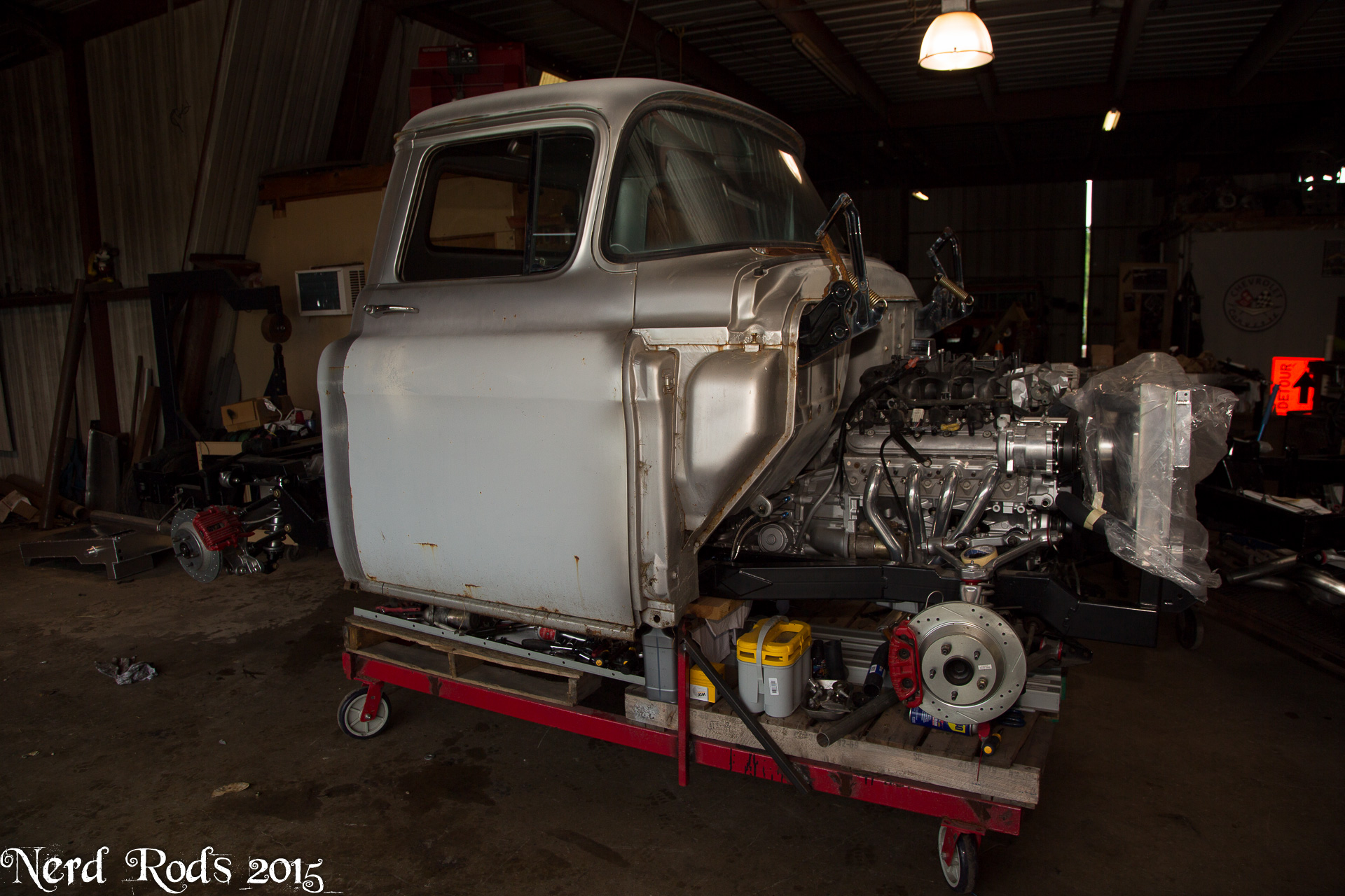
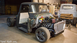
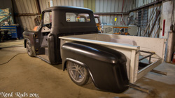
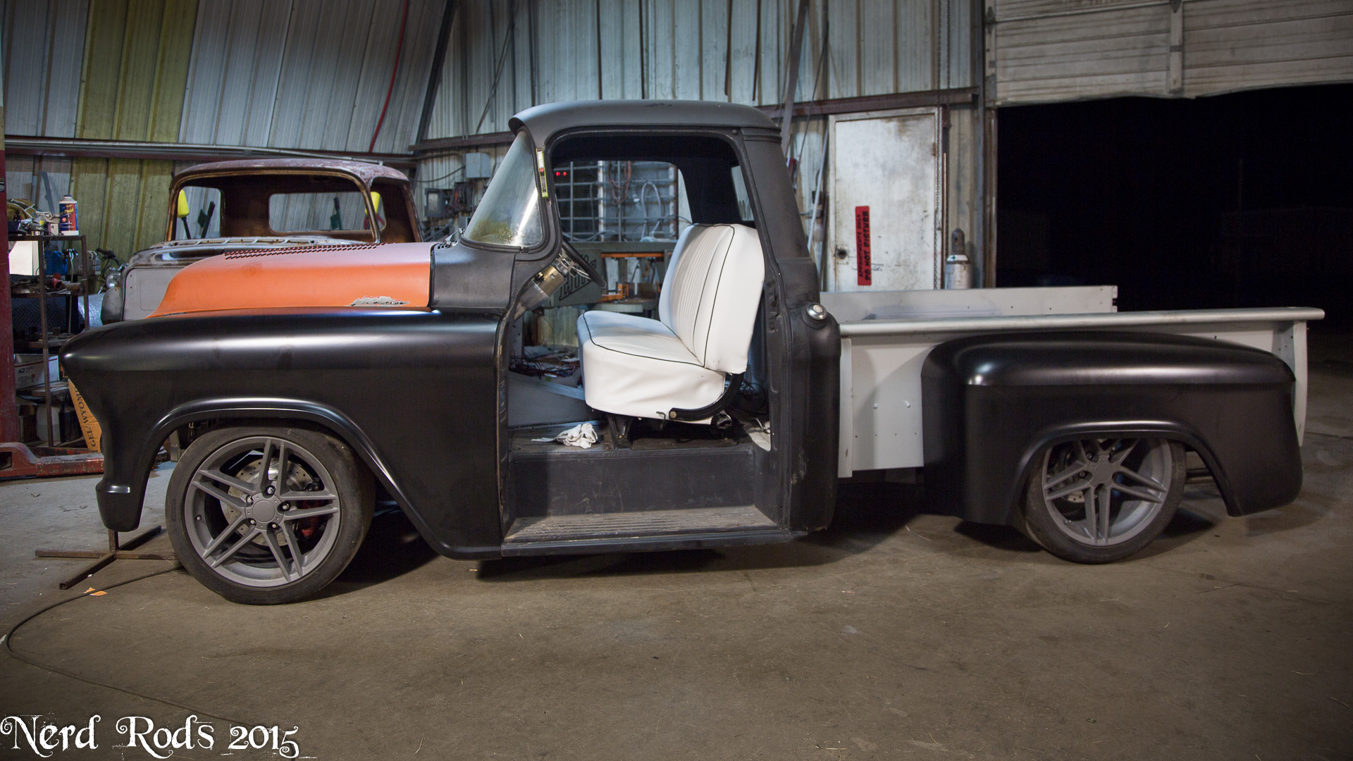
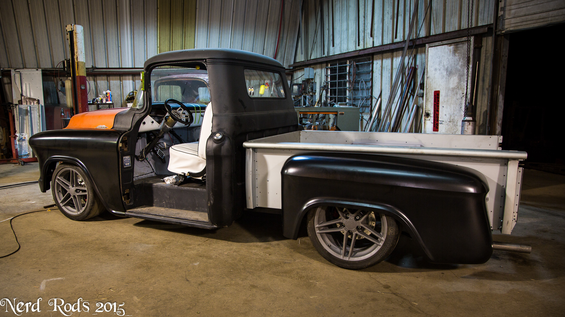
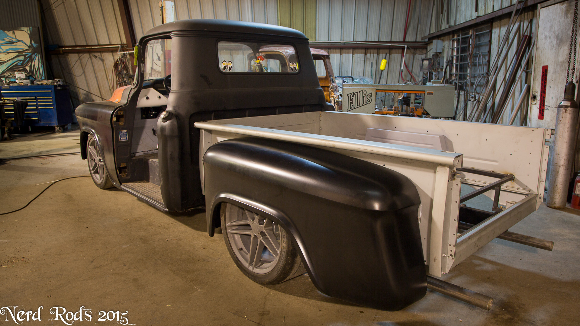
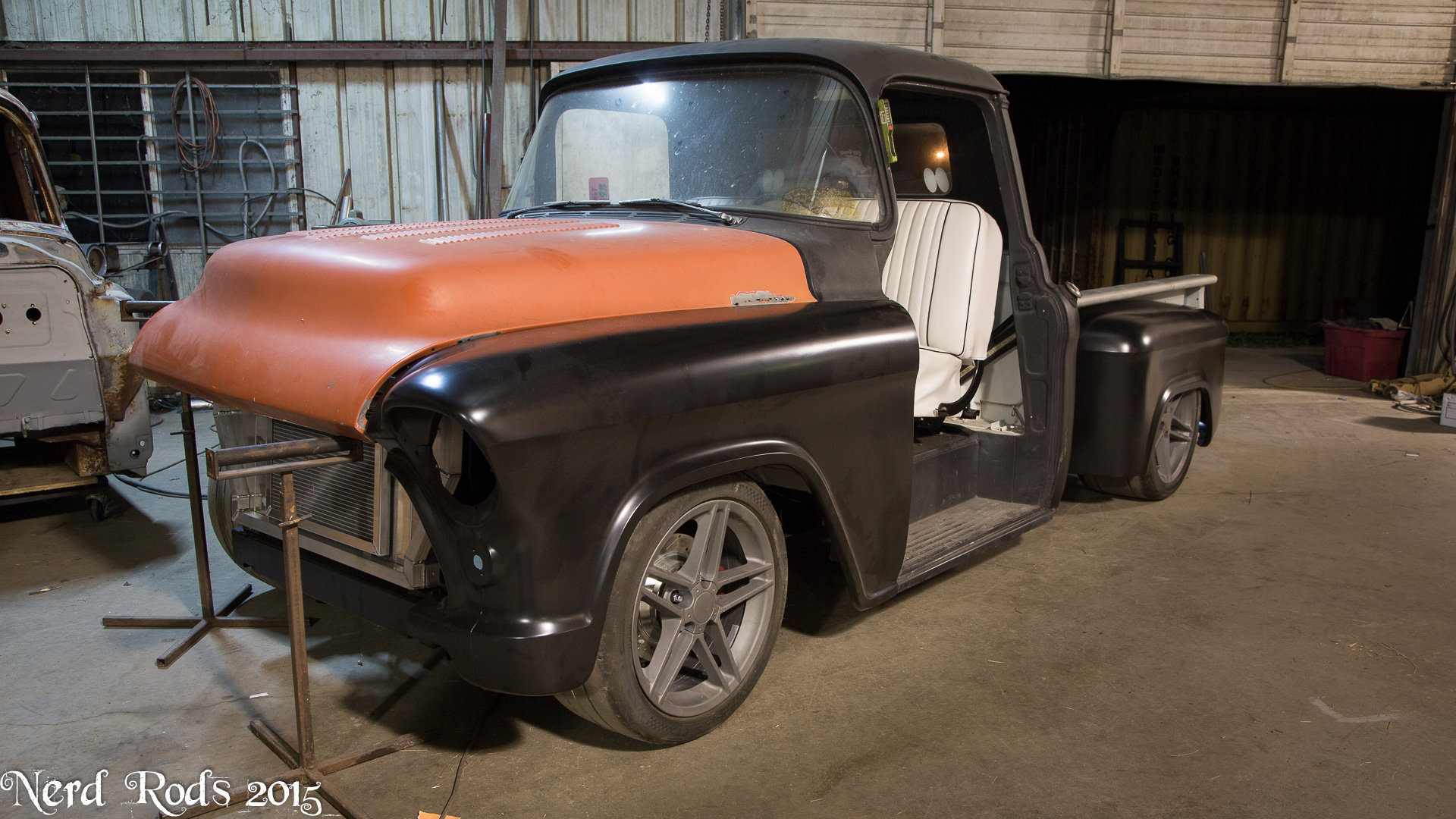
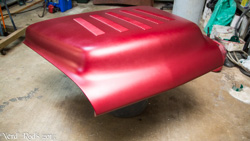
We with this guy about ready to leave we all really wanted to see what the stance was going to look like so we slapped on a pair fenders and balanced a hood up top. Mmmmmmm, what a good stance. And this is still 1 inch higher than the maximum low you can do with our frame. We will do the lowest possible we can with my fathers truck so be ready. Also I shot these photos from waist high. It makes for a good photo but in person it looks even lower. I also shot a bunch of video to help explain whats involved with doing the low body stance for guys interested in seeing a bit more. I'm editing it right now and hope to have it up before the end of the week.
The easy flip through gallery is here ( http://gallery.nerdrods.com/Customer...ake%20Webb/03/ )
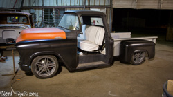


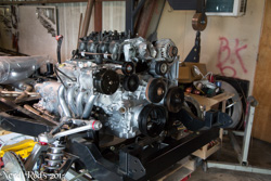
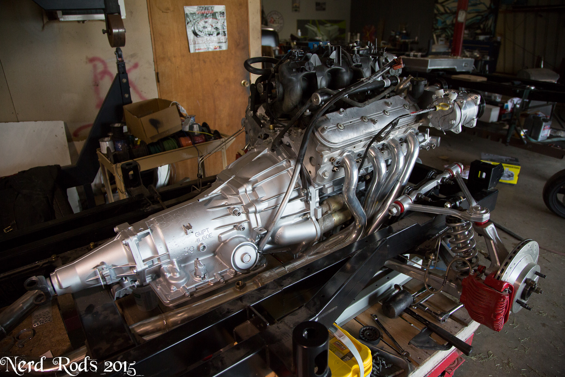
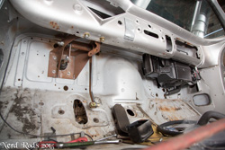
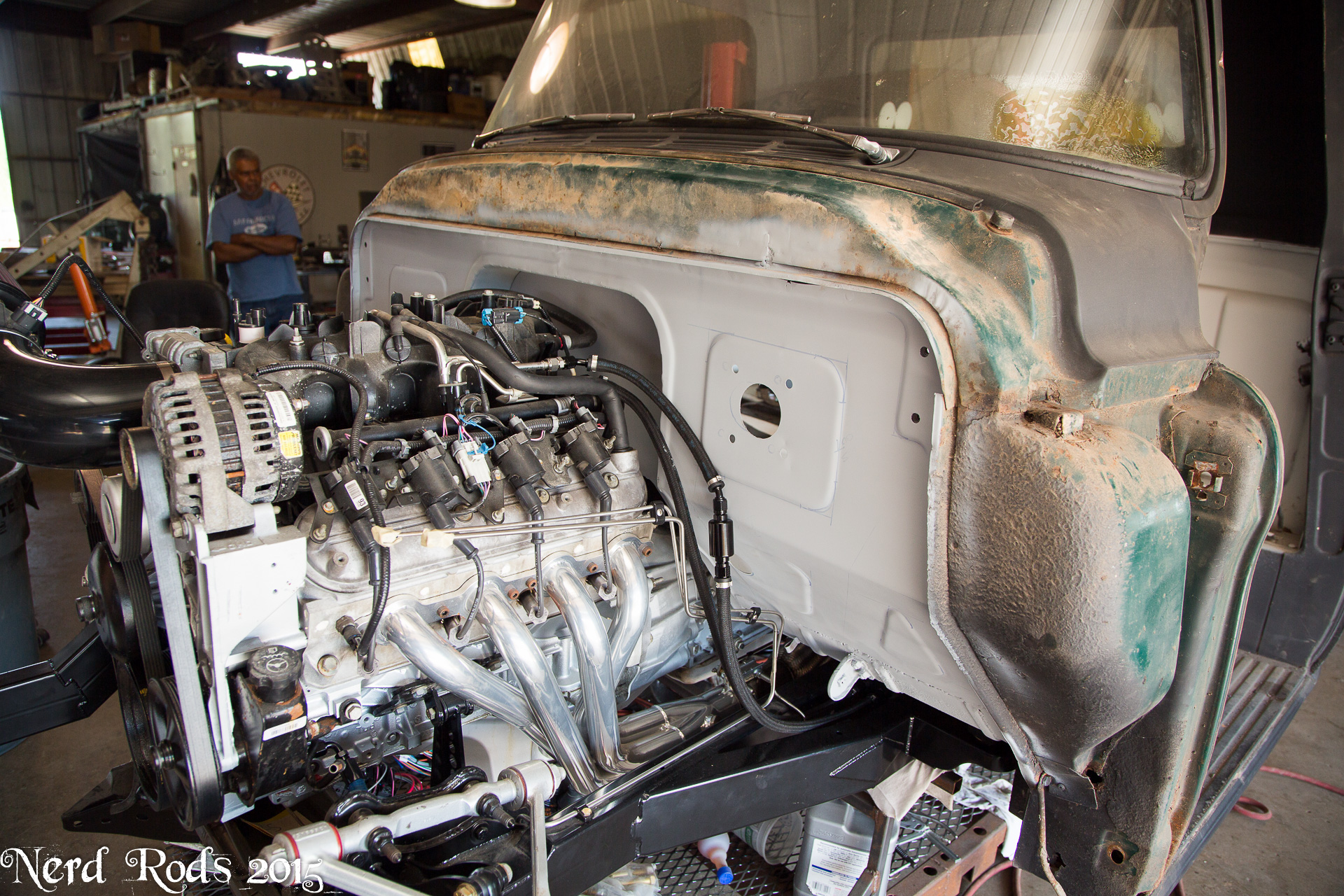
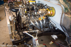
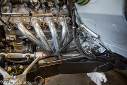
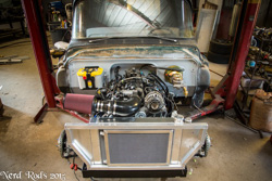
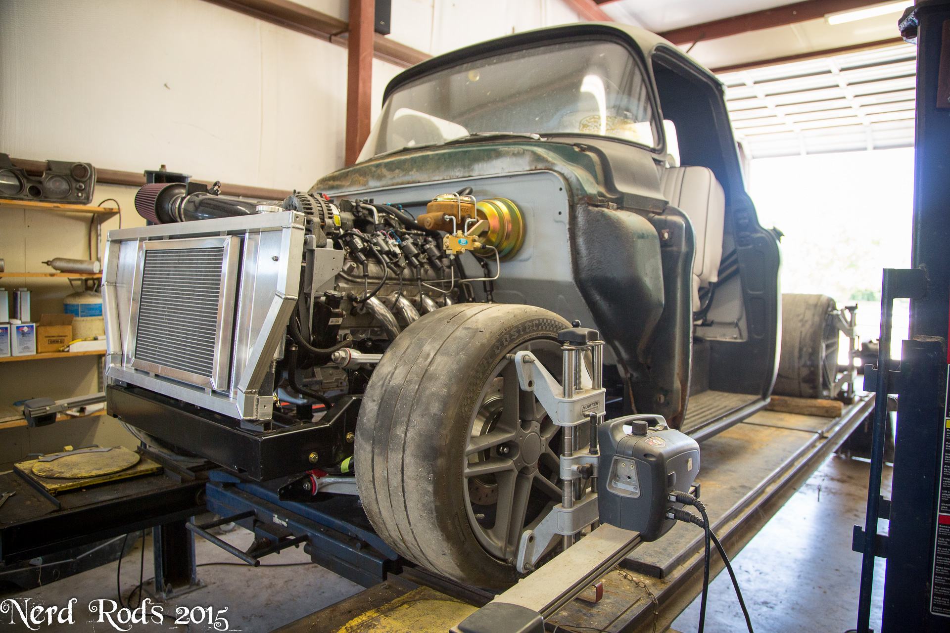
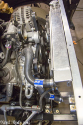
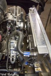
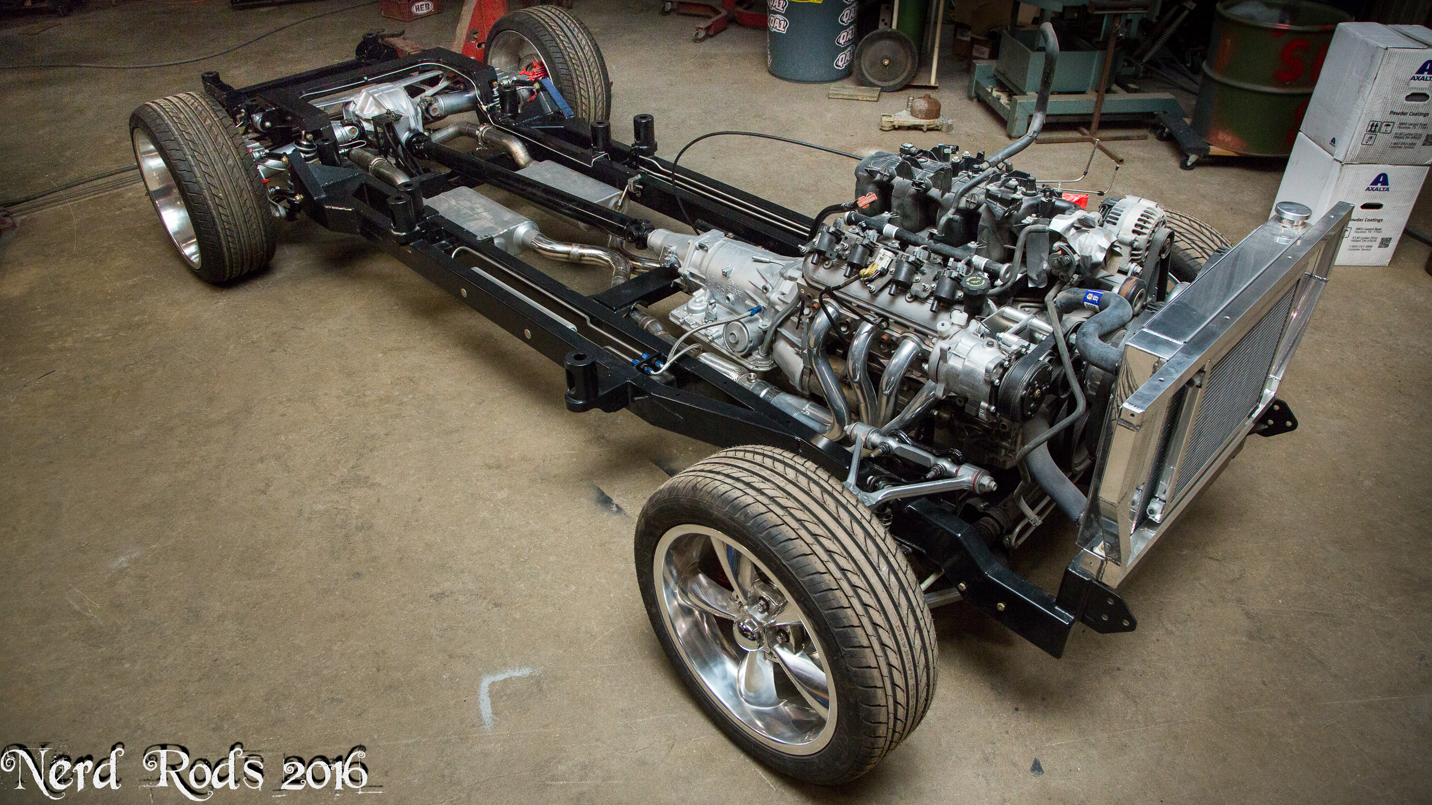
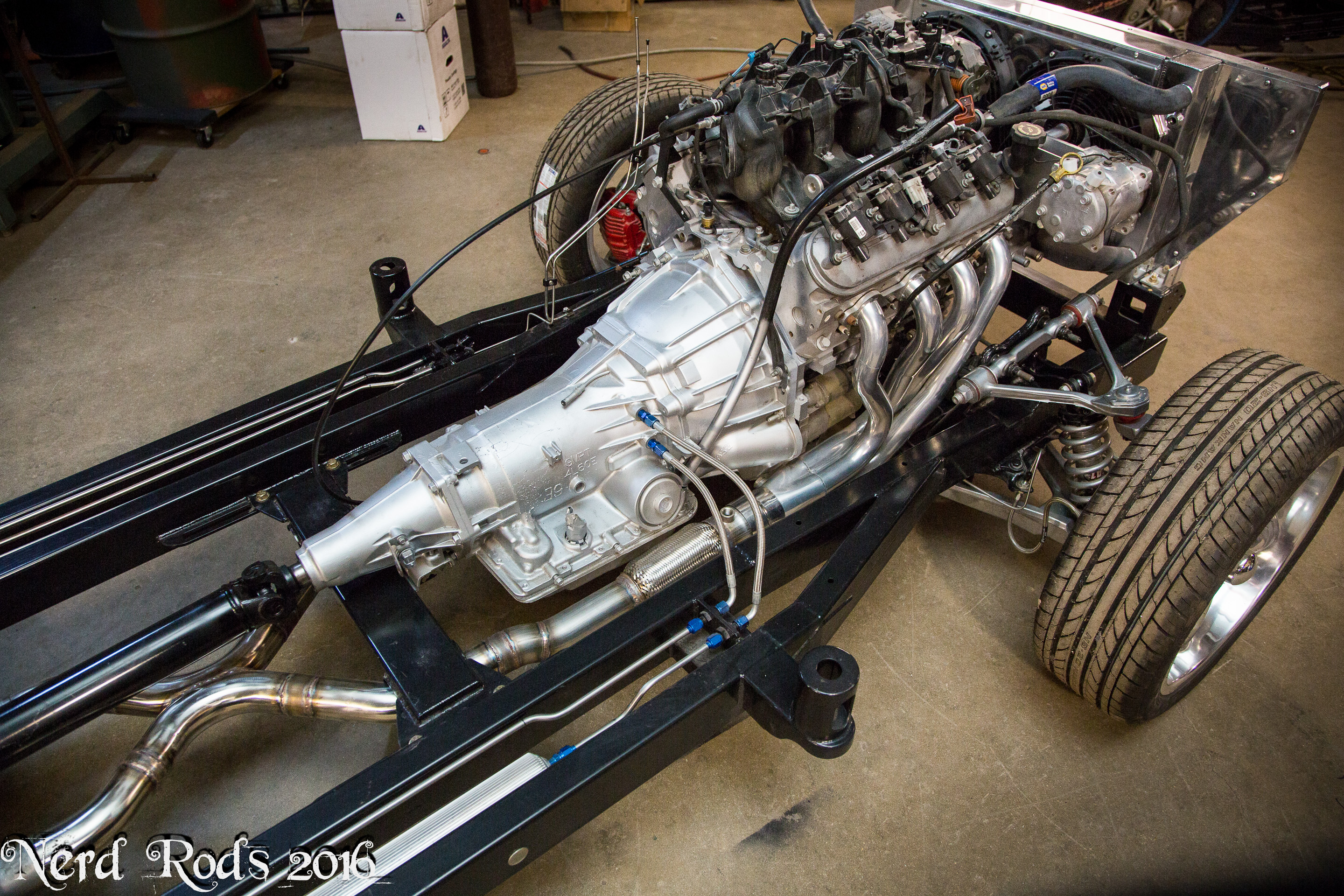
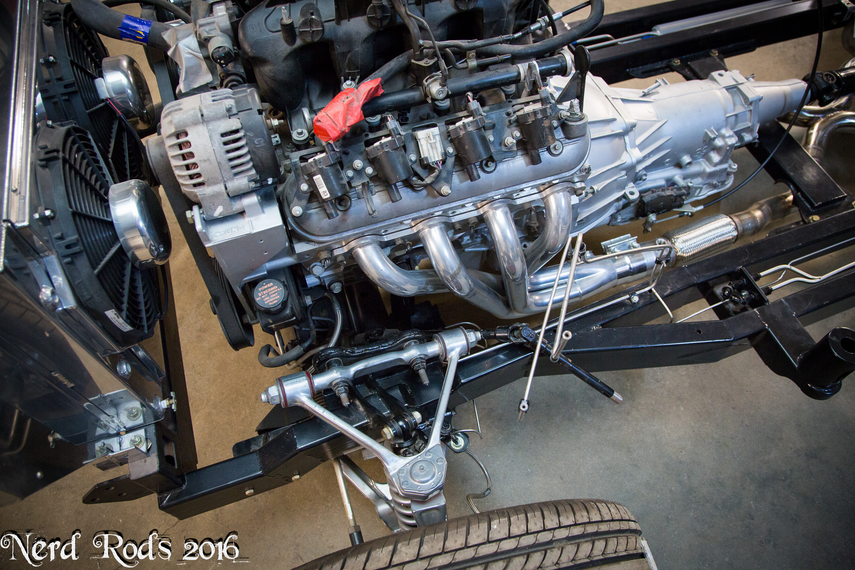
You can see here some of the clearance considerations to go with the firewall and radiator clearance. Also remember, this is the deep 5.3L Truck oil pan so with the correct pan the engine could be lower giving more room to the firewall and requiring less modification. Also the truck pulleys stick the furthest away from the block so a Camaro or Corvette pulley system would again let you get the engine further forward and again give more room to the firewall.


Hope to have that video soon!
-Russell @ Nerd Rods
The easy flip through gallery is here ( http://gallery.nerdrods.com/Customer...ake%20Webb/03/ )

You can see here some of the clearance considerations to go with the firewall and radiator clearance. Also remember, this is the deep 5.3L Truck oil pan so with the correct pan the engine could be lower giving more room to the firewall and requiring less modification. Also the truck pulleys stick the furthest away from the block so a Camaro or Corvette pulley system would again let you get the engine further forward and again give more room to the firewall.


Hope to have that video soon!
-Russell @ Nerd Rods
08-26-2015 | 03:06 AM
#116
Thread Starter
Launching!
Joined: Jan 2007
Posts: 294
Likes: 3
From: Luling TX In the Hot Rod Shop
Figured this would help answer some questions about the fit and clearing we had to do. This will basically apply to all task force trucks with C4 suspension so enjoy.
09-28-2015 | 04:18 PM
#117
Thread Starter
Launching!
Joined: Jan 2007
Posts: 294
Likes: 3
From: Luling TX In the Hot Rod Shop
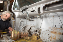
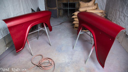
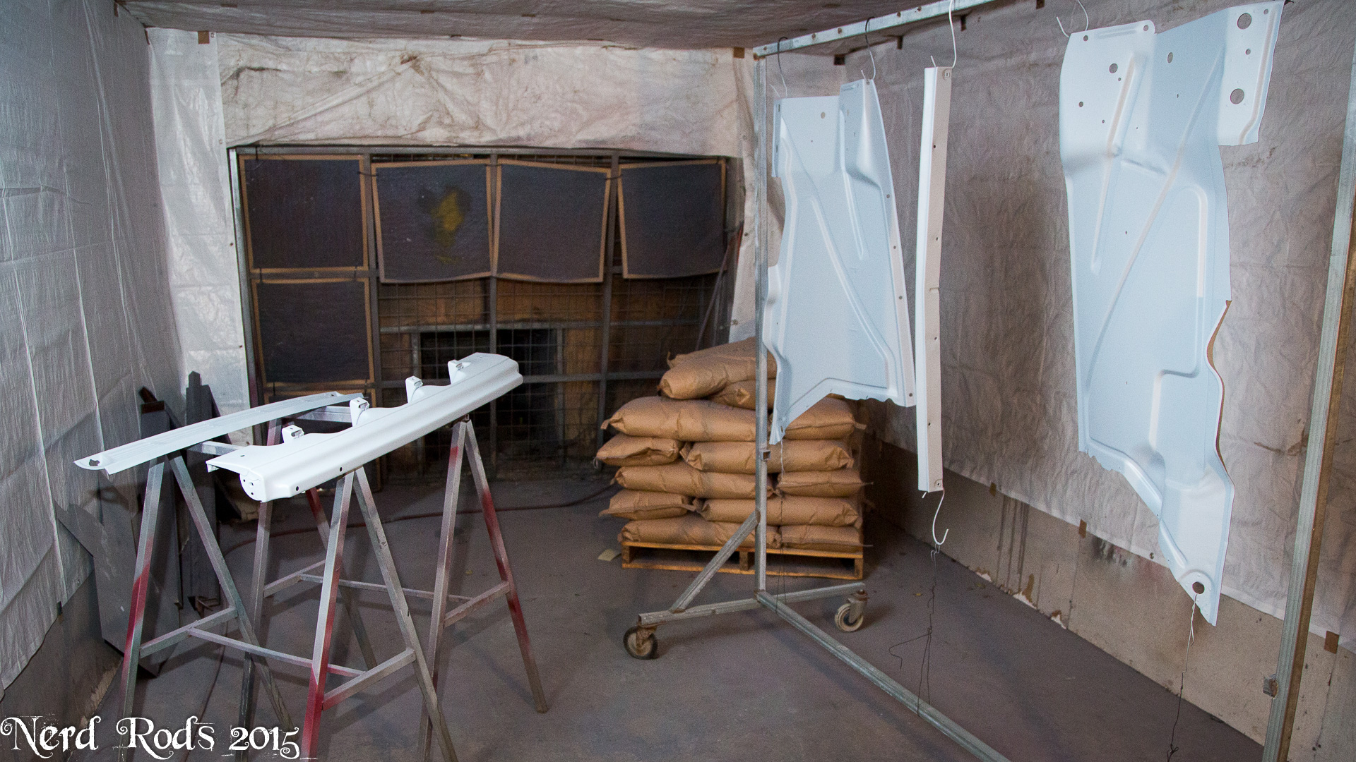
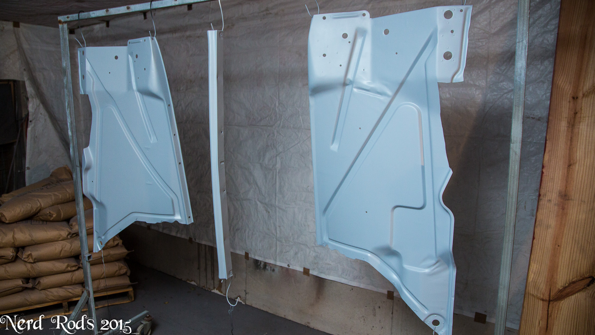
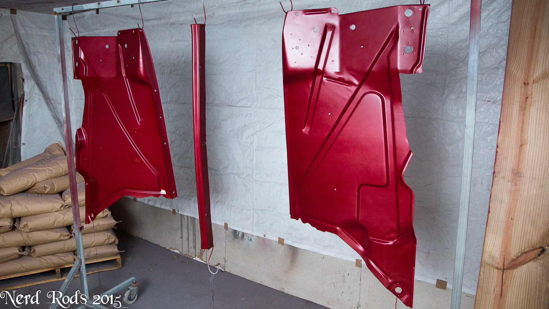
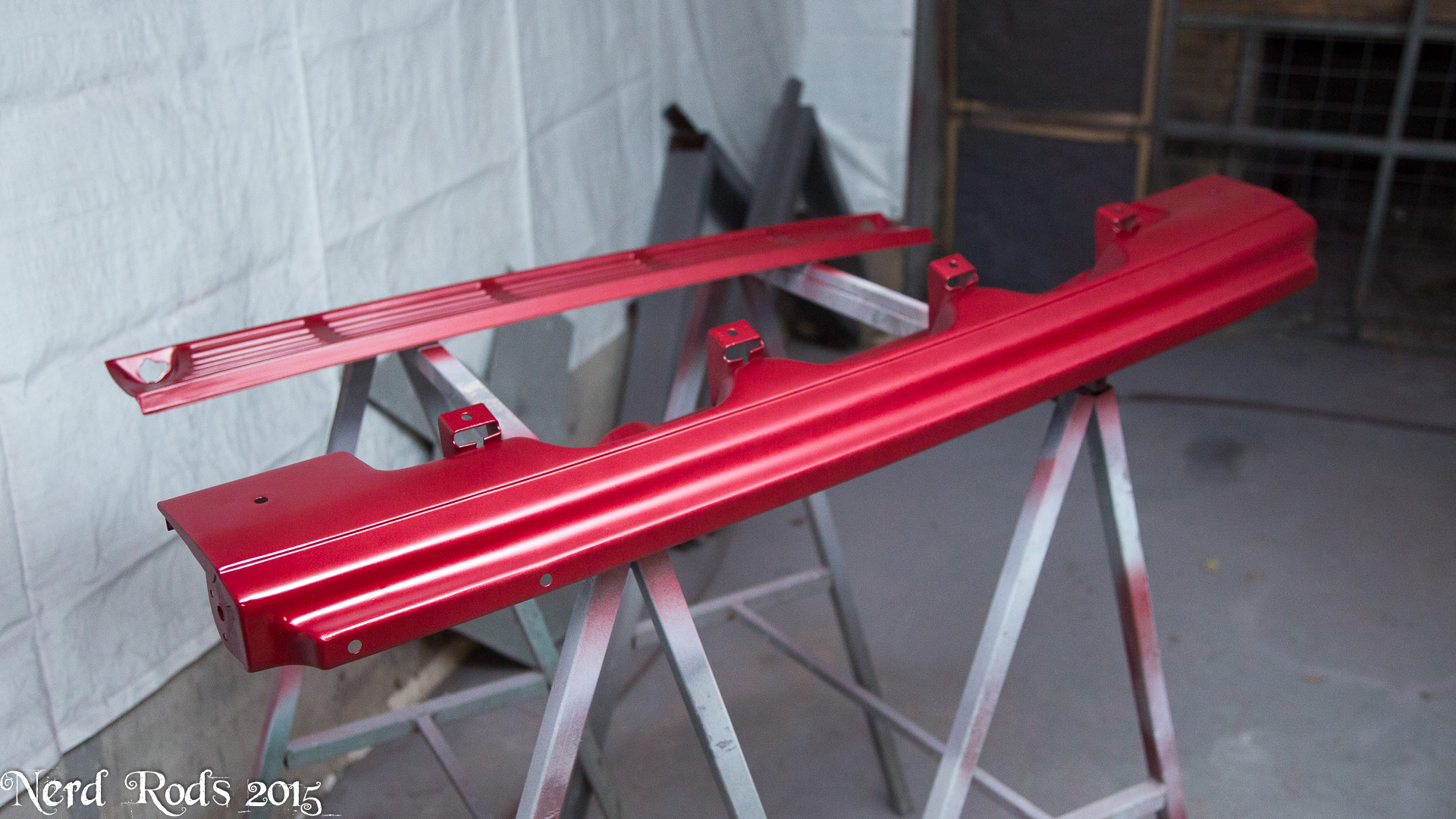
Finally getting back on the original truck we started on. The customer wanted it painted and so I've been trying to sort that bag of worms for the last several months. First I tried to out source it, talked to several painters, most never showed up after saying they would, some wouldn't do what the customer wanted done and a few gave me a bad vibe. I've learned with painful reputation that I need to listen to my gut on things like that so those guys were a no go. Finally I decided to just spray it here. Waited on a paint booth to rent that ended up not working out. Finally a few days ago I had my minion clean the back up, threw the hood on the stands and painted the damn thing. Did the fenders later that day and so fourth. I would be painting the cab right now but my glasses got FUBAR'd yesterday and my prescription changed so now I'm adjusting to new glasses before I dare spray the cab.


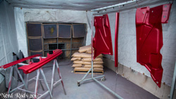


More photos soon. I hope to paint the cab when I wake up. We are fixing a few things I don't like about the exhaust at the moment and bolting down the last of the brake lines. Then its body install time for the last time!


More photos soon. I hope to paint the cab when I wake up. We are fixing a few things I don't like about the exhaust at the moment and bolting down the last of the brake lines. Then its body install time for the last time!
01-28-2016 | 08:50 AM
#118
Thread Starter
Launching!
Joined: Jan 2007
Posts: 294
Likes: 3
From: Luling TX In the Hot Rod Shop
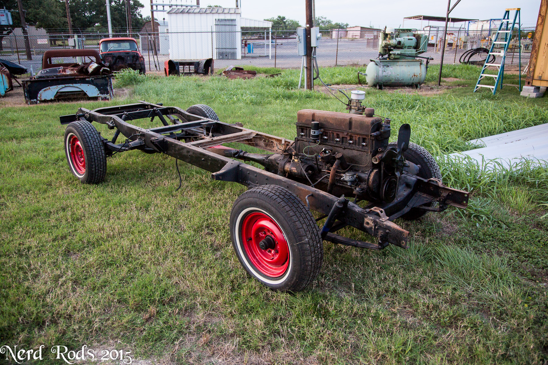
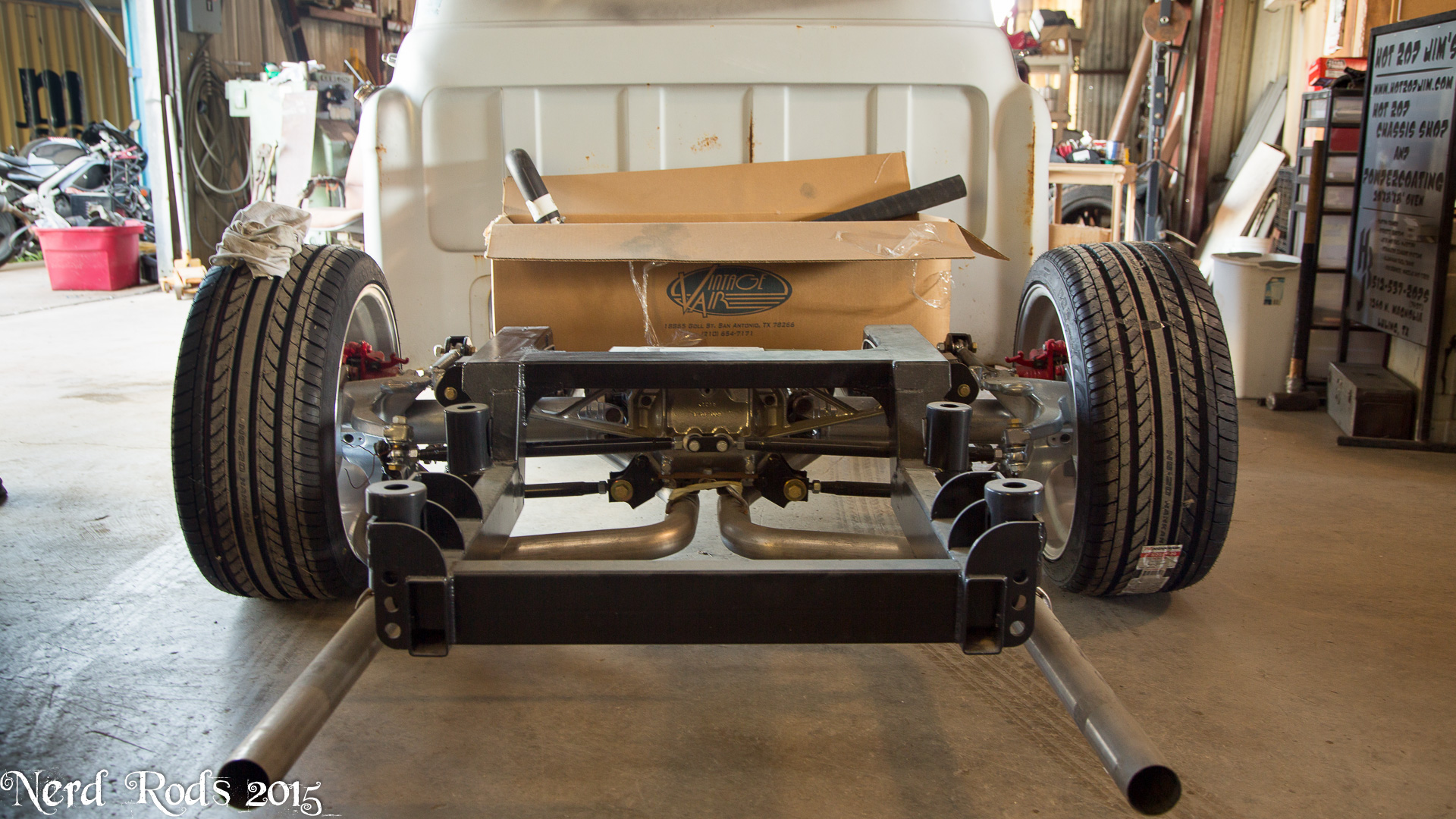
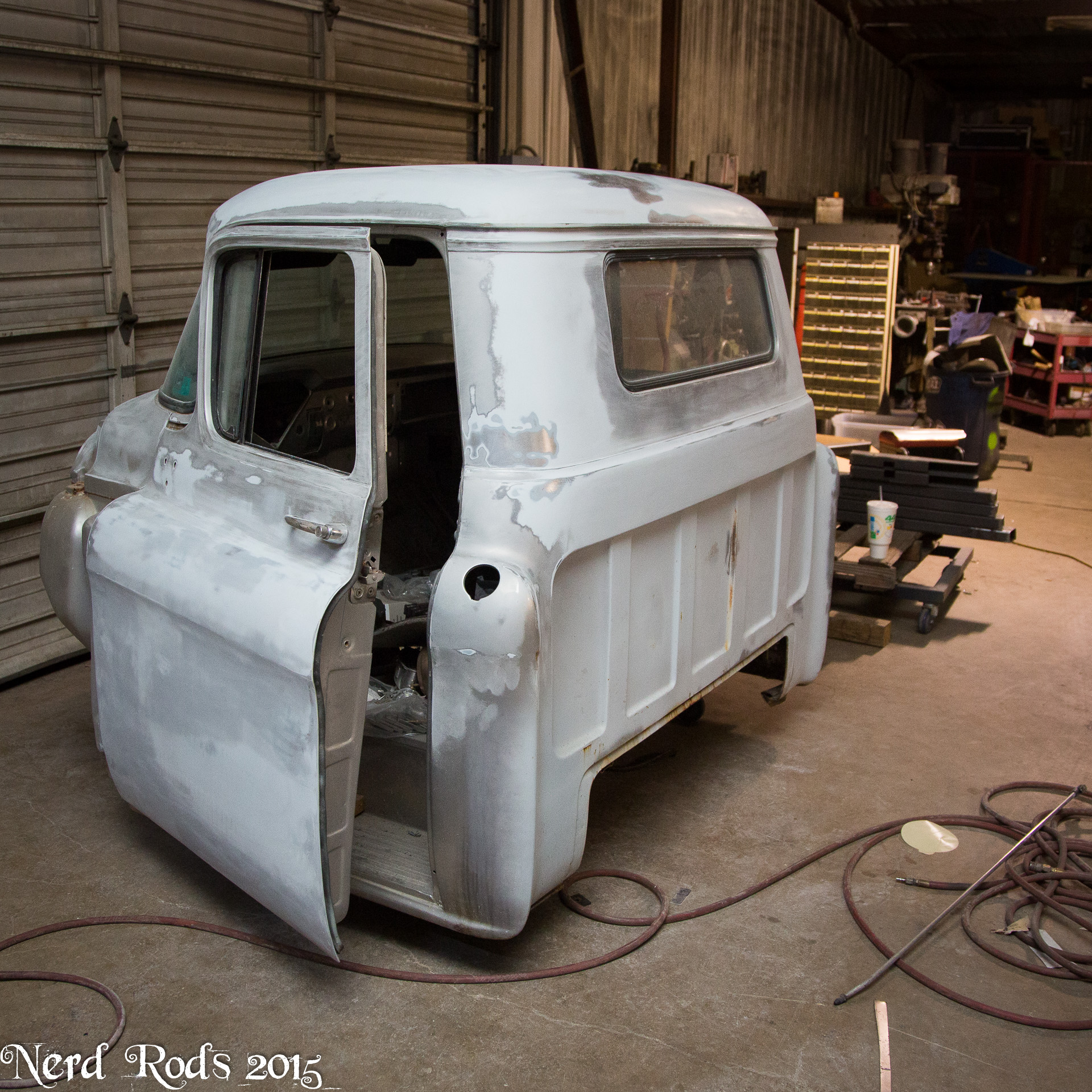
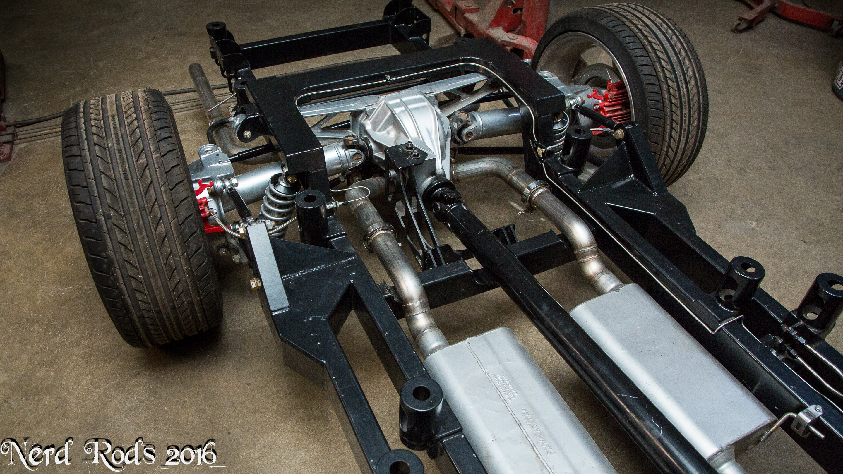
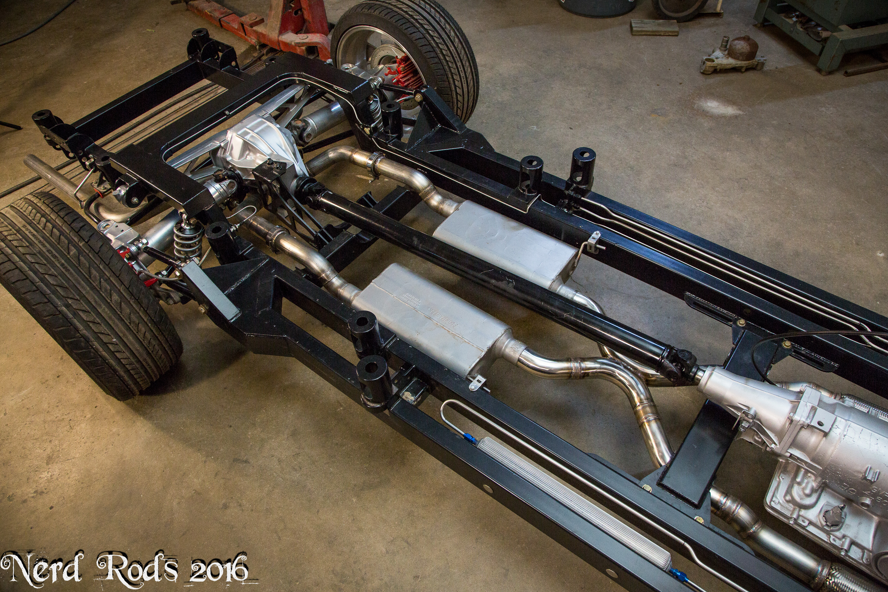
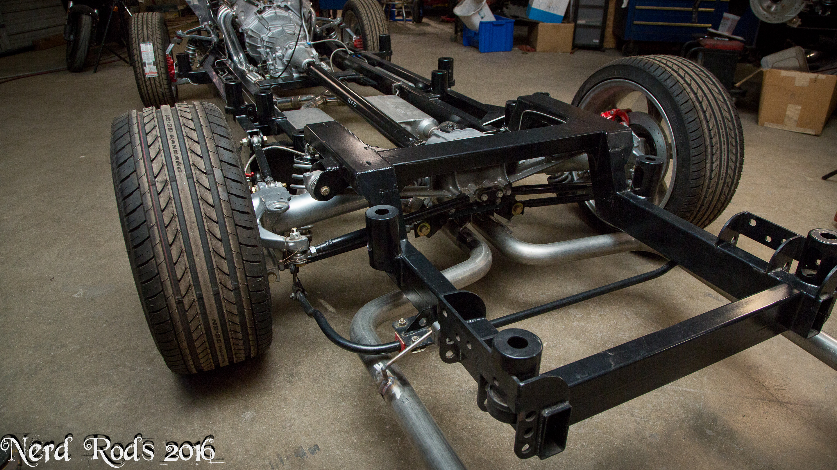
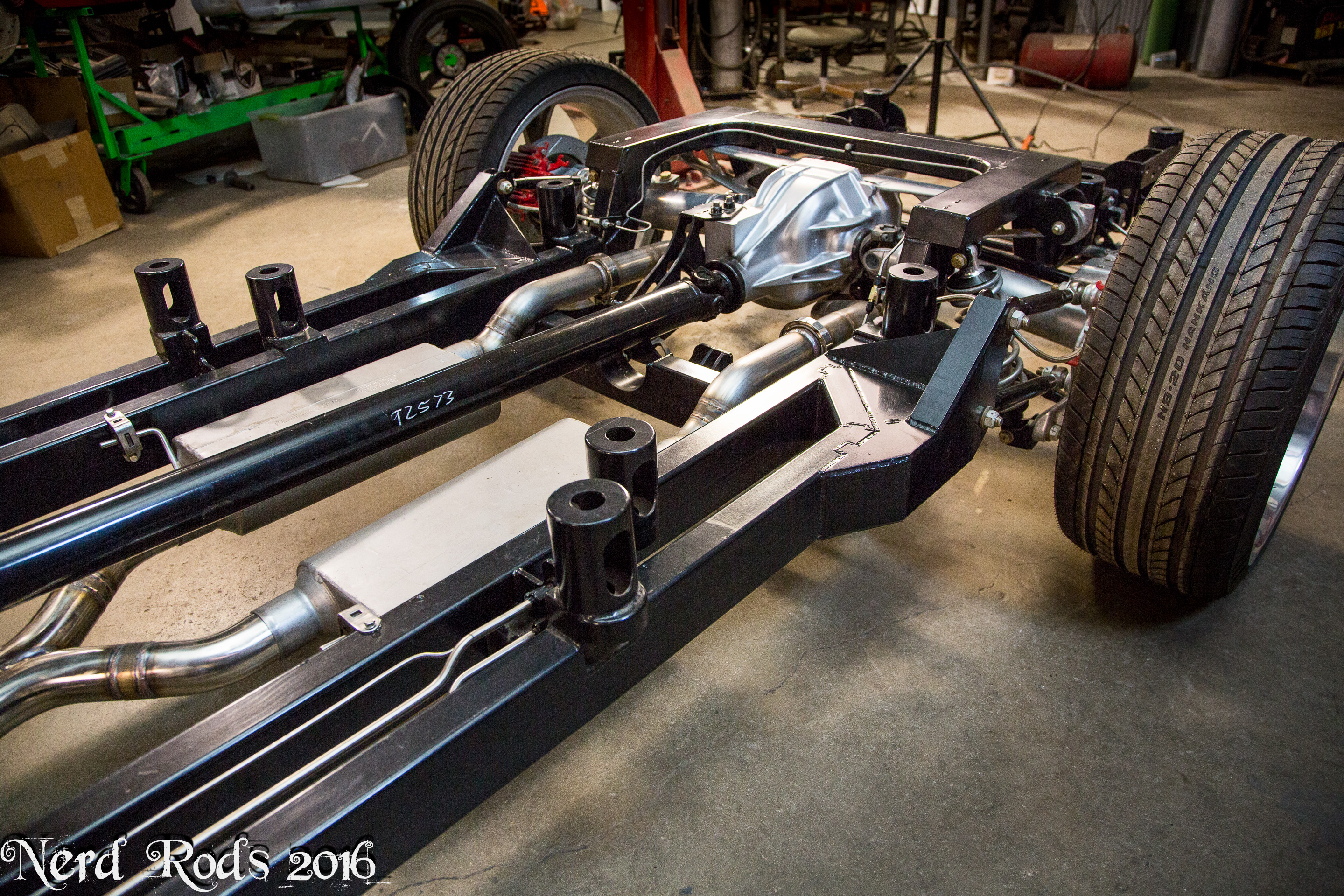
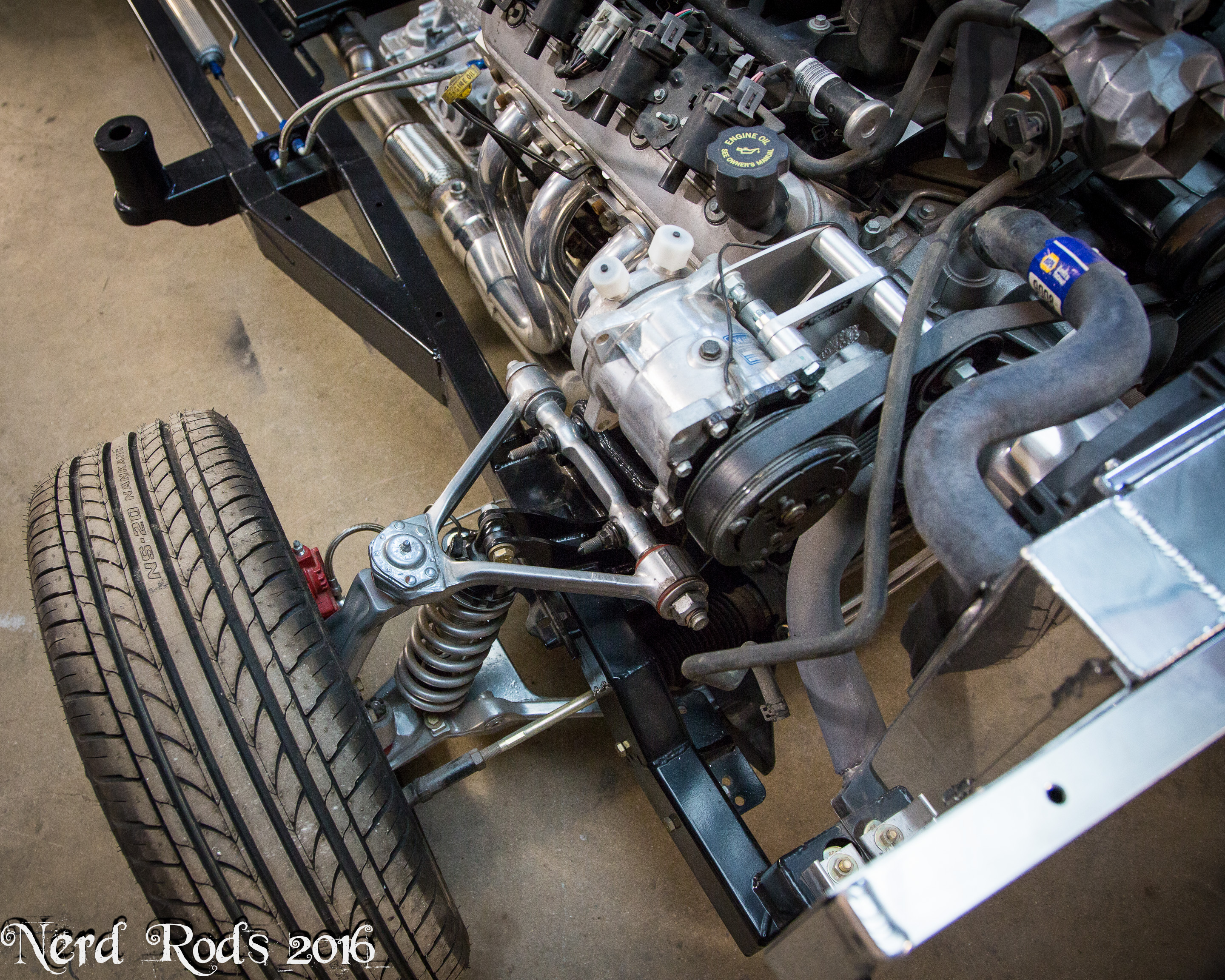
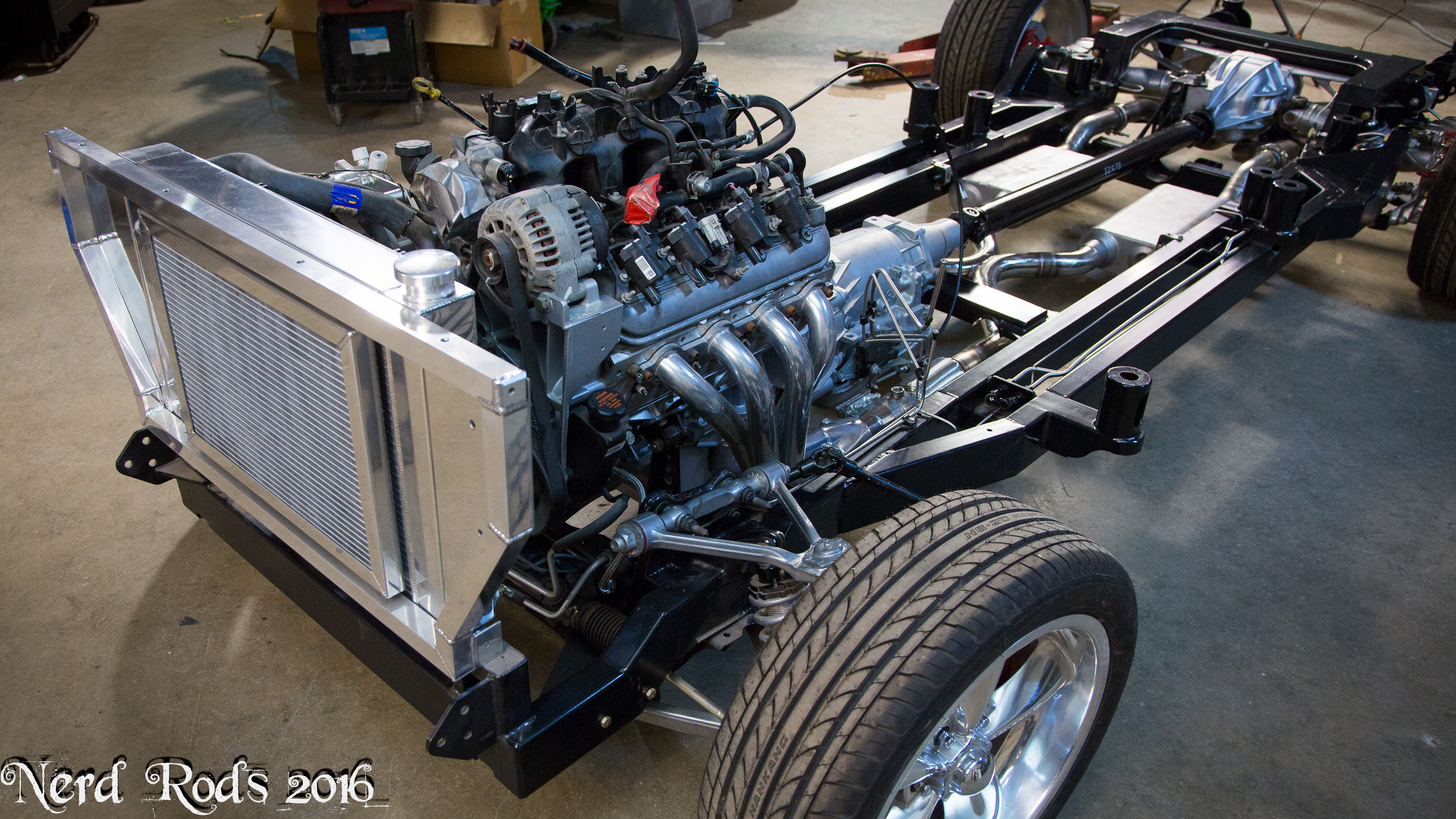
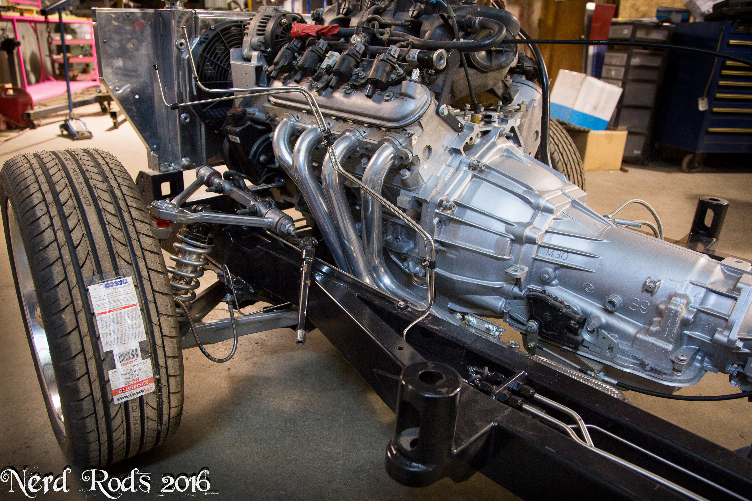
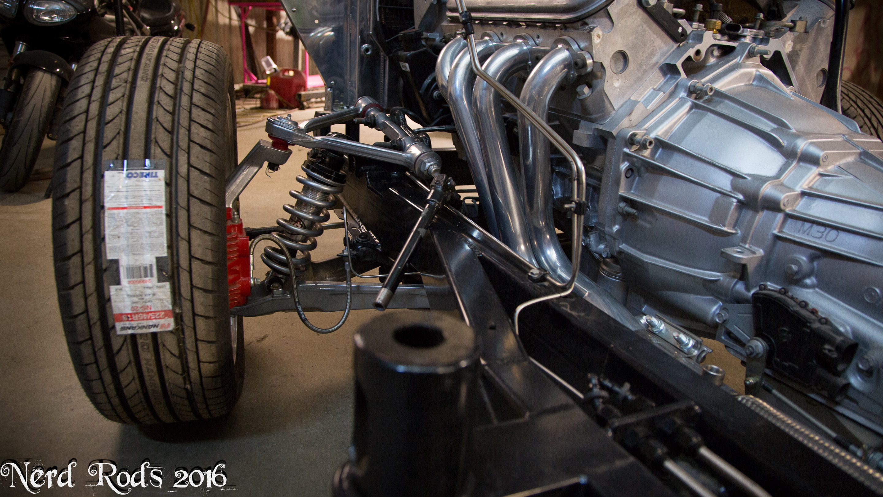
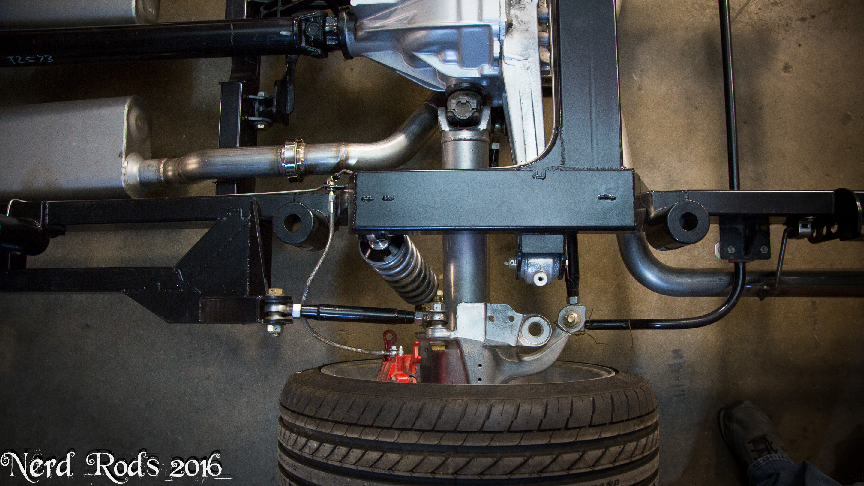
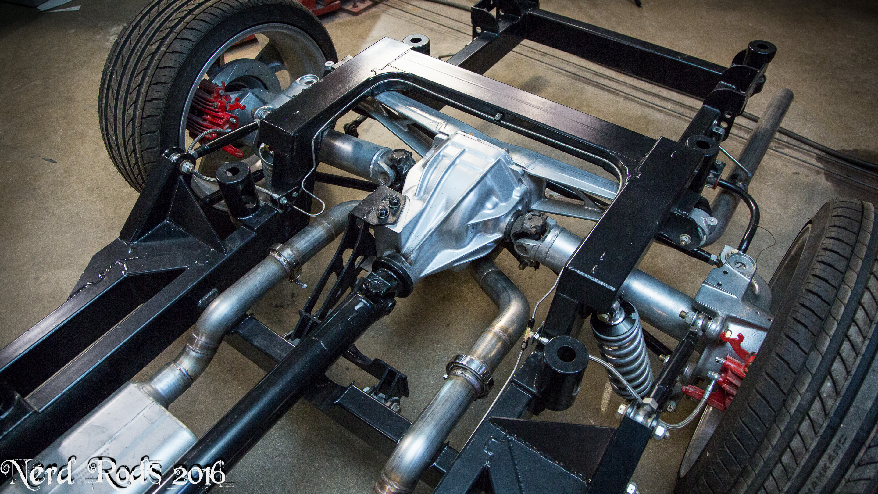
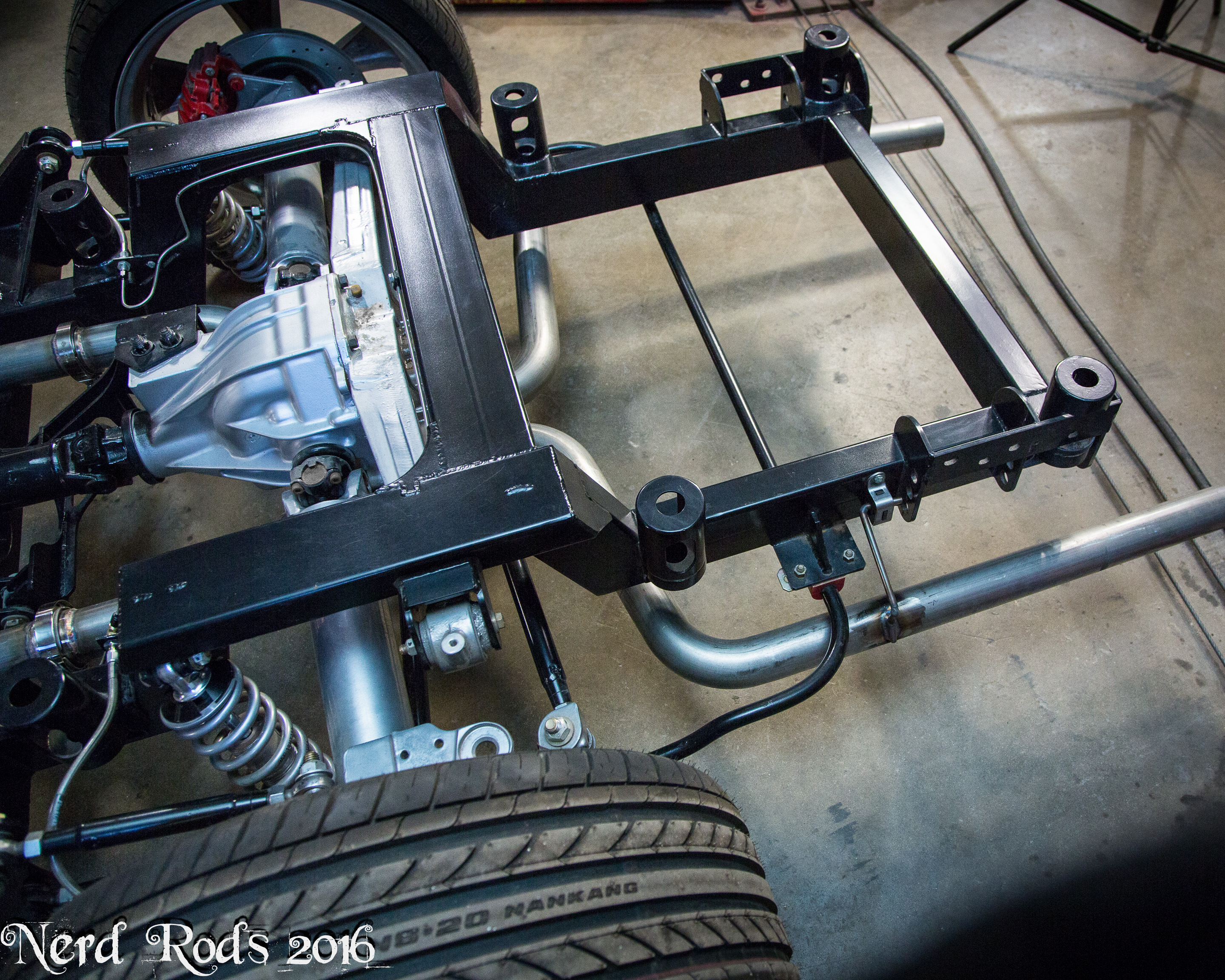
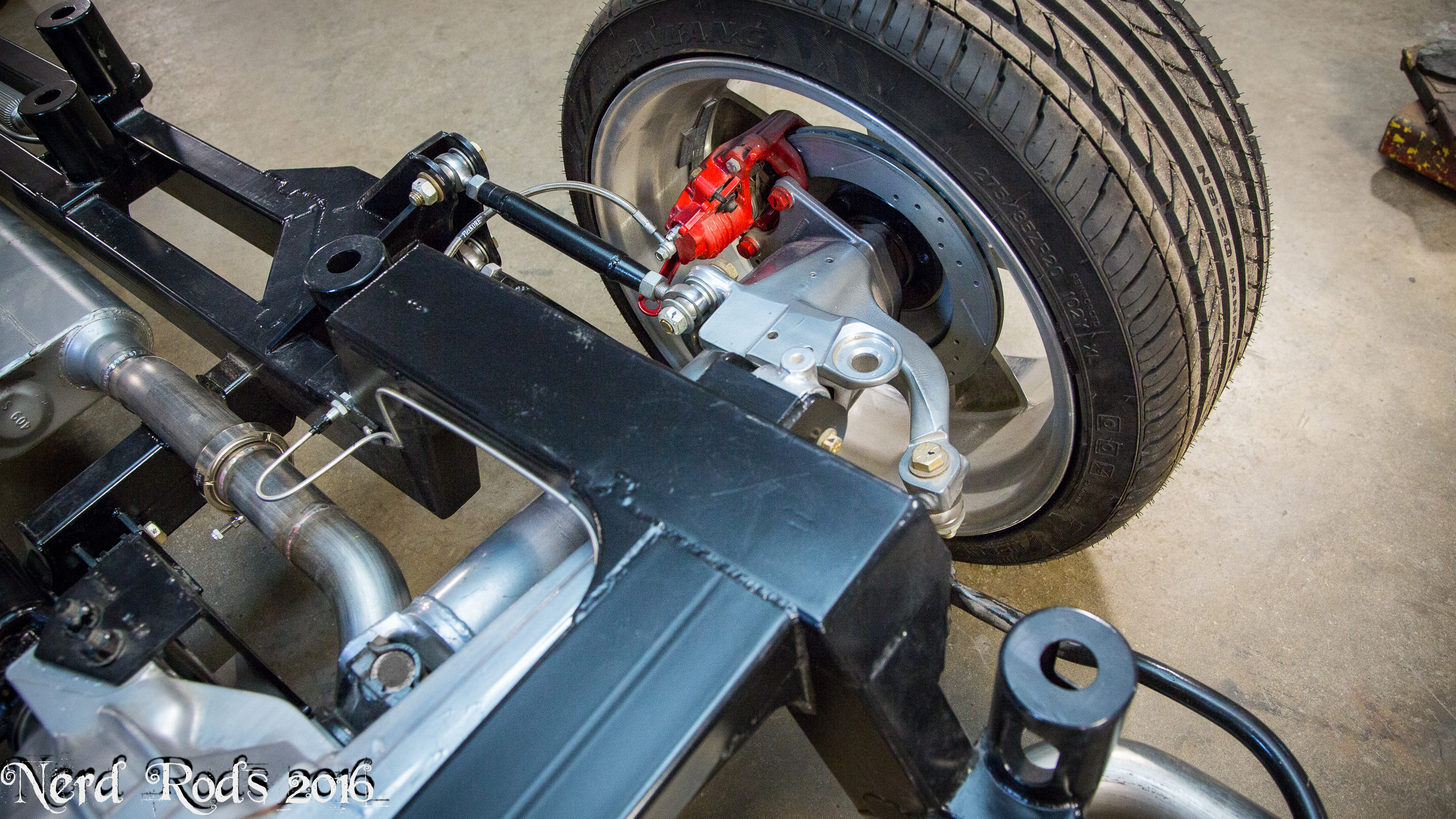
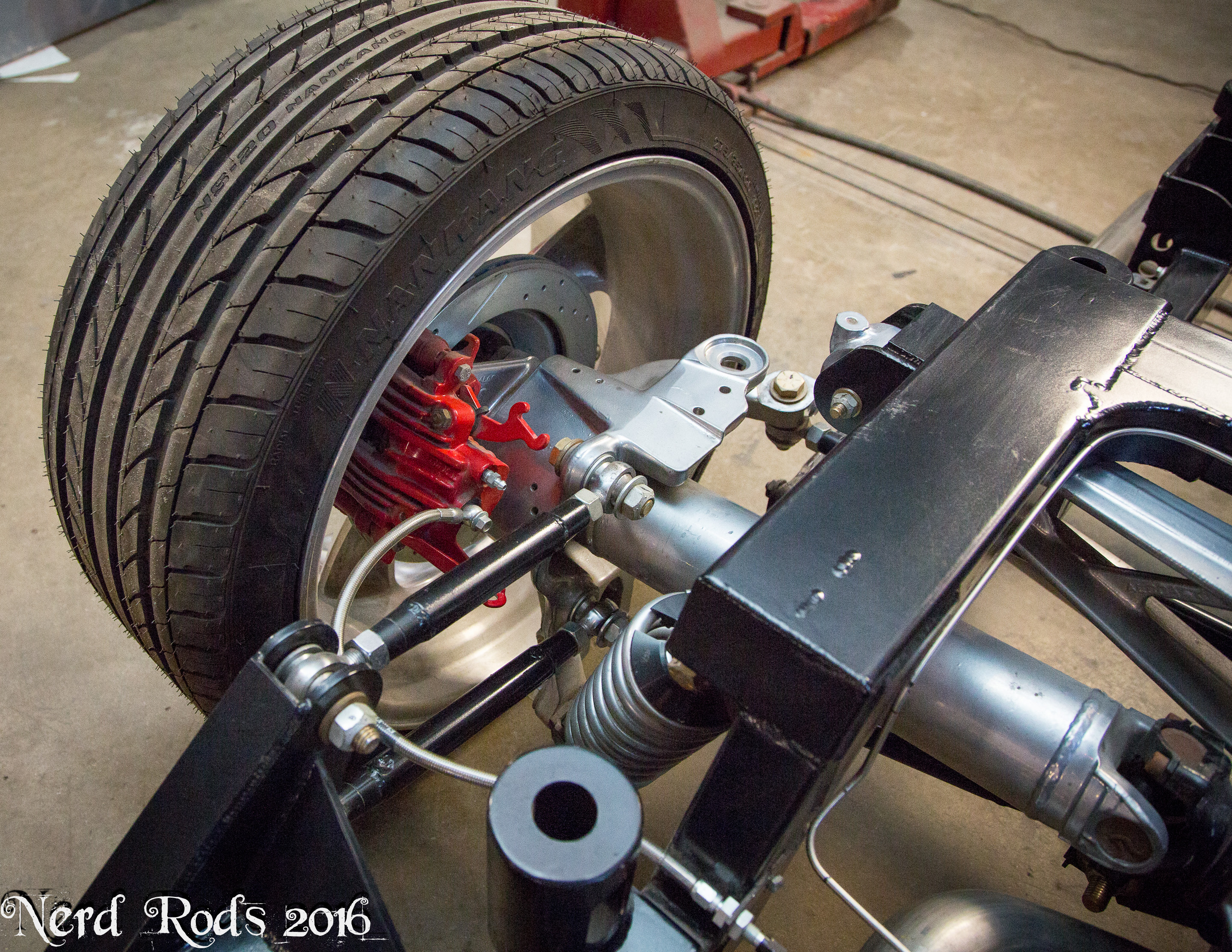
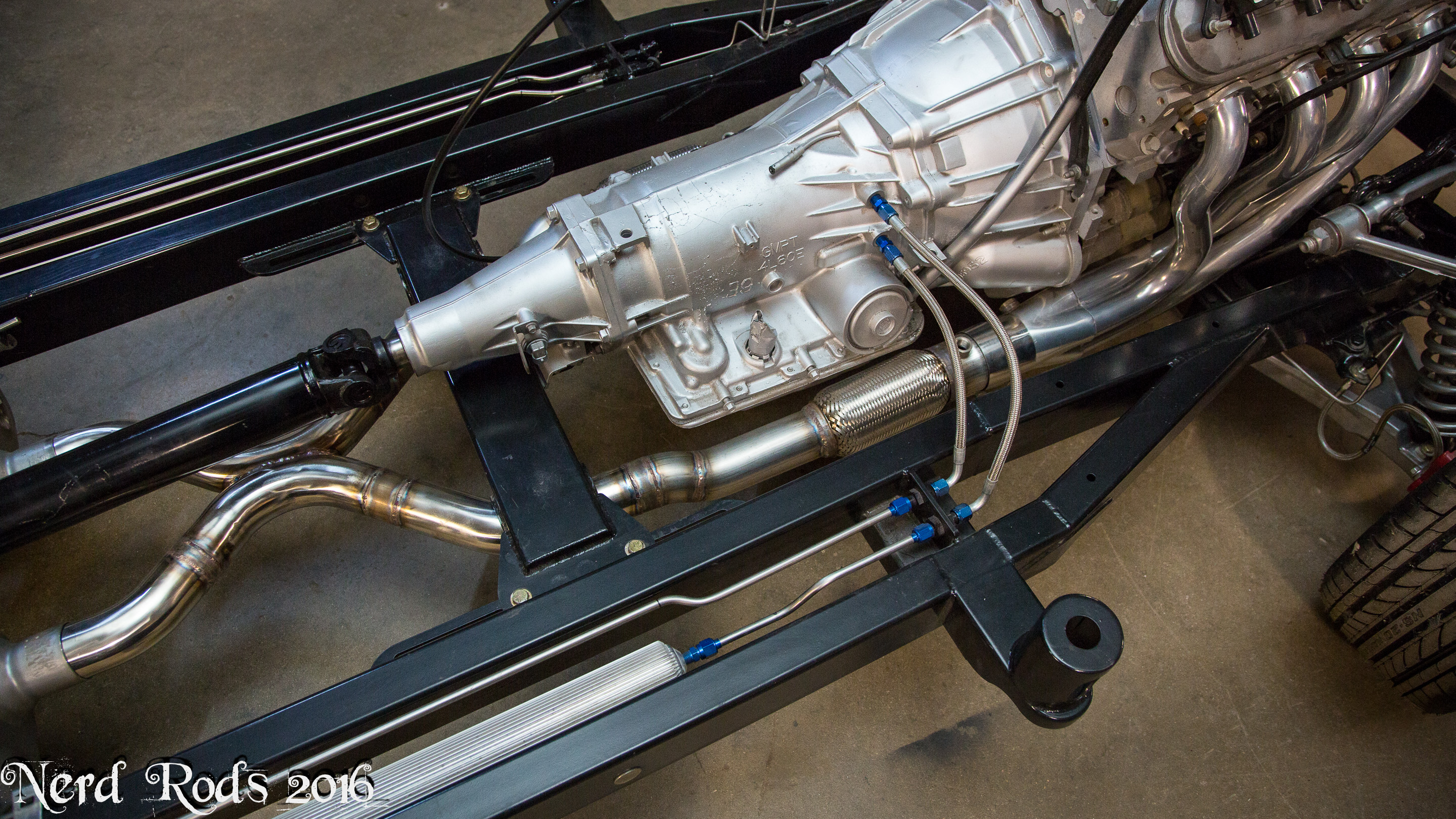
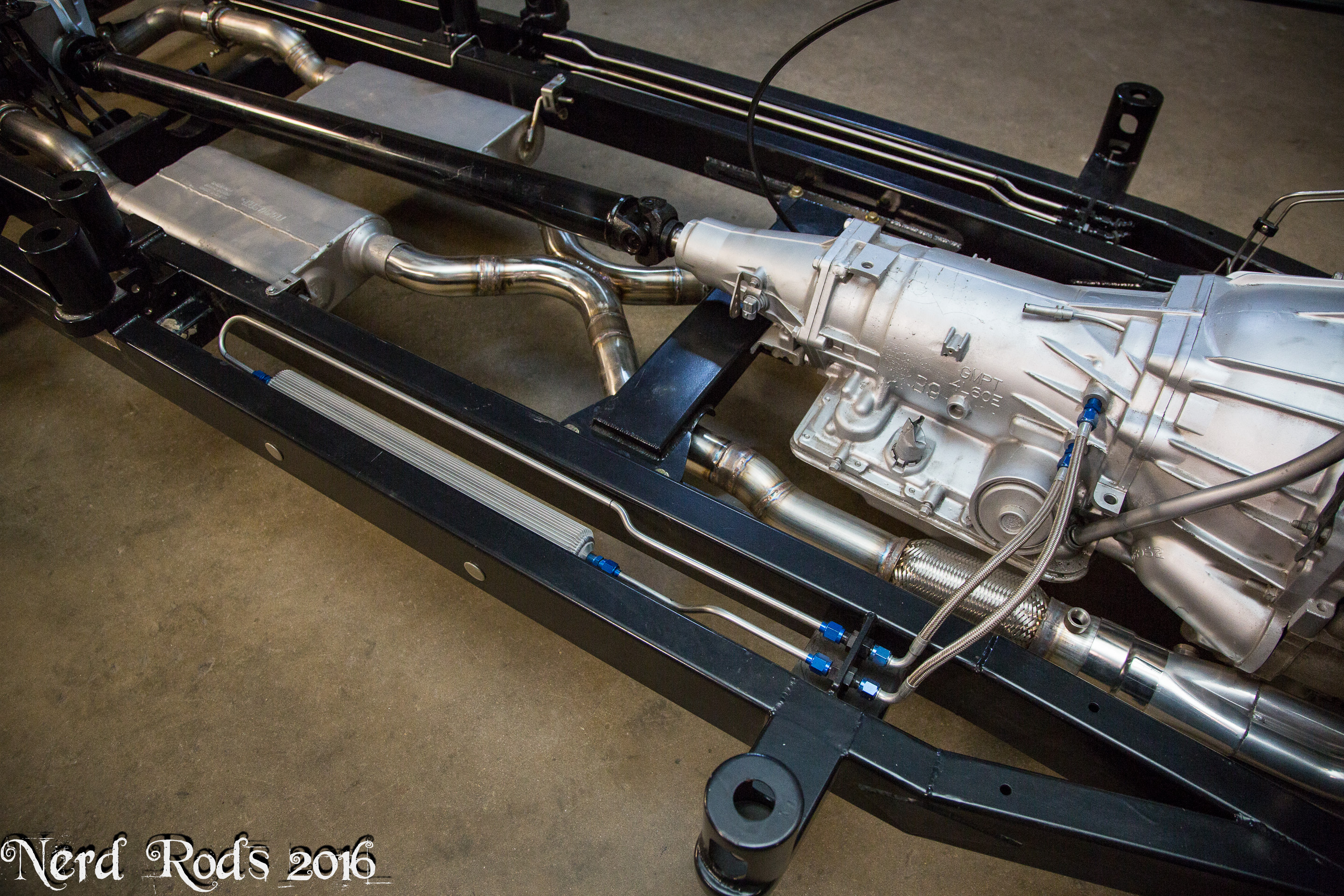
I had to do some modifications to the exhaust on this one that took longer than expected. So with that the chassis is completed and I got a last set of photos before the body goes on one last time.
Easy viewing gallery here.
http://gallery.nerdrods.com/Product/CP5559C4/S3.01/


Later
-Russell @ Nerd Rods
Easy viewing gallery here.
http://gallery.nerdrods.com/Product/CP5559C4/S3.01/
Later
-Russell @ Nerd Rods
Last edited by rat_rod_russell; 01-28-2016 at 08:58 AM.
01-28-2016 | 12:28 PM
#119
TECH Resident
Joined: Feb 2014
Posts: 954
Likes: 9
From: Encinitas CA
Beautiful work. That chassis really looks amazing.
interesting trans cooler you installed. Is that finned tube sufficient? I don't doubt your decision, just curious if you've installed those on others?
Doug
interesting trans cooler you installed. Is that finned tube sufficient? I don't doubt your decision, just curious if you've installed those on others?
Doug
01-29-2016 | 11:56 PM
#120
Thread Starter
Launching!
Joined: Jan 2007
Posts: 294
Likes: 3
From: Luling TX In the Hot Rod Shop
-Russell