When you click on links to various merchants on this site and make a purchase, this can result in this site earning a commission. Affiliate programs and affiliations include, but are not limited to, the eBay Partner Network.
Interesting. But your findings lead me back to an offshoot the question I asked earlier.
Do you know what motor mounts were used in yours? Do you know if they jury rigged them to raise the engine high enough to clear the crossmember?
So, it sounds like you are tackling other items to arrive at the correct angle (which I presume...whatever it takes to get the right angle). But the overall question for me is then the same...if the install did not have something done to clear the cross member, and the mounts weren't rigged for the clearance, then that means the mounts used in yours should probably be avoided whether the xmember is notched or not.
I probably confused the heck out of everyone with above
I can't see any brand name on the adapter plates ( I believe they were bought from ebay), but most are pretty much the same, just a flat plate with holes in the proper position to use a common sbc motor mount, they didn't modify anything to make them fit
the only thing i had to do to get the correct driveline angle was raise the back of the transmission about 1 inch, which is what i was trying to explain in my last post, anyway, I would say just put the F body pan on and drop the motor in to see where you're at
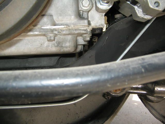
on my 59 with ls1 (02 camaro pan) a small notch was needed on the passenger side. I only needed to notch the crossmember enough to make the flat area a little wider, so the PS corner of the pan doesn't hit it.
I'm starting to think that there may be some variations in the frames of these old cars, someone had mentioned on another forum that the x frames were known to bow at the crossmember over time. We have half a dozen of these cars at the shop, I may have to compare measurements on a few for curiosity sake, it might explain why some people have clearance issues and some don't.
I'm starting to think that there may be some variations in the frames of these old cars, someone had mentioned on another forum that the x frames were known to bow at the crossmember over time. We have half a dozen of these cars at the shop, I may have to compare measurements on a few for curiosity sake, it might explain why some people have clearance issues and some don't.
Or could it be that some people don't know (or care) about improper driveline angles and the potential problems that can cause?
Or could it be that some people don't know (or care) about improper driveline angles and the potential problems that can cause?
Russ
I'm sure that in general, it would be "don't know".
But, I have to say, if a person purchases motor mounts from a reputable and knowledgeable source, such as S&P, and use their suggested pan (98-02), and they don't hit the frame/crossmember, haven't been told by them that notching is necessary, there would be every expectation that the drive angle would be correct. (Notice I said expectation...not necessarity fact).
It is interesting the various experiences being posted here. Maybe flexing of the frame is part of the reason.
What I've learned with this is that I need to be prepared to notch the crossmember; and that I need to get the tool necessary to measure the angle of the engine, and make sure it is where it should be.
on my 59 with ls1 (02 camaro pan) a small notch was needed on the passenger side. I only needed to notch the crossmember enough to make the flat area a little wider, so the PS corner of the pan doesn't hit it.
Russ
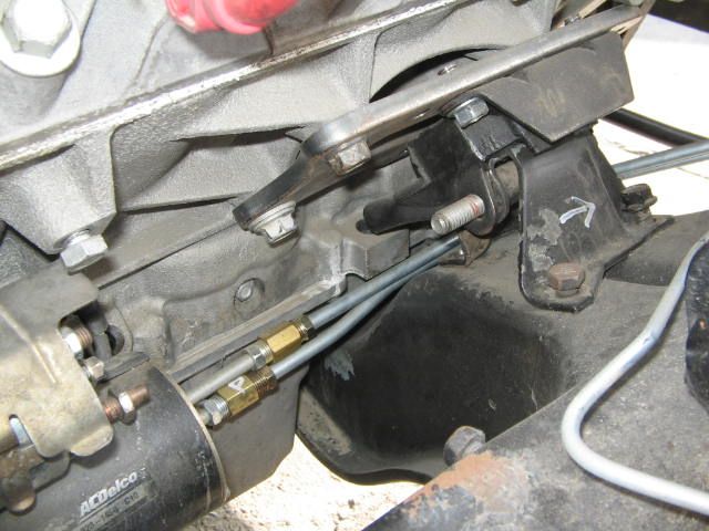
The stands in this picture look taller like the original inline 6 cylinder mounts. The original v8 stands are shorter and set closer to the crossmember.
The stands in this picture look taller like the original inline 6 cylinder mounts. The original v8 stands are shorter and set closer to the crossmember.
That's interesting. That would make a big difference in whether, or now much, to notch.
The stands in this picture look taller like the original inline 6 cylinder mounts. The original v8 stands are shorter and set closer to the crossmember.
I need to figure out if my stands are V8 or 6 Cyl stands. That would certainly make a difference. If 6 cyl, and higher, may clear but be wrong angle; if V8 and lower, may work for angle, but hitI cross member.
I'm betting that is why all the difference experiences, and also then, those that clear are not checking the angle.
I called and talked to Mark at Street and Performance, and he said he is doing a 61 right now, and that it clears with his mounts and tranny mount, but to get the right angle, he too raised the transmission at the back.
I have decided that I am NOT going to go with the Dirty Dingo mounts (allows moving the engine forwrd, or not), because they involve yet another plage which would take the engine even higher.
I need to figure out whether I have 6 or 8 cyl motor stands. I plan to check and make sure the engine angle is correct. If I can do that without cutting the crossmember, raising the tranny, without the tranny hitting the tunnel, I"m going that way. Otherwise, I'll likely be cutting the cross member.
Well, due to reasons I won't go into, I had a time issue and had to get the engine dropped in.
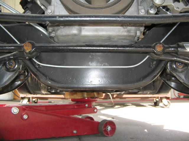
I have determined that the mount stands in mine are for a 6 cyl car, and the pan does NOT hit the cross member.
BUT...the engine looks to be at quite an angle. Haven't measured yet, but will be doing that. I suspect that I do have a little room to raise the tranny, but I'm doubting it will be enough.
this is my 2 cents. I’ve had a lot of x frame(1959-1964) vehicles over the years and ran into this problem a few times. Now I’m building a 59 El Camino with a LS1 . One of the main reason why these X-frame vehicle need the correct angle is the 2 piece drive shaft. If the drive shaft doesn’t have the correct angle it will vibrate at a certain speed and could destroy the drive shift. So if you have a motor at 4 plus degrees and the rear end differential at 2.5 to 3.0 degree and the center of the drive shift to high or to low at the center Carrier Bearing it will start to vibrate at about 40 plus mph. It ‘s all in the 1961 Chevy manual on how to get the correct angles. All other vehicle have a one piece drive shaft with no center Carrier Bearing and you can change the angle on the differential to correct this.
What I did was to move the LS1 forward 1 inch using mounts that I modified from seller “phoenix_design” on ebay. I then knoched the cross member. I also cut the lower frame mounts by 3/4 of an inch to get the correct angle. Where The Transmission cross member mounts to, it has two holes, an upper and lower, I used the lower. In my opinion the mounts everybody sells are way to thick. God willing and the river don’t rise I’ll start a thread in January.
Wow. You had to do multiple things for the clearance.
Given that I've determined my stands are 6 cyl. my next step will be same as Aaronbang: raise trans by an inch. The big question is how the angle comes out. Of course, even if the angle that the engine sets at is correct, the next question will be if the angle to the driveshaft ends up being off.
Assuming failure, my next step will be to try mounts that bring the engine forward 1".
After that, I'll likely be pulling the engine to notch the crossmember.
If I hadn't used S&P transmission mount (it requires cutting off the tabs that the original mount bolted to), I'd use the BRP kit, which their marketing info say lands the engine and tranny at the right angle. But, with those tabs gone, I can't use their transmission mount.
Aaronbang...if you see this thread now...I just re-read you earlier post, and you had indicated you still had a bit of a problem after flipping the transmission mount to raise it up. You were considering trying shaving off the carrier bearing.
ewingr, read your postings on Chevy Talk, interesting. I’m also a member there. Anyhow on X frame vehicles only. Your only suppose to move the transmission up or down, what the transmission frame tab allow. The drive shaft is only 2” in diameter not 3” or more like all others Chevys, Plus when you move the transmission up your only moving the front section of the drive shaft. Adjust the angle of the motor at the front not the transmission.
I used the steel mount plates sold by phoenix_design “eBay item number:361372381265” I like these because you can cut them and weld them to your build. Plus there are only 15 buck or so. If there isn’t any up for sale e-mail him.(my 2 cents)
I just read through the Spicer Driveline Installation manual linked early in the thread. Good info.
I have my work cut out for me. I really hope I don't have to pull the engine and notch the cross member, but I'm beginning to think it going to have to happen.
Well, it's been an interesting exercise measuring. Anyone with knowledge of this process that spots flaws with my process or placement for measurement, please chime in.
Initial important note: I did not have weight on the tires. Given that these wheels and tires are not finals, and no driveshaft in either I proceeded as follows for some initial thoughts:
First thing I wanted to do was get the frame level. In the end I understand that the ride height and whether the car is level, etc., makes a difference measuring.
Not having the final wheels and tires I decided to to the measurements by having the frame level at center. I'm sure there can be tolerances that make a difference, in particular with where I measure.
I'm a bit concerned about the Harbor Freight tool I am using to measure. I got the one linked early in this thread. I find that the needle may take several seconds to settle from wobbling back and forth, but at other times it is almost like it is sticky on the axis and stops pretty quick. It appears to depend on where I mount the tool as to whether this happens or not.
With Transmission mounted at lowest position
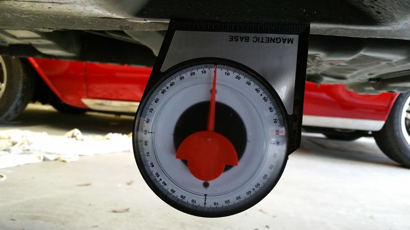
So, here is a shot of my measurement for setting level at the frame:
That measurement is very close to 0.
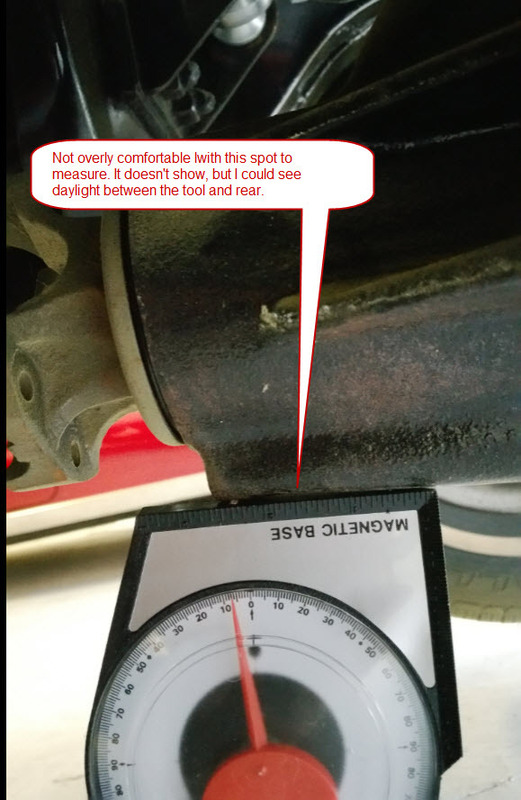
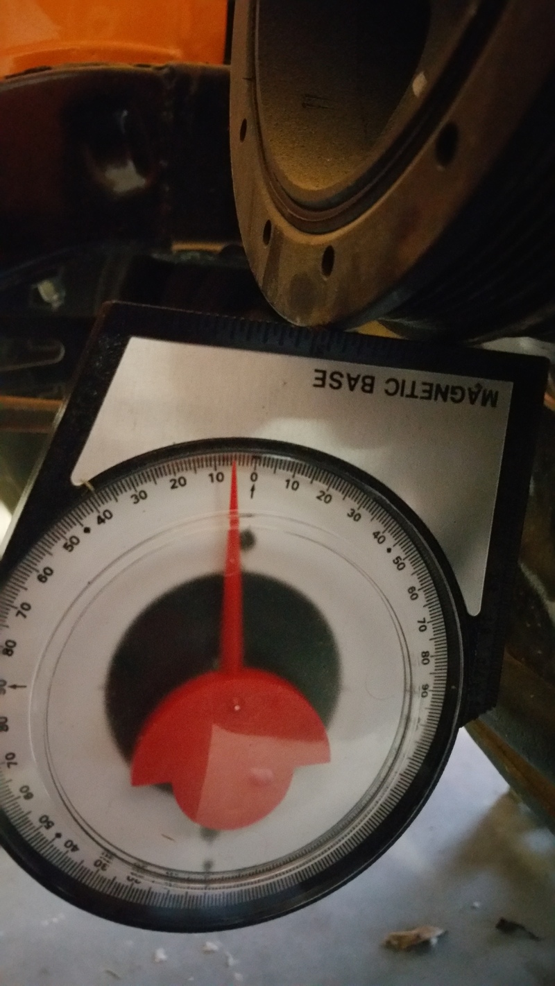
Next is the measurement at the rear end. I found that mounting the tool on the very bottom I could see daylight at one point under the tool, making it appear that at the front of the rear end where the tool mounted that it dropped a little. This is the picture of that:
That measurement is right at 7 degrees down.
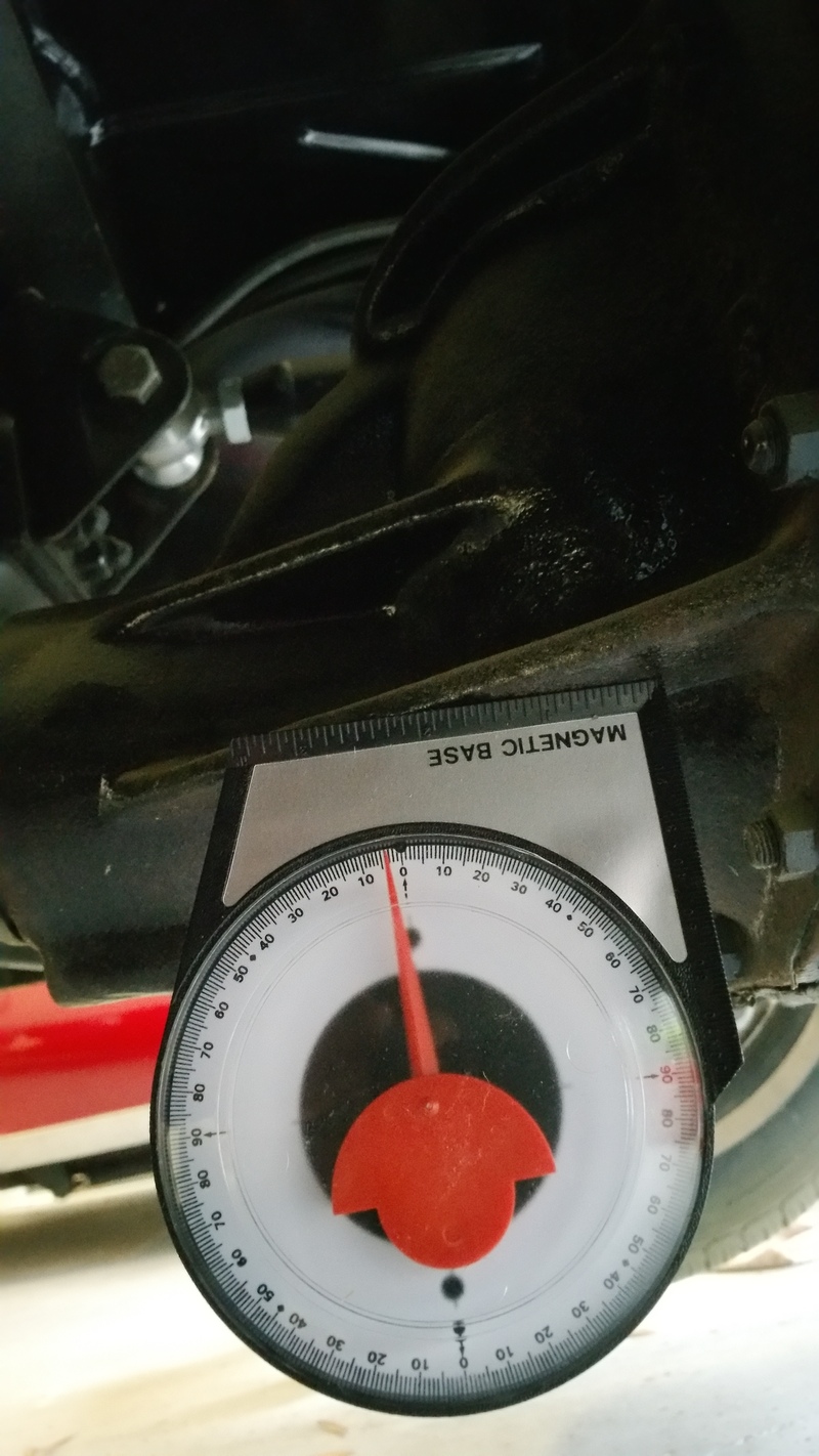
The next picture is measuring on the angle brace which the tool fit nice too, and it appears to me that it should be parallel to the pinion. (Of course I'm not sure about that. I tend to think this is a better measurement for the rear angle:
That measurement is a thin hair under 4 degrees down.
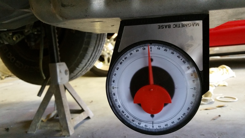
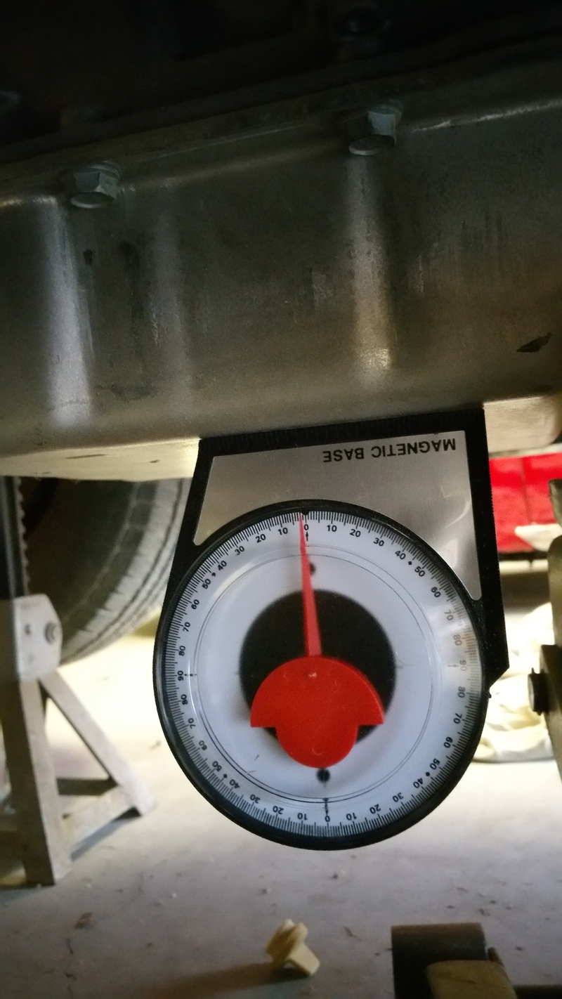
Until reading an earlier post in this thread, I had planned on measuring angle of the transmission on the bottom of the pan. So, I am assuming this is a useless measurement, but have measured there also anyway (to see what the feedback is):
The above picture is of the measurement with the transmission NOT lifted. That measurement is ~ 2.5 degrees down.
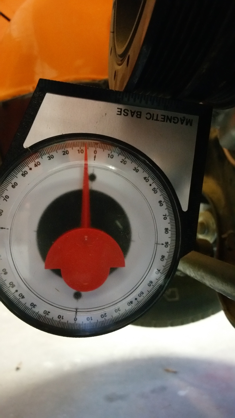
Next up is a measurement where I put the tool on the front/back lips of the crankshaft pulley. The picture below is of that measurement:
That measurement is ~6.5 degrees down. So, there is a 4 degree difference between the reading on the transmission pan and the crankshaft pulley.
Next up, transmission lifted by 1"
I only took a measurement at the pan, and at the pulley.
Below is the pan:
The measurement is a hair under 2 degrees down. That picture looks a bit off center...it could actually be 1.5 degrees down.
And finally, the measurement at the crankshaft pully with the transmission raised 1":
That measurement is a hair over 4 degrees.
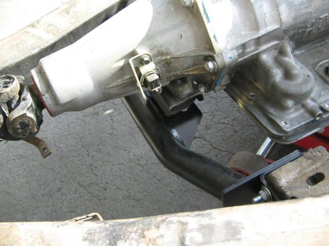
One other note: It looks like I'm going to have to have the transmission lifted at least some in order for the transmission/drive shaft yoke to clear the emergency brake mechanism.
Plus when you move the transmission up your only moving the front section of the drive shaft.
Elite 59...Forgetting that maybe I need that tranny up a bit anyway...I'm not sure I see what difference it would make on the drive shaft as to whether the motor is lower or the transmission lifted. Of course the overall geometry would change, I think: lowering frount and leaving back at same mount would effectively lower the angle at the front of the yoke (hope you can follow that thought). I'd think that raising it at the back (at the transmission that is) would have the same result.
Anyway, what I have now looks like a best possible angle of 4 degrees w/o changing motor mounts and lowering the front. From the Spice booklet:
From the book I linked:
FOR VIRTUAL VIBRATION FREE PERFORMANCE, UNIVERSAL JOINT OPERATING ANGLES SHOULD NOT BE LARGER
THAN 3 DEGREES. IF THEY ARE, MAKE SURE THEY DO NOT EXCEED THE MAXIMUM RECOMMENDED ANGLES
That quote leaves me a little confused. So where do a person get the 'MAXIMUM RECOMMENDED ANGLES' that they are referring to?
Last but not least, if I understand that document correctly, I need to have the driveshaft in and measure that to calculate the 'operating angle'. That's the important thing to all this it seems.
Measuring with Tremec app
OH, on one other note: I also tried measuring the angles with the Tremec app on my phone. But, I could measure it multiple times and get wildlyl different readings. The measurements required with this app are to calculate the 'operating angle', so I needed 3 measurements: crank, driveshaft, rear end. Not having the driveshaft installed (can't until I get one shortened), I just did erroneous measurements on the other two. I found with that app, that if I the erroneous measurements were close to the same as the crankshaft, my crankshaft measured 2-3 degrees. But if I had wildly different measurements for the other two, the crankshaft would show as 10 degrees. Makes no sense to me.
[EDIT]
Yeah, just re-read the booklet. Unless I'm misunderstanding it, The operating angle of the drive shaft is the important thing, and I won't be able to determine that until I get a drive shaft cut and installed.
I hope this helps, After leveling the frame to zero, determine the angle of the differential at the pinion yoke, not the bottom or top of the differential housing you’ll never get the correct angle. On 1958 to 64 full size chevys there shouldn't be that much off to the correct diff angle (it set at the factory) if so shim at the banana bar to achieve the correct angle. To determine the angle of the engine put your angle finder at the bottom of the starter.
I use two tools the determine the angles. The gauge angle finder from Harbor Freight like yours. I had to buy 2 because the first would stick and was a pos I also use the Craftsman Digital Torpedo Level Item # 00948295000P Model # 48295 this one is great, Magnetic with all the bells and whistles. As for the drive shaft length, (so you don’t loose time working on your 61) cut the front section yourself. Cut the welds off with a Air cut off tool, cut thru the weld at the cast end of the driveshaft. Knock out the cast end. measurer and cut to the correct length. Put the end back on and measurer again until your sure you have it correct. Make sure it's clocked right, Check all your measurements and angles on the motor. After all that, take it to your driveshaft shop and have them weld it and balanced. Oh, as for the Tremec app, read it but I don’t have a smart phone. Oh well. in my 2 cents as long as you have the Diff angle correct, the motor angle correct and the correct center Carrier Bearing height you should be ok, That’s all I could do in my 59, hope I got it right, If not it’s back to the drawing board
Being at 4 degrees, it seems that maybe I am at the MAX I should be at, and recommendation is 3 or less. I'm trying to decide if I really need to pull the engine and do the notch in the crossmember.
I did call BRP who makes the Musclerods LS conversion kits. They advertise that using their motor mounts, stands, and transmission mount that it will be at the right angle. So I called them and asked what angle their kit provided, and they said 4 degrees.

 08-12-2014, 08:14 PM