Fresh Build. Help with high MATs!!! Air/Water/Ice Intercooler


 11-03-2016, 01:00 PM
#22
TECH Enthusiast
Thread Starter

All Great input. I appreciate it fellas.
I can tell you no, I don't have actual data of the flow rate. What I can also tell you though is the return back in to the tank is like having your hose at home on full with no nozzle on it. There is, what looks to me, good flow. It's not coming out at 100psi like a jet stream, but it is moving quite a bit of water. I have -12an feed and return, with all -10an Fittings and line on the intercooler core itself. When we turn the pump on after adding ice, the intercooler itself and lines go from warm to the touch, to ice cold to touch in a matter of 5-10 seconds from the cold water flow.
I can also tell you that in 1 pass at the track, 20lbs of ice in the reservoir at the start of the pass is totally melted, and the water is chilly but not frigid when I park after the pass, so heat transfer must be occurring.
This same pump and feed/return lines were keeping the IATs totally in check on my overspun 2.9 Whipple blower without issue.
11-03-2016, 01:10 PM
#23
It's the rate the heat transfer is occurring that makes the difference though. If the water isn't cycling through fast enough to cool the core it's never going to work as it should. Might call up 417 and ask what the core is rated at in GPM. Then put a little cheapie gauge like this on the return temporarily just to see where you are at.
http://www.ebay.com/itm/Turbine-Digi...9V1Zt2&vxp=mtr
May MIC the ID of those fittings too. My AN10 stuff necks down pretty small. Also alot of the china fittings have super narrow ID's. 1/2" is really too small IMO.
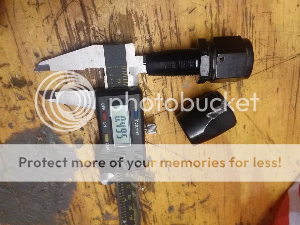
Even true AN12 hardware fittings neck down too far IMO. (not china junk this was pulled off aircraft)
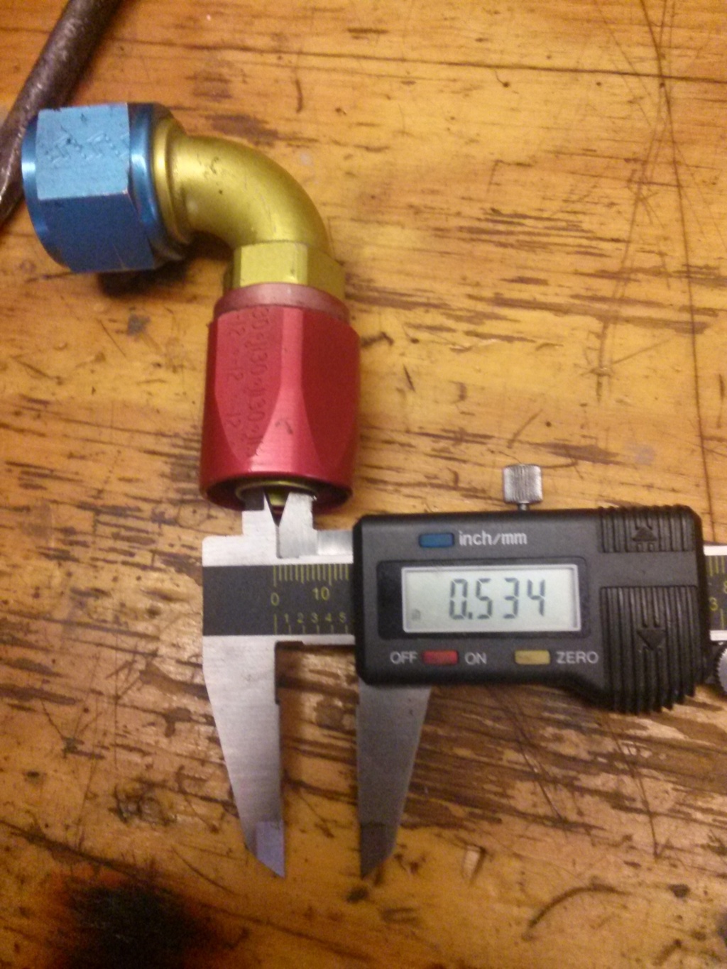
If you get true 3/4" ID fittings and hose I bet it makes a big diff. 1" would be ideal but it starts to look like bathroom plumbing under there...

http://www.ebay.com/itm/Turbine-Digi...9V1Zt2&vxp=mtr
May MIC the ID of those fittings too. My AN10 stuff necks down pretty small. Also alot of the china fittings have super narrow ID's. 1/2" is really too small IMO.
Even true AN12 hardware fittings neck down too far IMO. (not china junk this was pulled off aircraft)
If you get true 3/4" ID fittings and hose I bet it makes a big diff. 1" would be ideal but it starts to look like bathroom plumbing under there...
Last edited by Forcefed86; 11-03-2016 at 01:16 PM.
11-03-2016, 01:24 PM
#25

On top of what we talked about on the phone... im not a fan of the T fitting in the rear ports...
I would much prefer there be a -16 to -12 Y fitting and then equal length legs ran to each port on the cooler. at least on the feed side.
I would much prefer there be a -16 to -12 Y fitting and then equal length legs ran to each port on the cooler. at least on the feed side.
11-03-2016, 01:51 PM
#27
Those IAT sensors are done around 250. Hot cars I worked on peaked the sensor right around the 1/8th, and those are twin setups.
Can use this calculator for a good guess.
http://www.stealth316.com/2-turbotemp.htm
Can use this calculator for a good guess.
http://www.stealth316.com/2-turbotemp.htm
11-03-2016, 02:08 PM
#28
TECH Enthusiast
Thread Starter
I appreciate it fellas. This is all definitely a learning curve for me and I can't wait to get it totally dialed as it's already pretty rowdy when it's running too hot on low boost!!!
11-03-2016, 02:28 PM
#29
Did any of the plumbing change from when you were on the whipple? What turbos?
When you start getting to the outsides of a compressor map, it seems like turbos will start making alot of hot air, but i think you said you were down pretty far on boost.
PS- setup looks great and 139 is a solid *** start for a 4000lb car!!
When you start getting to the outsides of a compressor map, it seems like turbos will start making alot of hot air, but i think you said you were down pretty far on boost.
PS- setup looks great and 139 is a solid *** start for a 4000lb car!!
11-03-2016, 02:49 PM
#30
TECH Enthusiast
Thread Starter
The 3/4" feed and return did not change. Those were mounted to the IC of the blower and now act as my feed/return on this combo.
turbo is a billet S484, so it's not stressing at all yet.
and thanks man!!! i'm really looking forward to pushing it further once I get this sorted!
turbo is a billet S484, so it's not stressing at all yet.
and thanks man!!! i'm really looking forward to pushing it further once I get this sorted!
11-03-2016, 02:51 PM
#31
9 Second Club

The sensor is on the bottom side of an iced intercooler though. If it�s not picking up heat form the manifold, at low pressure/flow with 32* ice water being pumped through the IC at full tilt should easily cool ambient air down to 60* form ambient I�d think. Especially if the intake was relatively cool before a run at the drag strip.
11-03-2016, 03:34 PM
#32

you need more flow through the core.
I'm doing my entire A2W system out of -16 fittings and 1" tubing and hoping it will work.
Also, the brick you have is a little thin- so this is going to hurt you as well. Much heat exchanger efficiency comes from thickness- but you can't change this.
I would increase flow as much as possible. Also, you may have good flow sitting still, but loosing it during the pass.
See if you can put a flow meter in line and datalog it. This is actually a good idea and something I will look into doing as well. Surely would help to trouble shoot. Also gives me some engineering data to judge how well the system is working.
temp sensors pre and post the brick on the air and water side would be nice as well.
11-03-2016, 05:01 PM
#33
TECH Enthusiast
Thread Starter
you need more flow through the core.
I'm doing my entire A2W system out of -16 fittings and 1" tubing and hoping it will work.
Also, the brick you have is a little thin- so this is going to hurt you as well. Much heat exchanger efficiency comes from thickness- but you can't change this.
I would increase flow as much as possible. Also, you may have good flow sitting still, but loosing it during the pass.
See if you can put a flow meter in line and datalog it. This is actually a good idea and something I will look into doing as well. Surely would help to trouble shoot. Also gives me some engineering data to judge how well the system is working.
temp sensors pre and post the brick on the air and water side would be nice as well.
I'm doing my entire A2W system out of -16 fittings and 1" tubing and hoping it will work.
Also, the brick you have is a little thin- so this is going to hurt you as well. Much heat exchanger efficiency comes from thickness- but you can't change this.
I would increase flow as much as possible. Also, you may have good flow sitting still, but loosing it during the pass.
See if you can put a flow meter in line and datalog it. This is actually a good idea and something I will look into doing as well. Surely would help to trouble shoot. Also gives me some engineering data to judge how well the system is working.
temp sensors pre and post the brick on the air and water side would be nice as well.
11-03-2016, 05:08 PM
#34
OP, also you should have some kind of master switch for turning your water pump on and off. Because after your run, like literally as you are decelerating after the beams, turn off your water pump. That helps save most of the ice in your tank. Then turn it on right after the burnout, and as you are staging.
11-04-2016, 12:25 PM
#36
OP, also you should have some kind of master switch for turning your water pump on and off. Because after your run, like literally as you are decelerating after the beams, turn off your water pump. That helps save most of the ice in your tank. Then turn it on right after the burnout, and as you are staging.

The lowest hanging fruit is what LJMSJohn said about lowering intake air charge, maybe by removing a headlight or something?? and increasing the flow through the brick.
I'm going to do a calc in a few minutes to estimate the head loss on the water pressure at the brick assuming the tank and pump are in the rear of the car. I'll post up in a few.
11-04-2016, 12:30 PM
#37
Makes me want to build a scoop sort of tube for my setup. You can kind of see how mine is positioned in my sig pic. Of course, I would love a forward facing turbo setup, but that will have to be for turbo build v4.0. lol Currently trying to finish up v3.0. It never stops. haha
11-04-2016, 12:55 PM
#38
Laugh all you want but 5" HVAC alum dryer duct is awesome. Light weight and super strong once you fiberglass it. The joints pull apart so you can add or remove as many links as you want. Twists and turns anyway you need and it's a pretty tight radius. If you do a good glass job and sand/paint it can look nice as well.
I could literally stand on it once the resin set.
I could literally stand on it once the resin set.