When you click on links to various merchants on this site and make a purchase, this can result in this site earning a commission. Affiliate programs and affiliations include, but are not limited to, the eBay Partner Network.
Well this fuel system is finally up and running, no leaks. One thing I may add is a check valve in the feed line, to reduce fuel pressure bleed off when the car is off for a few days. Over night I have little to no fuel pressure, a few hours it drops like from the 60psi set point back down to about 30 psi. A single prime of the pump picks the pressure back up fine after a few hours, but after a day or 2 it cranks a little more than I'd like before it starts.
I need to do some tuning of the car on the street, to get things dialed in closer, before I take it to a dyno. My intent is to rent dyno time to get the final tune done, but I want to be fairly close before I put it on the dyno, so it takes less time, and costs less money. I'll use part throttle pulls, and some limited full throttle pulls on the street to dial in the VE table close, close enough that I'll be comfortable with flogging it on a dyno to look for optimum performance.
Well I finally got this thing up and running, and have the tune dialed in decently. I took it over to Jessie Coulter's shop red91z. He was fantastic to work with, very experienced guy, and willing to put up with all my questions.
I think it looks great with the 5th gen style grill on it, and it lets lots of air through to the intercooler.
I'm pleased with the graph too. I ended up going with E70 as the fuel source. There are various reasons I went with this rather than E85. One is that in the winter time E85 is not 85% ethanol typically they blend more gas into it. If you tune a car for E70 you don't need to worry about it dropping down in the winter. When you have true E85 you mix 1 gallon of E10 to 4 gallons of E85 to get E70. What I do is put in about 8 gallon of E85, test it for content, whip out my cell phone for the calculator, and calculate how much 93 octane I have to pump in to end up with E70. If it tests 85 I add 2 gallons, if it tests 80, I add 1.33 gallons, if it were to test 75 I would need to add 0.66 gallons. If it tests 70 then I just fill up the tank with it. If it tests a little lower like E65, it will just run a little rich, really not a big deal, but I've never seen it test below about 72 or 73. In reality a variance of up to 10 points is acceptable, the long term fuel trims will take care of it. Thinking about it, all of our 4th gen cars, and all cars of that area, come from the factory set up to run zero ethanol, and they all run fine on E10.
714hp SAE at the tires, and that is with a conservative tune. There is probably another 100 HP left it in. That was at 15 psi, 19 degrees of timing through an unlocked automatic, with a muffler on the car. I could put another couple lbs of boost to it before I run out of map sensor, and maybe another degree or 2 of timing to it. As well locking the converter is worth about 10% based upon my previous experience. This is not about being a dyno queen though. I just want it to run fast. Needless to say, the fuel system functioned well. It was basically invisible, when fuel was needed it was there. Honestly it was easier to tune than I thought it would be.
QUOTE=ScottyBG;19482637]Well the new wiring system I got is the universal dual pump harness set up. The components installed include:
UDPH 005 the universal wiring harness
IDPH-F98 the intermediate harness for a '98 Fbody
and the HIH-001 the hobbs switch interface harness
All 3 of these components are required to make up a complete plug and play system.
This will replace the 2 harnesses that are currently on the car. Both of them Hotwire Kits, one for each pump.
Again the reason for doing this are simplifying to a much neater, more OEM/professional type of an install. This will also be a solution which is vapor proof, and all of the EVAP system is being maintained on the car, with full functionality.
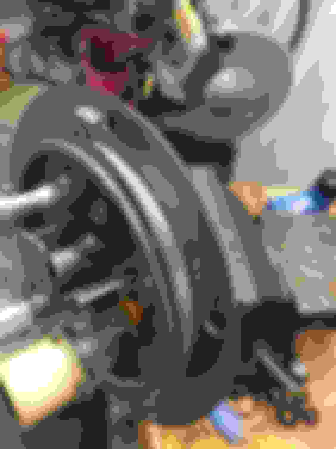
Well to begin I needed to remove the wiring components, starting with the fuel pump assembly.
I started with cutting off the connectors I put on the ends of the individual fuel pump harnesses and run out through the grommet. Then onto removing the factory bulk head from the tank.
To remove the factory bulk head, you will need to start by removing the lock which holds the connector inside the tank to the bulk head, then pull the connector off.
I just twisted the ring off the bottom of it with some pliers. It did destroy it, but I don't think these things are really reusable. A new lock ring would be required to do so.
Next I needed to install the leads from the float level sending unit into the new wiring harness that goes inside the tank, that comes in the UDP 005 kit.
There are 2 areas in the connector that goes on the bulk head that are open, so these correspond to the areas that were used in my factory bulk head. So I transferred the connectors over into their same location on the new harness.
After that I put the lock in the connector and it is ready to go on the new bulkhead once it is mounted.
Next I need to plug the hole that I had made which I had the grommet through. I chose to do this with hex cap screw with an O-ring off an old fuel injector. It squeezed in there quite well, and I feel it is sealed up vapor tight.
You shouldn't have to seal this hole up, unless yours has been drilled for DIY dual fuel pumps like mine was.
Next onto installing the new bulk head that is included in the kit. The reason for the bulk head change is this one is rated for higher amperage than the factory one, to handle the increased current draw of the high volume aftermarket pumps. This is actually part of the intermediate F98 kit for 98 Fbodies. I believe there is a different bulk head in the 99-02 kits.
The bulk head presses into a ring on the underside like the factory one does. There probably is a special tool to put these together, but what I did worked well and was easy. I used a 7/16" socket and a wood clamp top press the ring onto the underside of the bulk head, I just kept screwing it until the bulkhead was well seated on its o-ring seal, and didn't wiggle anymore. Then I connected the in tank wiring harness to the bulkhead.
Then in needed to drill a 3/16 hole for the ground post to go through.
After that I installed the grounding post and attached the ground for in tank portion of the wiring harness, then it was done. This is how it looked with the ground post it, and both the pumps, and the sending unit wired in.
The bulk heads both have 4 connectors. The original factory set up used 2 for the level sending unit, one for the power feed to the pump and one for a negative lead, to the pump. The way this new bulk head works is that it uses 2 for the level sender, and 2 positives, one for each pump. The pumps both get their grounds, or negative side through the grounding lug mounted beside the bulkhead. The fuel pump assembly is now complete and ready to go back in the car.
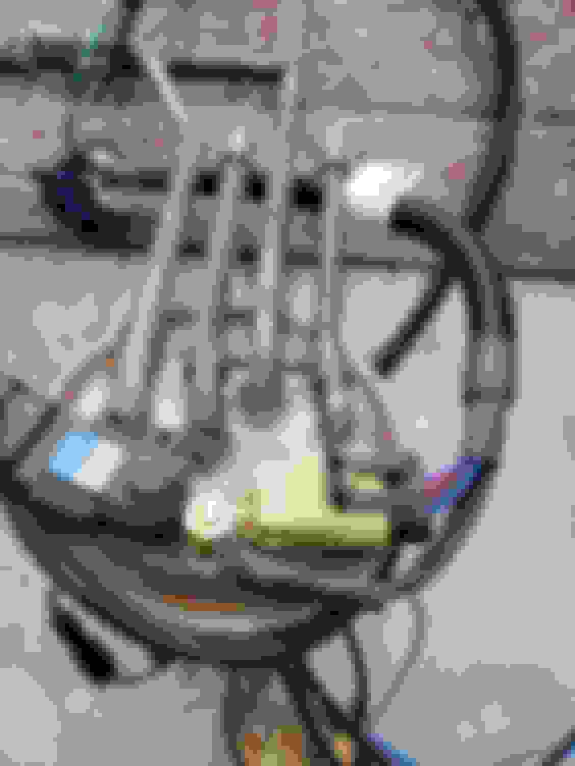
Next is on to wiring in the main wiring harness, I laid it out on the garage floor to get a look at it and get a vision of how I would install it.
It has a few ring connectors, and 2 fuses, one for each pump up at the front' as well this is where the hobbs switch harness connects to either the red or the blue circuit up at the front of the car, under hood. Both of the relays go at the back of the car, like where an original hotwire kit goes, if you have had one of those before. At the back end of the main universal harness it has a large round weatherproof connector where it interfaces with the model specific intermediate harnesses.
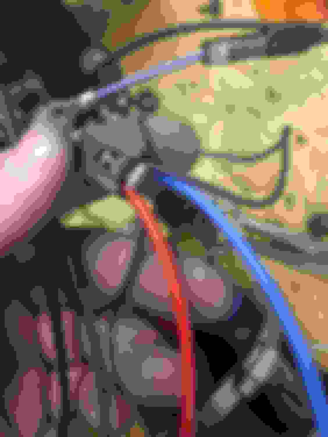
Well lets get started installing this main harness. We need to go to where the factory fuel pump circuit comes out on the body. This connector is found under the body, just above where the brake hoses that run to the rear axed attach to the body. My install is a little different because I had to start by removing my hot wire which was already connected here. Here is a photo of the connector I'm referring to.
This connector is labeled with letters A through H. The connectors we are concerned with are.
A- purple level sender wire
B - gray factory pump positive feed
C - black factory pump ground
F - Black stripe wire for level sender
The other 4 connectors we are not concerned with, 3 of them are for the Evap system, and 1 is not used, just leave them alone.
We do need to remove the factory wires, or the wires from the original hot wire kit (which might be in B and C if you have a hotwire) from the 4 locations mentioned above, A,B,C,F. See photo.
I then went ahead an removed these 4 wires from the factory harness. The intermediate harness will now be performing the duties of these 4 wires, so they are no longer needed. You should just have the 3 wires for the pressure sensor for the evap system left in the harness that runs from this block to the top of the tank.
Continued next post since this is getting pretty long.[/QUOTE]
What did you do with the purple ground wire on the intermediate harness in the fuel bucket?
What did you do with the purple ground wire on the intermediate harness in the fuel bucket?
Honestly I didn't know why there was a 4th ground wire there.
As you can see there are 3 black grounds. 2 of them are for the pumps, 1 for each, and the third black ground wire is to ground bottom segment of the metal hangar. The purpose of this is to make sure both halves of the metal hanger are at exactly the same potential, because if they weren't there could be current traveling through the hinge. That is how the factory one is set up as well, that is why there is that little tab there to attach too. This common grounding all to that same lug, also ensures the grounded portion of the pump is at exactly the same potential as the hangar. This is also a secondary measure to prevent any type of static charge from building up in the fuel. This is all really just for safety, as any remote chance of spark arcing in a fuel tank must be eliminated. I just removed that Purple section and tucked/tied the other portion up near the top of the hanger where it wasn't in the way.
I though about removing it completely from the spade at the grounding lug, then I thought, maybe someday I may use that as a ground for a 3rd pump if ever I decided to go that way. I have seen some others have added a 3rd pump. I'm guessing since these parts are somewhat universal, they may have put it there as a possible future expansion for something else?
Good catch, I probably should have written something up about that in the original post. Good to know people are actually reading what I had written.
What size is the fuel tube is it their 8mm?? I am in need of one mine is for a 99 but I cant imagine it would be different.. Thanks in advance and nice numbers of the car...
The fuel tube I used was 8mm x 140mm. You will need to expand 1 end to 3/8" to fit over the dual pump coupler. The best way I have found to do this was to heat the tube with my heat gun, the same one I use for heating shrink wrap on wiring, then threading a 3/8" fine thread bolt into the end of the tube that I've heated with the heat gun. I let it cool off with the bolt in there, then I backed the bolt out. That stretched it out.
I can't believe they don't include that in the kit..I thought you found one expanded already?m Thanks for the reply...
Racetronix has the capability to expand them, they are not on their website, but I was communicating with them through Email, and requested that they expand one for me. It would be "really really great" to quote our president, if they just put one in the kit. There was no extra charge for this though. I'd be willing to pay an extra buck or 2 to save needing to expand it myself. I'd heard of another guy that Racetronix had done this for as well. I don't know why they don't add them to their website as a separate item, so you can just put them in the cart that way. It is really quite easy to do it using the method I described though. The one on my car is expanded by Racetronix, but I did one for another guy the way I mentioned, with the 3/8 hex cap bolt, and my heat gun.
I feel we need to clear up a few things about the OPs original post and parts list. We have had quite a few guys try to follow this setup and have gone terribly wrong or had to order more parts later on.
First off, yes, racetronix offers both a dual 255 and dual 340 and now a dual 450 setup. These contain just the pump and brackets for them. Any external harnesses have to be purchased separate BUT we are bundling them together so its easier to buy everything at once.
Second, using 2 hotwire harnesses is one way to make it work BUT the biggest issue is the bulkhead connector at the fuel pump. The std square connector can only support 15 to 20 amps max. That is why it either melts down itself, or the connector, or burns the pumps up prematurely. That is the reason all new pump modules come with th flat/flat bladed bulkhead now. Those are nominally rated at 30 to 40 amps. That is also why all the new racetronix hotwire kits come with the flat connector on their harness AND the new bulkhead connector. It allows more current to pass to the pumps, builds less heat, and keeps the pumps happy and living a long life.
Obviously you can cut into the module and just stuff the wires from buying 2 reg hot wire kits and plumb them to the pumps themselves, but then you are forced to use some sort of fuel resistant epoxy etc.
Racetronix has everything thought out from front to rear and is almost 100% plug an play. The actual dual pump harnesses are a little more expensive but are designed specifically for this use and current load etc. They are what we will always recommend for these dual pumps. They are engineered to work and we have had no issues with that.
Im not trying to **** on the parade but the wiring issue has to be addressed so that the money you spend is spent in the right places and for the right parts. Racetronix does not proactively address this, but they are busy with many things. We try to offer the best tech support we can and the quickest and most concise answers.
We are adding complete package dual pump setups both with and without their Hobbs interface setups to give you a variety of ways to get them set up. When they are done, we can update this thread with the right pns. We are trying to keep all of these on hand, and they do sell out quickly.
If you have any more questions, call, pm, email us!!
Just want to say nice write up!
I just ordered the 98 duel 340 racetronic kit from ws6store, and im pretty intuitive, but was a little disapointed that this kit didnt come with the detailed instructions simualr to the single 98 hotwire kit i got back in 2013 with the older kit, but its pretty easy to figure out except for a couple connectors that im not sure what they were for or didnt have another end of a plug. I see that they supple the massive bulkhead connector for the hat, but theres nothing that plug directly into it in the kit. Theres a bit of extra stuff im not sure if i need or not too.
I guess with the 98 dual 340 kit, the hobbs switch harness kit doesnt come with it? -to answer this, I got the kit that didn't, so pay attention to which one you get when you order.
i also have a question is what does that large purple wire with the ring terminal inside the tank off the harness go too? I didnt catch what that hooks too? -Firgured this out. its the grounding for the sender. somewhat redundant, and OP made a mention to it as well, I just skimmed too fast.
also, i see you hooked your positive connectors to the positive lug on the driver side, so i do not need to run the main harness to the alternator? -this harness seems like it was made to be ran in this configuration. that or when the alternator is in the low driver side stock configuration, as the positive leads and the negative leads are pretty close to eachother. without yanking the harness apart, I dont thing it would run easily in the passenger high mount position with out yanking the ground lead some.
Last edited by JoshuaGrooms83; 12-04-2020 at 05:53 PM.
Reason: Found some answers for the good of the group.
ok i got it! I answered a couple of my own questions lol I just had to sit back and kinda think my way thru the process. the biggest help was which wires to pull out of the stock harness.
I'm not taking anything away from the original content, as this was absolutely fantastic!! I thought that I might add some additional pictures for reference as well mention some key points to remember. more pictures the better i always say!
i did nearly exactly as he did, except i didn't do a DIY twin pump, i went from a old hotwire kit directly to a dual 340 pump kit from racetronic. i ditched my old harness because I couldn't figure out why my pump wasnt running on the hotwire. Turns out, I might have shorted the old 98 hotwire relay with a walbro 450.
Top of the hat with everything fully connected after drilling the hole. its actually not bad. I would say though, try to drill the hole a little closer to the outside lip where you see where I have it. its not bad, but the ground lug washer and retaining clip are a bit close and this might be why I was fighting to get it on the rest of the way.
all wiring attached to the hat before putting it into position.
this helped me to kind of visualize where everything needed to go The purple wire is an additional ground. took me a sec to figure out how it connects. so the eyelet is actually grounding the fuel level sensor, and then the other side goes into the suppled connector. with this, pay attention to the connector under the hat and on top, cause until you get the holding clip in place, its easy to forget which one is which. you do have to repin one of the purple wires see here.
we gotta remember, although this is a plug and play, there are some parts that are included that are partially "universal" in nature so its not exact PnP but its 98% there. lol see what i did there 😉
getting the clip into place is an absolute nightmare without a clamp!! some carefully placed punch, and hamme with slight, careful and deliberate taps get it in there.
another look at all the grounds on the new groud lug. its a tight fit. make sure you orientate it so it doesnt pinch or protrude into the lids seating position. another view of the pump wiring. fortunatly 8 managed to get the tube off the 450 i had in ther before. it expanded the hose enough that i didnt need to heat the tube racetronic supplied. Also, some slight clipping on the white plastic part is required to fit the pumps in there as I did. inclaped mine from the back of the pump bracket to the stock sending arm. the intermediate harness up top. it actually fits through without dropping the tank. As big as it is, as long as your trap door is cut to the right dimensions, mentioned in a few threads here, you should be able to slide it. it works best sideways and towards the right. I managed to do all of this without any help.
here are those wires he mentions up top
A Purple
B Gray
C Black
the rest leave alone as they begin to fit into place All button up up top! Heres what it can look like with factory lines. I know i know, but ill run 8an feeds later. i already have a 5/16 hard line for a true return so im partially there but eventually ill run more with lock fittings but for now, the stocks work. close up of the top finshed product. under the car is pretty simple. everything goes as he says. i used some self tappers on the relays and used the existing bolt for the brake bracket for the grounds heres what the stock connector should look like when your done this is one of the things i had questions ok... I got this in my kit, im not sure what it is for, maybe someone can clarify this for later. my car runs without it so i guess i dont need it?
Last edited by JoshuaGrooms83; 12-04-2020 at 06:08 PM.
We can and do offer this modification to brand new gm 98 modules and even the LT Modules as well. Single 340, single hellcat, and duals. It would be a complete plug and play on that point with the only issue being running the lines for their fuel line kit etc.
Obviously it would be more $$ than just the diy kit, but you're literally getting all brand new parts all engineered to work and drop in.
The reason we cannot offer instructions are due to the many different aftermarket replacement modules for the 98s. They are all Slightly different. Ive counted at least 10 different styles. So even a loose guideline is hard to do.
Absolutly, and when i look back on it, it makes sense that it doesnt come with instructions specifically for our cars, BUT! if you happen to have the old instructions on the single hotwire kit, it does give you a bit of guidance on things like the pins and pump configurations, which i still had from when i installed mine. Overall its litterally nearly all there, with the customer just needing be a bit more savvy on automotive fuel systems and wiring practices.
I was so happy when it fired right up too!
 12-29-2016, 08:09 PM


 allons, if it tests 80, I add 1.33 gallons, if it were to test 75 I would need to add 0.66 gallons. If it tests 70 then I just fill up the tank with it. If it tests a little lower like E65, it will just run a little rich, really not a big deal, but I've never seen it test below about 72 or 73. In reality a variance of up to 10 points is acceptable, the long term fuel trims will take care of it. Thinking about it, all of our 4th gen cars, and all cars of that area, come from the factory set up to run zero ethanol, and they all run fine on E10.