
TPS Replacement? Pics

 04-03-2014, 10:05 PM
#3

Engine Controls
DTC P0120
CIRCUIT DESCRIPTION
The throttle position (TP) sensor incorporates 2 ratiometric TP sensors into one housing. TP sensor 1 and TP sensor 2 each have a 5-volt reference circuit supplied by the throttle actuator control (TAC) module. The TAC module supplies each TP sensor with a low reference circuit. Each TP sensor supplies the TAC module with a signal voltage that is proportional to the throttle blade position. The TP signal voltages are opposite from one another. TP sensor 1 is pulled up to reference voltage as the throttle blade is opened. The TP sensor 2 is pulled down to low reference as the throttle blade is opened. The TP sensor 1 and the accelerator pedal position (APP) sensor 1 share a 5-volt reference circuit that is bussed within the TAC module. The TP sensor 2 and the APP sensor 2 share a 5-volt reference circuit that is also bussed within the TAC module. The APP sensor 3 has a dedicated 5-volt reference circuit.
When this DTC sets, the Reduced Engine Power indicator will be displayed.
This DTC incorporates 3 different diagnostic tests:
TP sensor 1 signal circuit voltage out of range
Throttle blade minimum position for the TP sensor 1 out of range
5-volt reference of the TP sensor 1 voltage out of range
DTC DESCRIPTOR
This diagnostic procedure supports the following DTC:
DTC P0120 Throttle Position (TP) Sensor 1 Circuit
CONDITIONS FOR RUNNING THE DTC
DTCs P2108 or U0107 are not set.
The ignition switch is in the crank or in the run position.
The ignition voltage greater than 5.23 volts .
The TP sensor 1 signal voltage test runs continuously once the above conditions are met.
The throttle blade minimum position for the TP sensor 1 test runs once when the ignition is turned ON and the above conditions are met.
The 5-volt reference of the TP sensor 1 voltage test runs continuously once the above conditions are met.
CONDITIONS FOR SETTING THE DTC
TP sensor 1 signal voltage is less than 0.38 volts or more than 4.50 volts for more than 0.1 second .OR
The TP sensor 1 minimum throttle blade position is less than 0.38 volts or more than 0.71 volts for less than 1 second .OR
The 5-volt reference circuit of the TP sensor 1 is shorted to ground for more than 0.01 second .OR
The 5-volt reference circuit of the TP sensor 1 is less than 4.54 volts or more than 5.21 volts for more than 1 second .
ACTION TAKEN WHEN THE DTC SETS
The control module illuminates the malfunction indicator lamp (MIL) when the diagnostic runs and fails.
The control module records the operating conditions at the time the diagnostic fails. The control module stores this information in the Freeze Frame and/or the Failure Records.
The control module commands the TAC system to operate in the Reduced Engine Power mode.
A message center or an indicator displays Reduced Engine Power.
Under certain conditions the control module commands the engine OFF.
CONDITIONS FOR CLEARING THE MIL/DTC
The control module turns OFF the malfunction indicator lamp (MIL) after 3 consecutive ignition cycles that the diagnostic runs and does not fail.
A current DTC, Last Test Failed, clears when the diagnostic runs and passes.
A history DTC clears after 40 consecutive warm-up cycles, if no failures are reported by this or any other emission related diagnostic.
Clear the MIL and the DTC with a scan tool.
DIAGNOSTIC AIDS
Inspect the TAC module connectors for signs of water intrusion. When water intrusion occurs, multiple DTCs could be set with no DTC circuit or component conditions found during diagnostic testing.
When the TAC module detects a condition within the TAC system, more than one TAC system related DTC may set. This is due to the many redundant tests that run continuously on this system. Locating and repairing 1 individual condition may correct more than 1 DTC. Disconnecting the components during testing may set additional DTCs. Keep this in mind when reviewing the Capture info.
If this DTC is determined to be intermittent, refer to Intermittent Conditions. See: Powertrain Management\Computers and Control Systems\Testing and Inspection\Initial Inspection and Diagnostic Overview\Diagnostic Strategies\Intermittent Conditions
TEST DESCRIPTION
Steps 1-7
Steps 8-17
Steps 18-28
Steps 29-33
The number below refers to the step number on the diagnostic table.
When the TAC module detects a condition within the TAC System, more than one TAC System related DTC may set. This is due to the many redundant tests that run continuously on this system. Locating and repairing 1 individual condition may correct more than 1 DTC. Disconnecting the components during testing may set additional DTCs. Keep this in mind when reviewing the Capture Info.
04-03-2014, 10:06 PM
#4
TECH Resident

Join Date: Aug 2010
Posts: 756
Likes: 0
Received 0 Likes
on
0 Posts

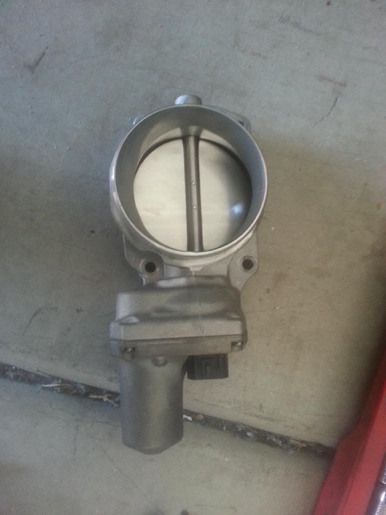
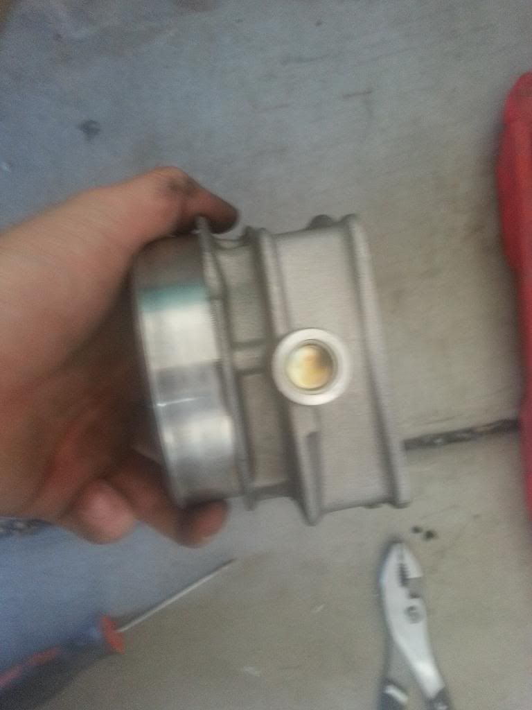
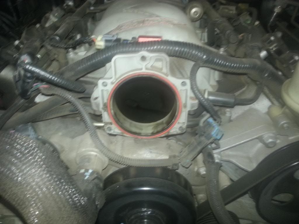
I found the problem looks like you have a fast intake manifold. Send me the fast one and ill send you the ls2 one with a working tb 
You just replace the whole throttle body if the tps goes bad.
You just replace the whole throttle body if the tps goes bad.
04-03-2014, 10:07 PM
#5
Transmission Controls
DTC P0120
Circuit Description
The Engine Control Module (ECM) sends accelerator pedal position data to the Transmission Control Module (TCM) . The TCM uses this data to modify shift speeds. The data is sent to the TCM through a communication network called the Controller Area Network (CAN) . Two circuits are used to communicate CAN data between the ECM and TCM. A fault in the CAN will not cause DTC P0120 to set by itself. If a CAN fault occurs, other DTCs will set before DTC P0120.
When the TCM receives invalid accelerator pedal data from the ECM, then DTC P0120 will set. DTC P0120 is a type B DTC.
DTC Descriptor
This diagnostic procedure supports the following DTC:
DTC P0120 Throttle Position (TP) Sensor Circuit
Conditions for Running the DTC
The engine run time is greater than 5 seconds.
No other CAN errors are present.
Conditions for Setting the DTC
The TCM receives no valid accelerator pedal data from the ECM for 2 seconds.
Action Taken When the DTC Sets
The TCM requests the ECM to illuminate the Malfunction Indicator Lamp (MIL) during the second consecutive trip in which the Conditions for Setting the DTC are met.
The TCM uses the ECM default accelerator pedal value for determining shift speeds.
The TCM turns off the pressure control solenoid. When the pressure control solenoid is off, line pressure is at maximum.
The TCM freezes transmission adaptive functions.
The TCM disables the TCC.
At the time of the first failure, the TCM records the operating conditions when the Conditions for Setting the DTC are met. The TCM stores this information as a Failure Record.
At the time of the second failure, the ECM records the operating conditions when the Conditions for Setting the DTC are met. The ECM stores this information as a Freeze Frame.
The TCM stores DTC P0120 in TCM history.
Conditions for Clearing the DTC
The ECM turns OFF the MIL after the sixth consecutive drive trip in which the TCM does not send a MIL illumination request.
A scan tool can clear the DTC.
The TCM clears the DTC from TCM history if the vehicle completes 40 warm-up cycles without a non emission related diagnostic fault occurring.
The TCM cancels the DTC default actions when the ignition is OFF long enough in order to power down the TCM.
04-03-2014, 10:09 PM
#6
P2135
DTC P2135
CIRCUIT DESCRIPTION
The throttle position (TP) sensor incorporates 2 ratiometric TP sensors into one housing. TP sensor 1 and TP sensor 2 each have a 5-volt reference circuit supplied by the throttle actuator control (TAC) module. The TAC module supplies each TP sensor with a low reference circuit. Each TP sensor supplies the TAC module with a signal voltage that is proportional to the throttle blade position. The TP signal voltages are opposite from one another. TP sensor 1 is pulled up to reference voltage as the throttle blade is opened. The TP sensor 2 is pulled down to low reference as the throttle blade is opened. The TP sensor 1 and the accelerator pedal position (APP) sensor 1 share a 5-volt reference circuit that is bussed within the TAC module. The TP sensor 2 and APP sensor 2 share a 5-volt reference circuit that is also bussed within the TAC module. The APP sensor 3 has a dedicated 5-volt reference circuit.
When this DTC sets, the Reduced Engine Power indicator will be displayed.
This DTC incorporates 3 different diagnostic tests:
TP sensor 1 and TP sensor 2 correlation
Throttle blade minimum position correlation between the TP sensor 1 and TP sensor 2
TP sensor 1 signal shorted to a 5-volt reference, ground, or the TP sensor 2 signal circuit
If the PCM detects that one or more of the TP sensor 1 tests are out of range, DTC P2135 sets.
DTC DESCRIPTOR
This diagnostic procedure supports the following DTC:
DTC P2135 Throttle Position (TP) Sensor 1-2 Correlation
CONDITIONS FOR RUNNING THE DTC
DTCs P2108 or U0107 are not set.
The ignition switch is in the crank or run position.
The ignition voltage is greater than 5.23 volts .
The TP sensor 1 to TP sensor 2 correlation test runs continuously.
The throttle blade minimum position correlation test runs once after the ignition is turned ON.
The TP sensor 1 signal circuit short tests runs continuously.
CONDITIONS FOR SETTING THE DTC
The TP sensor 1 to TP sensor 2 correlation error is more than 6 percent for more than _____ seconds.OR
The PCM detects a short on the TP sensor 1 signal circuit for more than _____seconds.
ACTION TAKEN WHEN THE DTC SETS
The control module illuminates the malfunction indicator lamp (MIL) when the diagnostic runs and fails.
The control module records the operating conditions at the time the diagnostic fails. The control module stores this information in the Freeze Frame and/or the Failure Records.
The control module commands the TAC system to operate in the Reduced Engine Power mode.
A message center or an indicator displays Reduced Engine Power.
Under certain conditions the control module commands the engine OFF.
CONDITIONS FOR CLEARING THE MIL/DTC
The control module turns OFF the malfunction indicator lamp (MIL) after 3 consecutive ignition cycles that the diagnostic runs and does not fail.
A current DTC, Last Test Failed, clears when the diagnostic runs and passes.
A history DTC clears after 40 consecutive warm-up cycles, if no failures are reported by this or any other emission related diagnostic.
Clear the MIL and the DTC with a scan tool.
DIAGNOSTIC AIDS
Inspect the TAC module connectors for signs of water intrusion. When water intrusion occurs, multiple DTCs could be set with no DTC circuit or component conditions found during diagnostic testing.
When the TAC module detects a condition within the TAC system, more than 1 TAC system related DTC may set. This is due to the many redundant tests that run continuously on this system. Locating and repairing 1 individual condition may correct more than 1 DTC. Disconnecting components during testing may set additional DTCs. Keep this in mind when reviewing the Capture Info.
If this DTC is determined to be intermittent, refer to Intermittent Conditions. See: Powertrain Management\Computers and Control Systems\Testing and Inspection\Initial Inspection and Diagnostic Overview\Diagnostic Strategies\Intermittent Conditions
TEST DESCRIPTION
Steps 1-13
Steps 14-21
The numbers below refer to the step numbers on the diagnostic table.
When the TAC module detects a condition within the TAC system, more than 1 TAC system related DTC may set. This is due to the many redundant tests that run continuously on this system. Locating and repairing 1 individual condition may correct more than 1 DTC. Disconnecting components during testing may set additional DTCs. Keep this in mind when reviewing the Capture Info.