
Wiring up underhood fuse block
 06-08-2008, 07:08 PM
#1
Teching In
Thread Starter
iTrader: (1)

Join Date: Nov 2005
Location: Holly, MI
Posts: 49
Likes: 0
Received 0 Likes
on
0 Posts
I have read through as many posts as I can find on wiring up my conversion. Thanks to the information I found here, I think I have the engine/trans wiring all set. However, I want to make sure I am supplying power to the fuseblock correctly. I have a 5.3L engine and 4L60E using a stock 99 truck wiring harness and a 2000 truck underhood fuseblock. Can someone confirm where the power connections go on the fuseblock itself? Below is a picture of the fuseblock I have. The cable on the upper left is black. I normally associate black with ground. Is this ground or the main power from the battery? What about the two posts on the upper left and right?
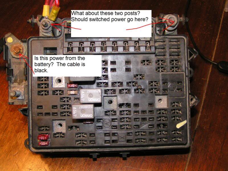
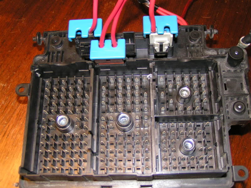
Also, what are the connections on the back of the fuseblock for? Just to clarify, the ones with the red wires coming from them.
Thanks for the help.
Ken
Also, what are the connections on the back of the fuseblock for? Just to clarify, the ones with the red wires coming from them.
Thanks for the help.
Ken
 06-08-2008, 07:29 PM
#2
Launching!
iTrader: (10)

Join Date: May 2008
Location: Omaha, Ne
Posts: 206
Likes: 0
Received 0 Likes
on
0 Posts
Well when i did my swap i used the fise block also. the connector on the left, the u said is black is the constant 12v power. the blue plugs with red wires i cant remember what they are but probaly not important, as i didnt use them. The other prongs on the top of the block were the connector are cut im unsure of. I didnt use them, but they could be 12v power from the main feed, but im not posative, as i never have tested nor use it.
06-09-2008, 12:55 PM
#3
Teching In
Thread Starter
iTrader: (1)
Join Date: Nov 2005
Location: Holly, MI
Posts: 49
Likes: 0
Received 0 Likes
on
0 Posts
Thanks for the reply. Where did you run switched 12V to? From the threads I saw, I need to connect 3 wires: 12V constant (which looks to be the big lug on the upper left), 12V switched, and the starter wire (I have that covered).
Anyone else using the fuse block?
Thanks again.
Ken
Anyone else using the fuse block?
Thanks again.
Ken
06-09-2008, 10:31 PM
#4

Does this help?
C1 connector (GM designation) (light grey color) contains the starter solenoid wire, position C10, purple with white trace. Connect this to the wire that went to your old starter solenoid. Also, A9, pink, is switched ignition return from the ignition switch. Connect this to the circuit that used to power the ignition coil.
C2 connector black Transmission power is supplied from socket F2 on connector C2 of the under hood fuse block. In a round about way that power comes from the in cab fuse block. Remove that socket from connector C2 and move it to pocket B9 on connector C2. B9 is fused by fuse #24 (ETC Fuse, not normally used). That fuse, and INJA, INJB and ECM1, run off of the same relay (IGN1 Relay), and therefore is switched 12V
C3 connector( Lighting, red). F1, grey, is the fuel pump switched power. Connect directly to the fuel pump.
C100
A Not needed
B Not needed
C Not needed
D Vehicle speed sensor output from computer, this is a 4000 pulse per mile square wave output, it will work for GM speedometers and some aftermarket speedos, other aftermarket speedos need a direct signal from the VSS
E To brake torque converter clutch switch. You need a switch that provides +12V power to this wire when the car is running and then cuts power when you press the brake pedal. You may have a cruise control switch that does this already there or you may have to add a switch. If you need a switch you can use a microswitch from radioshack, just make a bracket to hold the switch behind the arm of the brake pedal so that when the pedal is at rest the switch is depressed and when you push the brake pedal down the switch opens and loses contact. If you need to add a switch you can get the power for that switch from an ignition hot fuse (IE: the fuse that used to provide power to your coil.)
F Not needed
G To service engine soon light, (- output) Hook this to one side of a 12V light bulb and hook the other side of the bulb to an ignition hot fuse (IE: the fuse that used to provide power to your coil).
H Serial data output to DLC connector terminal #2
J Not needed
K Tachometer output (this is a 4 cylinder, two pulse per revolution output)
L Not needed
M Not needed
N Not needed
P Not needed
R Not needed
S Not needed
C152A
None of the wires in this connector are needed
Hook the main power wire from the underhood fuse center to the battery.
06-10-2008, 03:57 PM
#5
Teching In
Thread Starter
iTrader: (1)
Join Date: Nov 2005
Location: Holly, MI
Posts: 49
Likes: 0
Received 0 Likes
on
0 Posts
G-Body,
Thanks for posting that again. I have actually read it many time, but I never made the connection. It must be some mental block. I read another post that said you need to connect 3 wires to the underhood fuseblock, so I was trying to figure out what 3 wires that was. Now that you pointed it out again, I think it finally sunk in. I will try and get that all wired up this weekend.
Thanks again.
Ken