


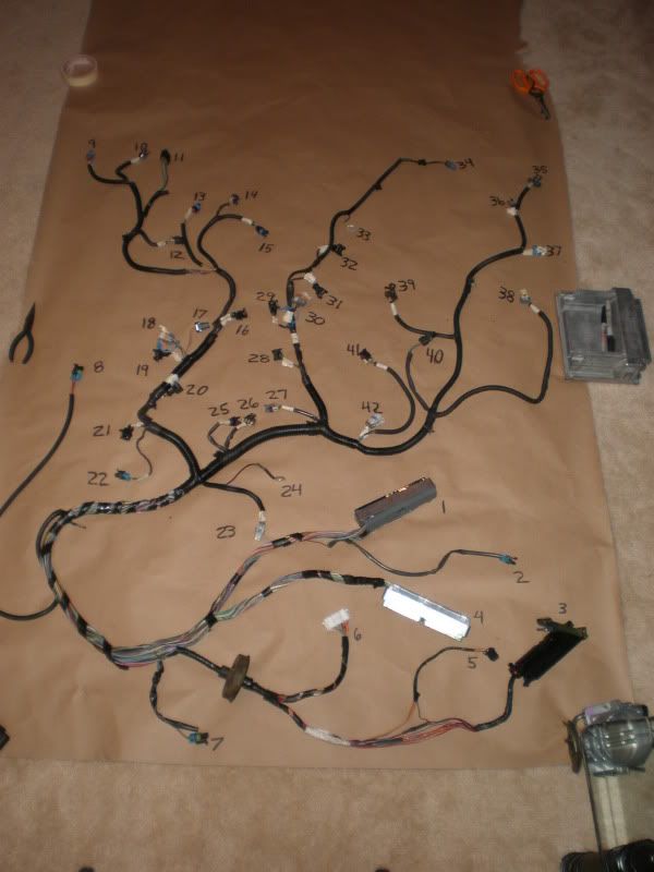
2004 LS1 GTO harness connector identification
I borrowed this idea from Skele4door’s 99-02 harness connector identification thread and found it extremely helpful. I have seen that there are many others that have had trouble finding info on the 04 GTO harness so I decided to follow Chris’ path and make this available for others. So, hopefully others find this beneficial.
I’m going to remove all unnecessary wires in this harness and use this in my turbo LQ4 240sx conversion project.
I spent several hours today working through my harness, 04 GTO PCM pinouts from www.chevythunder.com , Jon D. Rodder’s guide to using a LS1/T56 in a swap, and Skele4door’s thread. I decided to hold off dissecting my entire harness just incase someone else had the same questions I did.
To my knowledge, based on the person I got the PCM and harness from and my own research, this is a 6 speed harness.
Please feel free to make any additions to the unidentified connectors or corrections to the ones I have already identified. Let me know if there are any questions regarding the picture posted. I can take more detailed pics of the unidentified connectors if needed.
Thanks,
Avery
1. PCM blue
2. coolant level sensor
3. ASM (accelerator and servo control module)
4. PCM green
5. PIM (powertrain interface module)
6. C206 body connector
7. driver's side horn
8. throttle relaxer
9. IAT
10. AC pressure
11. a/c clutch, CAGS, injector voltage, neutral switch, ground
12. MAF
13. ECT
14. TPS
15. IAC
16. Injector
17. EVAP solenoid
18. Coil connector
19. Injector
20. Injector
21. Injector
22. Knock sensor
23. Driver’s O2
24. ground
25. Oil pressure
26. Cam sensor
27. MAP
28. Injector
29. Injector
30. Coil connector
31. Injector
32. Injector
33. ground
34. a/c clutch
35. rear O2
36. VSS
37. Reverse lockout
38. CAGS
39. rear O2
40. reverse lamp switch
41. Crank sensor
42. Passenger’s O2
Last edited by 91 240; Sep 27, 2009 at 12:05 PM. Reason: update
2 or 34 is probably AC clutch supply voltage and the other is probably Low Reference - EOP Sensor.
The pic is kinda small and I'm just using process of elim based on the '04 GTO pinouts diagram. The other GN are injectors which you already have.
Frank
The pic is kinda small and I'm just using process of elim based on the '04 GTO pinouts diagram. The other GN are injectors which you already have.
Frank
11 goes to the a/c pressure switch, and abs sensors. Might go to something else too.
2 is the coolant level sensor.
And 7 is the drivers side horn.
34 is for the a/c clutch.
2 is the coolant level sensor.
And 7 is the drivers side horn.
34 is for the a/c clutch.
Last edited by oct03gto; Sep 26, 2009 at 06:53 AM.
Email me a fax number and I'll send you some wiring info rskir@optonline.net[/email] I used the gto 04 harness in my nova.
found a little more info on plug #11
gray/blue - neutral switch
green - a/c compressor clutch supply voltage (goes to PCM green connector #18, and connector #34 above
pink/blue - CAGS
light green - ignition voltage for driver side injectors
red - ignition voltage for passenger side injectors
black/red - ground
gray/blue - neutral switch
green - a/c compressor clutch supply voltage (goes to PCM green connector #18, and connector #34 above
pink/blue - CAGS
light green - ignition voltage for driver side injectors
red - ignition voltage for passenger side injectors
black/red - ground
Trending Topics

Teching In
Joined: Oct 2009
Posts: 5
Likes: 0
I have the entire wiring diagram for a 2004 Pontiac GTO let me know if anyone need a copy it is almost 7MB so I could not upload. Also has any one figured out the C206 connector I am having one hell of a time. I have description but having a hard time figuring it out. e-mail me badmas_manche@yahoo.com if you need a copy.
LS1 Tech Stories
The Best V8 Stories One Small Block at Time

Gas Monkey Built a 6-Wheel Ferrari Testarossa With a Corvette LT4 Engine
Verdad Gallardo
7 Most Reliable High-Performance Engines GM Has Ever Built
Verdad Gallardo
Amazing '71 Camaro Restomod Is Modern Muscle Car Under the Skin
Verdad Gallardo
6 Common C5 Corvette Failures and What's Involved In Repairing Them
Pouria Savadkouei
Retro Modern Bandit Pontiac Trans AM Comes With Burt Reynolds' Autograph
Verdad Gallardo
Top 10 Greatest Cadillac V Series Performance Models Ever, Ranked
Pouria Savadkouei
Top 10 Most Powerful Chevy Trucks Ever Made!

Hennessey's New Supercharged Silverado ZR2 Has 700 HP
Verdad Gallardo
Coachbuilt N2A Anteros Is an LS2-Powered C6 Corvette In Italian Clothes
Verdad Gallardo
Staging Lane
Joined: Oct 2006
Posts: 62
Likes: 0
I have the entire wiring diagram for a 2004 Pontiac GTO let me know if anyone need a copy it is almost 7MB so I could not upload. Also has any one figured out the C206 connector I am having one hell of a time. I have description but having a hard time figuring it out. e-mail me badmas_manche@yahoo.com if you need a copy.
Teching In
Joined: Oct 2009
Posts: 5
Likes: 0
The issue is I would like to know which wires from the C206 are connected to the ignition wires in my RX7. A little more details than just short descriptions. And what do I do with plug #11 in the picture (a/c clutch, CAGS, injector voltage, neutral switch, ground) can I just leave it hanging or do I have to connect it to something
Thank you
Thank you
Teching In
Joined: Oct 2009
Posts: 5
Likes: 0
I have this details but I need more details.
LS1 2004 Pontiac GTO C-206 Body connector Layout
Pin Wire Color Function
1 (WH) EVAP Canister Vent Solenoid Control
2 (BK) Low Reference
3 (PU/WH) VSS Signal
4 (PU) Fuel Level Sensor Signal
5 (BU/WH) High Speed Cooling Fan Relay Control
6 (OG) Battery Positive Voltage
7 (BN/BU) Ignition 1 Voltage
8 (0G) Ignition 3 Voltage
9 (BK/WH) Delivered Torque Signal
10 (GN) Content Theft Horn Control
11 (GY) Neutral Safety Switch Signal
12 (D-GN) Fuel Tank Pressure Sensor Signal
13 (PK) Ignition 1 Voltage
14 (GY) 5-Volt Reference
15 (L-GN/BK) A/C Compressor Clutch Relay Control
16 (PU) Brake Signal
17 (OG/WH) Requested Torque Signal
18 (RD) Ignition 1 Voltage
19 (BN/WH) MIL Control
20 (RD/BK) UART Serial Data Primary
21 (RD/YE) Battery Positive Voltage
22 (L-GN) Backup Lamps Supply Voltage
23 (GN/WH) Fuel Pump Relay Control
24
25 (BN) Engine Speed Signal
26 (YE) RFA Class 2 Serial Data
Staging Lane
Joined: Oct 2006
Posts: 62
Likes: 0
The issue is I would like to know which wires from the C206 are connected to the ignition wires in my RX7. A little more details than just short descriptions. And what do I do with plug #11 in the picture (a/c clutch, CAGS, injector voltage, neutral switch, ground) can I just leave it hanging or do I have to connect it to something
Thank you
Thank you
Hope it helps.
I'm using 2004 gto stuff too. Looks like the bcm controls the low speed fan and pcm controls the high speed. Any one figued out a way to run a low speed. Thing of wiring it to an unused out put such as ac, evap, egr and tune it to activate at certain temp. Any other ideas.
I'm using 2004 gto stuff too. Looks like the bcm controls the low speed fan and pcm controls the high speed. Any one figued out a way to run a low speed. Thing of wiring it to an unused out put such as ac, evap, egr and tune it to activate at certain temp. Any other ideas.
Guys sign up for alldata $25 for one car one year all the info you need is listed .I was able to do 90% of my wiring without it,but got tried on searching the net for info.Best $25 I spent.
Staging Lane
Joined: Oct 2006
Posts: 62
Likes: 0
I'm using 2004 gto stuff too. Looks like the bcm controls the low speed fan and pcm controls the high speed. Any one figued out a way to run a low speed. Thing of wiring it to an unused out put such as ac, evap, egr and tune it to activate at certain temp. Any other ideas.
PS you will need to add a pin in the connector as in the GTO configuration it isn�t used, so no need for the BCM.
Teching In
Joined: Oct 2009
Posts: 5
Likes: 0

Teching In
Joined: Oct 2009
Posts: 20
Likes: 0
Does anyone have any idea how to make one of these stand alone?
I have an ls1 from a 2002 Holden Monaro. These pinouts are very similar to mine http://www.chevythunder.com/2004_gto_pcm_pinouts.htm and the above loom is very similar, but not 100%.
I've been following rodder's guide for making an f-body harness stand alone but the plugs are too different. E.g. "C100 plug, A PNK, Connect to Fuse IGN1 - Hot in Run and Start", no idea where to find this wire.
Any help would be appreciated.
On The Tree
Joined: Aug 2007
Posts: 175
Likes: 0
I am using the 04 GTO harness in mine as well. I had mail order trim the package and some things where left out for me to hook up like traction control on/off option. Can the BCM be eliminated? As well as is there a way to eliminate the traction control out of the system. I have posted comments on HPTuners but to no avail.
