


 I've been looking into custom ***** for a while, Do you think you would make and sell these? I would totally buy them, they are super nice!
Custom Firebird HVAC Knobs
Thread Starter
Copy & Paste Moderator


Joined: Apr 2002
Posts: 9,764
Likes: 208
From: Eastern MA
I've seen some on here modify Aftermarket Metal Mazda 6 ***** to fit. The "D" hole in the shaft is too large and 180* offset from what we need (in other words, the indicator notch would point the exact opposite direction. Each set comes with 2 larger and one smaller **** so I had bought 2 sets of ***** to be able to get 3 larger ones the same size.
So I tried modifying the *****...
- Disassembled the **** (Press out the centers from the rings - by hand)
- Removed the face with heat and prying
- Trimmed raised notch of indicator and glued the face back on 180* offset
- Painted the back with transparent red
- Glued metal shim from stock-style **** in the hole of the Mazda shaft to shrink it down.
I didn't really like the results all that much. It was OK, but didn't light as evenly as I wanted.
So I turned to 3D Prining. I used PETG filament so it should take the heat of being inside a car. For all the measurements and test fittings, I used a spare HVAC panel I bought on ebay.
Also, the larger ***** I thought were slightly too large (overlapping the diagrams on the HVAC Face) and I didn't want to buy another set so I used the two smaller ***** for the left and right positions and used the larger **** for the center position. They are barely different in size so it might not be too obvious in the pictures.
To Prep the *****...
- Disassembled the **** (Press out the centers from the rings - by hand)
- Removed the face
- Trimmed off the raised ring from the clear insert
- Sanded with 60, then 220, then 400, then buffed with Meguiar's PlasticX
(I didn't take pics of the sanding, but I put the **** in a drill via its shaft to speed things up)
(This is to remove the glue residue and leave a smooth and fairly clear surface)
- Cut off shaft
- Design new shaft
- Prototype different faces
- Paint the face (8+ coats of transparent red, 6+ coats of black, 2 coats of Gloss Clear on the red and center only). I used brush on paint to keep it targeted and used thin coats so as not to get runs.
(The red is watery. It was like painting with thin blood. Smells like strange alcoholic candy too.)
- Install the faces in the ring
- Push in the clear insert
- Install the shaft so the flat side of the "D" faces the same way as the point of the emblem on the **** face
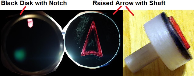
Here is the **** disassembled next to the one that I initially modified to fit:

Here is how the ***** are now assembled:

http://www.fadingarrow.net/images/Fi...20Assembly.jpg
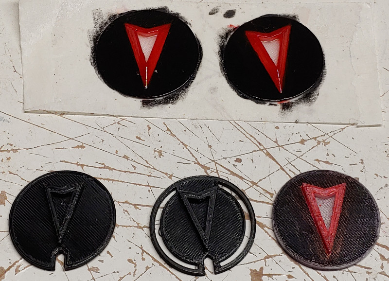
Here are the different prototypes I tried. I tried plain black with a notch or ring to pass light through. I've tried with clear filament (which looks frosted when printed) and a raised arrow and beveled arrow. I also tried a whole face/insert/shaft together, but that one didn't allow as much even lighting through as printing a thin clear disk and using the insert from the original ****. The sloppier painted prototypes below are actually using either markers or quick paint job. I just wanted proof-of-concept and wasn't too worried about being perfect for a prototype.
http://www.fadingarrow.net/images/Fi...Prototypes.jpg
http://www.fadingarrow.net/images/Fi...th%20Notch.jpg
http://www.fadingarrow.net/images/Fi...ith%20Ring.jpg
http://www.fadingarrow.net/images/Fi...th%20Notch.jpg
http://www.fadingarrow.net/images/Fi...ed%20Arrow.jpg
The final version I went with is a thin clear disk with a beveled arrow. I painted the arrow red, left the center clear, and painted around in black.
Here is part way through painting the arrows on the final version of the **** faces. The red paint is Tamiya Transparent Red. I wanted something I could brush on to only paint the arrow red and not the whole disk.
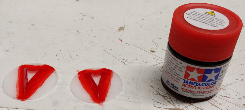
http://www.fadingarrow.net/images/Fi...ed%20Arrow.jpg
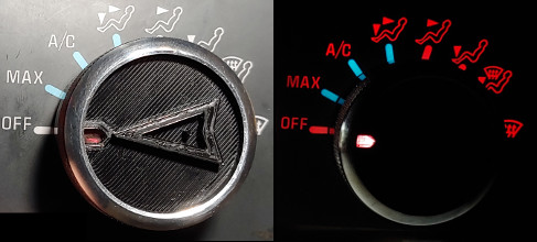
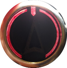
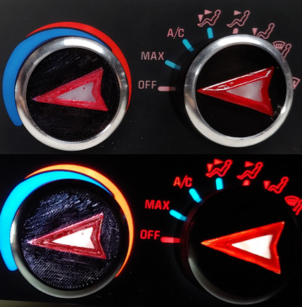
Here is the final version finished
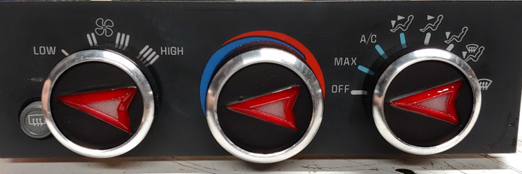
http://www.fadingarrow.net/images/Fi...ed%20Knobs.jpg
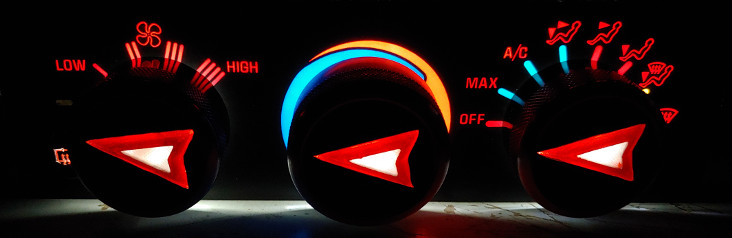
http://www.fadingarrow.net/images/Fi...%20-%20Lit.jpg
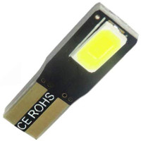
The bulbs were blown in the spare HVAC panel so I replaced them with LEDs. I got the kind with LEDs only on the side since any front ones would face black plastic and would be a waste or possibly make a strange glow spot. Removing the original small glass bulbs was difficult. They wouldn't pull out. I had to break them and pull out the pieces with pliers.
Here are the LEDs I used:
http://www.fadingarrow.net/images/Fi...LED%20Bulb.jpg
Luckily the bulbs are on a separate mini harness so I'll swap that harness to my car when I install the *****.
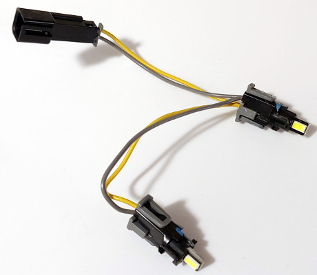
http://www.fadingarrow.net/images/Fi...%20Harness.jpg
So I tried modifying the *****...
- Disassembled the **** (Press out the centers from the rings - by hand)
- Removed the face with heat and prying
- Trimmed raised notch of indicator and glued the face back on 180* offset
- Painted the back with transparent red
- Glued metal shim from stock-style **** in the hole of the Mazda shaft to shrink it down.
I didn't really like the results all that much. It was OK, but didn't light as evenly as I wanted.
So I turned to 3D Prining. I used PETG filament so it should take the heat of being inside a car. For all the measurements and test fittings, I used a spare HVAC panel I bought on ebay.
Also, the larger ***** I thought were slightly too large (overlapping the diagrams on the HVAC Face) and I didn't want to buy another set so I used the two smaller ***** for the left and right positions and used the larger **** for the center position. They are barely different in size so it might not be too obvious in the pictures.
To Prep the *****...
- Disassembled the **** (Press out the centers from the rings - by hand)
- Removed the face
- Trimmed off the raised ring from the clear insert
- Sanded with 60, then 220, then 400, then buffed with Meguiar's PlasticX
(I didn't take pics of the sanding, but I put the **** in a drill via its shaft to speed things up)
(This is to remove the glue residue and leave a smooth and fairly clear surface)
- Cut off shaft
- Design new shaft
- Prototype different faces
- Paint the face (8+ coats of transparent red, 6+ coats of black, 2 coats of Gloss Clear on the red and center only). I used brush on paint to keep it targeted and used thin coats so as not to get runs.
(The red is watery. It was like painting with thin blood. Smells like strange alcoholic candy too.)
- Install the faces in the ring
- Push in the clear insert
- Install the shaft so the flat side of the "D" faces the same way as the point of the emblem on the **** face
Here is the **** disassembled next to the one that I initially modified to fit:
Here is how the ***** are now assembled:
http://www.fadingarrow.net/images/Fi...20Assembly.jpg
Here are the different prototypes I tried. I tried plain black with a notch or ring to pass light through. I've tried with clear filament (which looks frosted when printed) and a raised arrow and beveled arrow. I also tried a whole face/insert/shaft together, but that one didn't allow as much even lighting through as printing a thin clear disk and using the insert from the original ****. The sloppier painted prototypes below are actually using either markers or quick paint job. I just wanted proof-of-concept and wasn't too worried about being perfect for a prototype.
http://www.fadingarrow.net/images/Fi...Prototypes.jpg
http://www.fadingarrow.net/images/Fi...th%20Notch.jpg
http://www.fadingarrow.net/images/Fi...ith%20Ring.jpg
http://www.fadingarrow.net/images/Fi...th%20Notch.jpg
http://www.fadingarrow.net/images/Fi...ed%20Arrow.jpg
The final version I went with is a thin clear disk with a beveled arrow. I painted the arrow red, left the center clear, and painted around in black.
Here is part way through painting the arrows on the final version of the **** faces. The red paint is Tamiya Transparent Red. I wanted something I could brush on to only paint the arrow red and not the whole disk.
http://www.fadingarrow.net/images/Fi...ed%20Arrow.jpg
Here is the final version finished
http://www.fadingarrow.net/images/Fi...ed%20Knobs.jpg
http://www.fadingarrow.net/images/Fi...%20-%20Lit.jpg
The bulbs were blown in the spare HVAC panel so I replaced them with LEDs. I got the kind with LEDs only on the side since any front ones would face black plastic and would be a waste or possibly make a strange glow spot. Removing the original small glass bulbs was difficult. They wouldn't pull out. I had to break them and pull out the pieces with pliers.
Here are the LEDs I used:
http://www.fadingarrow.net/images/Fi...LED%20Bulb.jpg
Luckily the bulbs are on a separate mini harness so I'll swap that harness to my car when I install the *****.
http://www.fadingarrow.net/images/Fi...%20Harness.jpg
Last edited by VIP1; Dec 8, 2020 at 06:32 PM.
Thread Starter
Copy & Paste Moderator
Joined: Apr 2002
Posts: 9,764
Likes: 208
From: Eastern MA
My brother just noticed that some of the words above are being censored. I just saw his screenshot and it appears that the word "****" is being replaced with asterisks. AHAHAHHAAHA. British slang being censored and in this context it isn't something that needs to be censored.
In case it is still censored... the word was K N O B
In case it is still censored... the word was K N O B
Thread Starter
Copy & Paste Moderator
Joined: Apr 2002
Posts: 9,764
Likes: 208
From: Eastern MA
For anyone else interested in this, that translucent red paint eventually bubbled at the edges while installed in the car and I need to re-do this. I don't know if the issue is the paint reacting to the heat and sun inside the car or the plastic off-gassing (but the black paint is fine). Probably need to reprint the **** faces and choose a different paint.
Trending Topics
Thread Starter
Copy & Paste Moderator
Joined: Apr 2002
Posts: 9,764
Likes: 208
From: Eastern MA
I re-did the *****. I had CraftCloud print me a new set of the disks and shafts in translucent clear ABS. The unpainted pieces look the same frosted white appearance as above, but ABS instead of PETG. For the red tint, I already had a spray can of VHT Red Tint from a different project. I sprayed that into a paper bowl and used a brush to apply it. The end result looks just like above but a slightly darker red. Took fewer coats too. I also sprayed a satin clear over the whole disk face afterwards.
LS1 Tech Stories
The Best V8 Stories One Small Block at Time

6 Gifts Neither Your Dad Nor Grad Will Shove Into the 'Trinket Drawer'
Brett Foote
Topdon ONE vs. Artidiag 800 BT2: Which is the Diagnostic Tablet For You?
Pouria Savadkouei
Gas Monkey Built a 6-Wheel Ferrari Testarossa With a Corvette LT4 Engine
Verdad Gallardo
7 Most Reliable High-Performance Engines GM Has Ever Built
Verdad Gallardo
Amazing '71 Camaro Restomod Is Modern Muscle Car Under the Skin
Verdad Gallardo
6 Common C5 Corvette Failures and What's Involved In Repairing Them
Pouria Savadkouei
Retro Modern Bandit Pontiac Trans AM Comes With Burt Reynolds' Autograph
Verdad Gallardo
Top 10 Greatest Cadillac V Series Performance Models Ever, Ranked
Pouria Savadkouei