When you click on links to various merchants on this site and make a purchase, this can result in this site earning a commission. Affiliate programs and affiliations include, but are not limited to, the eBay Partner Network.
The controller processor is an Arduino board. Started off with plans of making a simple controller and then, like the rest of this project, I had a major case of scope creep and kept adding features.
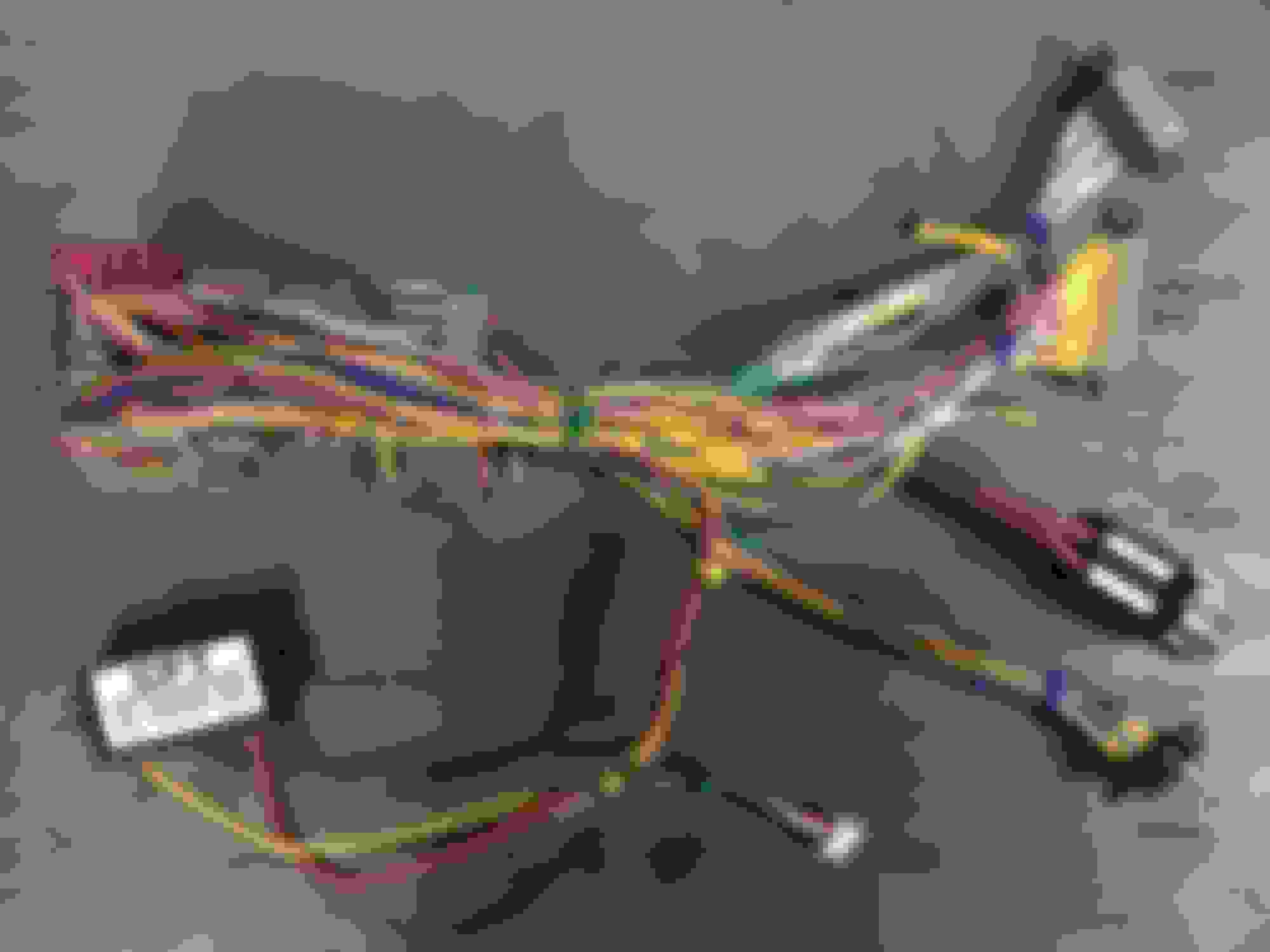
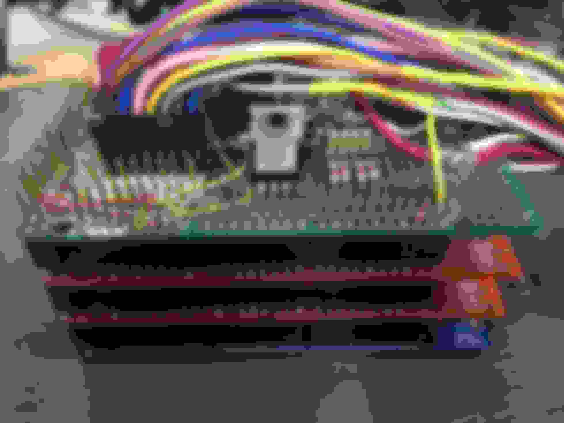
First I added the required set of peripheral components like VR sensor for MPH, drivers for the solenoids, map sensor etc.
Then I added a display panel and some buttons and an Xbox Controller Joystick. The control panel doubles as a dashboard and a way of changing shift, boost and other parameters. Then I added more sensors. The trans controller also serves as a boost controller.
So I went a little crazy and created a bunch of driving modes. Each driving mode has it's own shifting and boost characteristics.
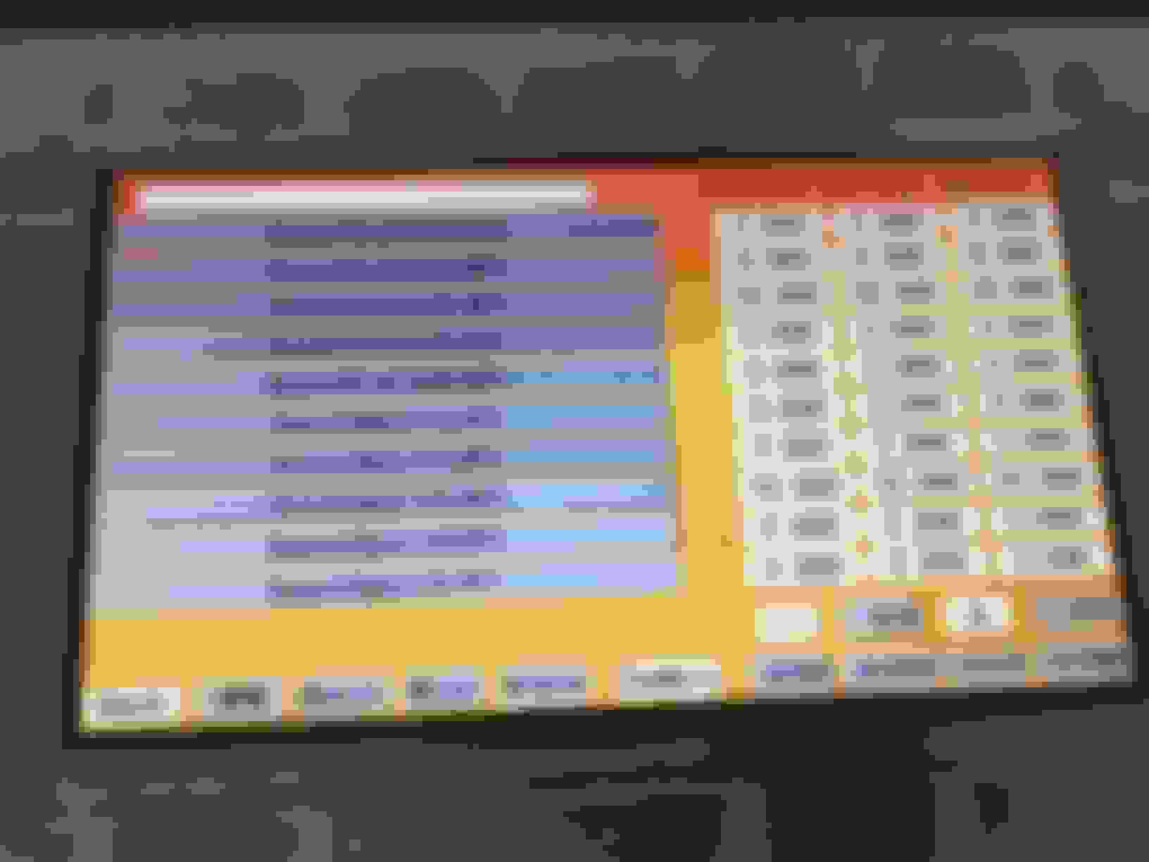
For cruising around, there is Cruise mode. Cruise mode shifts based on MPH and load (vacuum/boost). Cruise mode can use all 4 gears and lockup. Shift tables for each gear/load can be changed from the control panel. Rules are in place to protect against downshifts that will overrev the engine and also shift up a gear in case the engine exceeds the maximum rev limit. Each gear also has a target boost. Line pressure is controlled by load and mode.
Some other modes, Burnout mode. Only shifts based on engine RPM and only goes up to a preset gear. When the burnout is done, the controller automatically changes to Drag mode. Drag mode also shifts by RPM and only shifts up to 3rd gear. No 4th, no lockup. Drag mode also has a target boosts for each gear.
There is also a Dyno mode and a joystick (similar to paddle shift) mode.
The controller also logs maximum/minimum values and alarms.
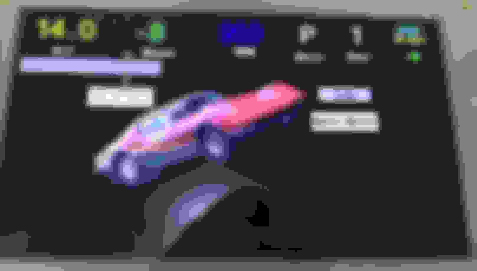
Display shows gear, mph, rpm, oil pressure, fuel pressure, boost/vacuum, boost target for current gear, oil temp and engine temp on the primary display. There is a switch to toggle in 2 additional displays for things like line pressure, trans temp, and max/minimum readings reached.
I built a simulator using another Arduino board to test as much as possible before it goes in the car.
In the video, the controller is in paddle mode, being shifted by the Xbox Joystick.
I have no intentions of making a product of this. It's a hobby and I've ruined some of my other hobbies by turning them into business before.
The controller processor is an Arduino board. Started off with plans of making a simple controller and then, like the rest of this project, I had a major case of scope creep and kept adding features.
First I added the required set of peripheral components like VR sensor for MPH, drivers for the solenoids, map sensor etc.
Then I added a display panel and some buttons and an Xbox Controller Joystick. The control panel doubles as a dashboard and a way of changing shift, boost and other parameters. Then I added more sensors. The trans controller also serves as a boost controller.
So I went a little crazy and created a bunch of driving modes. Each driving mode has it's own shifting and boost characteristics.
For cruising around, there is Cruise mode. Cruise mode shifts based on MPH and load (vacuum/boost). Cruise mode can use all 4 gears and lockup. Shift tables for each gear/load can be changed from the control panel. Rules are in place to protect against downshifts that will overrev the engine and also shift up a gear in case the engine exceeds the maximum rev limit. Each gear also has a target boost. Line pressure is controlled by load and mode.
Some other modes, Burnout mode. Only shifts based on engine RPM and only goes up to a preset gear. When the burnout is done, the controller automatically changes to Drag mode. Drag mode also shifts by RPM and only shifts up to 3rd gear. No 4th, no lockup. Drag mode also has a target boosts for each gear.
There is also a Dyno mode and a joystick (similar to paddle shift) mode.
The controller also logs maximum/minimum values and alarms.
Display shows gear, mph, rpm, oil pressure, fuel pressure, boost/vacuum, boost target for current gear, oil temp and engine temp on the primary display. There is a switch to toggle in 2 additional displays for things like line pressure, trans temp, and max/minimum readings reached.
I built a simulator using another Arduino board to test as much as possible before it goes in the car.
In the video, the controller is in paddle mode, being shifted by the Xbox Joystick.
I have no intentions of making a product of this. It's a hobby and I've ruined some of my other hobbies by turning them into business before.
would it be possible to share your code with us or me I'm going to be running a 4l80 with an arduino behind a cummins first gen and would like to see how you went about it
would it be possible to share your code with us or me I'm going to be running a 4l80 with an arduino behind a cummins first gen and would like to see how you went about it
Great to hear you'll be building your own controller. If you keep it simple it should be pretty easy to do.
I'm not in business and like to share. But in this case it's not possible to share the entire code as it's evolved to more than just a transmission controller.. It controls lots more than the transmission and it's over 13,000 lines of code and growing. It's not road tested yet, but I hope to get it on the road soon.
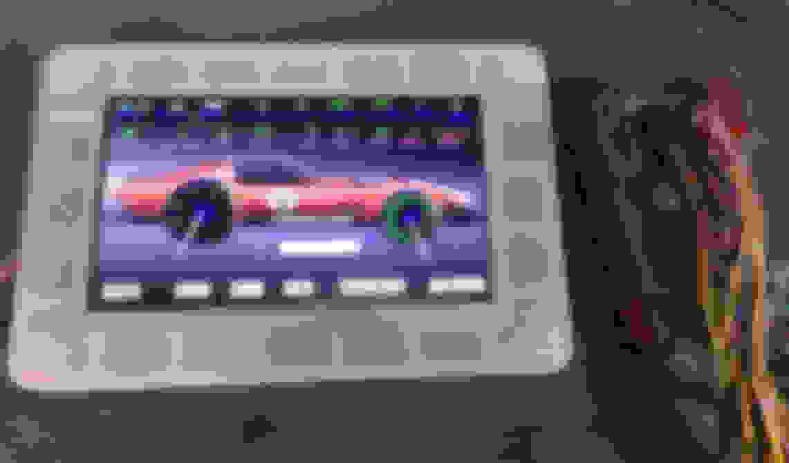
Since that video, I've completely redesigned it. Now it's got a touch screen interface and talks canbus to the engine management, controls boost, PWMs my 8 fans and two fuel pumps.
I'm happy to share parts of the code and discuss any of the electronics. I'd really prefer to do some road testing first.
Also VERY interested in this. I would gladly send you some money via paypal for a "how to" build list with code included.
If you could put together some diagrams and a parts list along with the code I would be very happy to pay you what your time is worth.
Thanks!
Save your money. I'm not in business. I will provide info on the parts I used and I'll provide some of the code I use. There's too much liability if I provide a how to.
For basic operation, here are some parts I've used.
Processor - Arduino Mega. It's cheap, fast enough, lots of ports. I first used the Due, but found that there were power up issues and didn't like the 3.3 volt operation.
Mosfets to drive the solenoids - I've used 4 IRL540. They have logic level gate drives which makes them easy to interface to the arduino and can easily handle any of the solenoid currents without getting hot at all.
Paddle shifting is the easiest shifting method to design, cause your brain is doing all the work to figure out when to shift. However, I would also incorporate RPM information so the controller won't allow dangerous downshifts. In addition, I would incorporate load(MAP or MAF) to control line pressure.
RPM can be gotten from the cam or crank sensor because they are digital signals. Interrupt routines can record when the teeth pass the sensor and other routines can calculate the RPM based on how much time it took for the teeth to pass.
Up shifting by RPM (as in a drag racing car) is the next easiest, but you still need some intelligence to downshift.
Normal automatic shifting needs load, MPH and RPM info as well. MPH info isn't that easy because the transmissions have VR sensors to detect teeth passing by the sensors, instead of hall sensors like the cam and crank, so some additional circuits need to be used to filter the sine VR sensor sine wave to a usable digital signal.
I used to have the transmission controller get RPM, MPH, load (map sensor) info directly from the sensors, but now I get all of that from the engine managements canbus. So in that respect, the new version is a little simpler.
I'm wondering if you would be willing to go into a little more detail on how you are getting a clean RPM signal, and how you have it coded to constantly update.
I've been considering using the #1 coil as a signal, but I see that you mention using the crank/cam signal. Thanks!
Sure. BTW, I now get the RPM from the CANBUS, so it's much simpler. I completely redesigned the whole controller, but I'll post more on that later.
If the coil drive signal is 0-5 volts that would work great. If not, use the cam.
In either case, you would connect the input signal to one of the pins that supports interrupt inputs. Each time that pin changes from high to low, an interrupt routine is triggered that saves the time, in microseconds and adds to the tooth count. Interrupt routines are out of the main loop. Then somewhere in your main loop, you have a routine that checks if the tooth count increase since last time you checked and if so calculate the time difference for the number of teeth that passed to get an RPM. If the time is too long since the last tooth changed, then it's zero RPM. Maybe add some smoothing that averages out the last few readings may help keep it more stable.
I can dig up some of my older RPM code for that and post it here if you're interested.
This is pieceparts of code I pulled from a very old version, of course no guarantees, but it should give you some ideas. It's for a 24 tooth crank sensor. The rpmMult gets changed for different tooth counts.
My old verson of this code had smoothing and making sure that the RPM was stable, reporting on noise, in addition to whatever else was going on in the transmission controller.
Over the past 2 years, I've completely redesigned the DIY 4L80E controller and body module.
The first version was based on an Arduino Due processor board and LCD display. The reason I used the Due was because it was blazing fast. But it had some down sides as well. These down sides included inconsistent power up, 3.3v instead of 5 volt operation and no built in NVRAM (can't store settings when powered off). I worked around these and got it to work, but I wasn't happy with it and the display sucked.
The new (final) version is based on the Arduino Mega board. As it turns out, the Mega is more than plenty fast enough for the task. It's a 5 volt board, so no jumping through hoops to interface it. It can store and retrieve settings after being powered off. Has lots of I/O pins to connect to the rest of the world.
Here is some of the basic functionality:
It controls the 4l80E
PWMs all the fans: 2 radiator, 2 intercooler, trans cooler and oil cooler
PWMs the two fuel pumps
PWMs the alternator
Connects to the AEM infinity with CANBUS
Controls Boost
Controls the BOV
Displays alarms from AEM or itself.
Triggers the AEM two step
Controls the backup lights
Controls the brake lights
Scramble button
Fuel level sensor
Paddle shifting input
Line pressure input
4L80E temperature input
7" touch screen display and control center
I don't plan on having any gauges in the Vette. The touch screen has more than I need to use this car as both a cruiser and strip car.
Also, got rid of that LCD display and replaced it with a 7" touchscreen. This is the display/control with the 6.0 running. This is not the final enclosure, just something I 3D printed.
The Vette can be operated in a bunch of different modes. Each mode has it's own shift logic, shift points, boost in each gear and display screens.
This is cruise mode. Automatic upshifting and downshifting is based on load and MPH or optional paddle shift. Cruise mode and be switched to sport mode which is like cruise mode, but with higher shift points and more boost per gear.
Each mode has many nuances and rules. For example burnout mode can be locked out if the shifter is not in 3. shifting is triggered by RPM only. It only shifts from first to second (optionally 3rd also) and has it's own set of boost levels for each gear. When the MPH comes back down at the end of the burnout, it automatically changes to drag mode.
Upshifts are by RPM and only go to 3rd gear. No lockup. Downshifts are normal.
Two step is automatically turned on at launch time and automatically turned off when the brake pressure is reduced past a set point. I might implement a "Sloppy Brake" when the two step is on.
Drag mode is locked out unless shifter is in 3rd.
Boost targets are different for each gear and two step.
When using the paddle shifters, how much delay (if any) is there between pulling the paddle and the transmission starting to shift? That's always bugged me with the paddle-shifted ATs that I've tried, but I've always wondered if a DIY controller could get the delay down to where the transmission felt more responsive than a manual.
6 Common C5 Corvette Failures and What's Involved In Repairing Them
Slideshow: From wobbling harmonic balancers to failed EBCMs, these are the issues that define long-term C5 ownership and what repairs typically involve.
Retro Modern Bandit Pontiac Trans AM Comes With Burt Reynolds' Autograph
Slideshow: A modern Camaro transformed into a retro icon, this limited-run "Bandit" build blends nostalgia with brute force in a way few revivals manage.
Top 10 Greatest Cadillac V Series Performance Models Ever, Ranked
Slideshow: Cadillac didn't just crash the high-performance luxury vehicle party, it showed up loud, supercharged, and occasionally a little unhinged...
Coachbuilt N2A Anteros Is an LS2-Powered C6 Corvette In Italian Clothes
Slideshow: A one-off sports car that looks like a vintage Italian exotic-but hides a C6 Corvette underneath-just sold for the price of a new mid-engine Corvette.