When you click on links to various merchants on this site and make a purchase, this can result in this site earning a commission. Affiliate programs and affiliations include, but are not limited to, the eBay Partner Network.
Looking forward to thoughts on the MTV up and downshift valves. I have never tried but am told that removing the spring from the MTV up will stop WOT upshift from 1st when in manual low but not sure how that works hydraulically or if even works . I have some other methods but that one would be so easy if indeed true.
__________________ Frank formerly of Performabuilt, Now just me, What can I build for you today? Call or message me. Click sig pic for my facebook
The MTV up and Down are simple in concept but more complex in practice
I've got this about half written up and will be addressing spring in the MTV up and how it can affect the 1-2 "safety shift"
There is some truth to that old wives tale and some...well...not so much truth haha
The MTV up and Down are simple in concept but more complex in practice
I've got this about half written up and will be addressing spring in the MTV up and how it can affect the 1-2 "safety shift"
There is some truth to that old wives tale and some...well...not so much truth haha
Like I said I have studied them and yes they may seem simple but not so much and as I mentioned I have never tried leaving the spring out because honestly I do not see how it can accomplish the end goal and was worried about other unforseen issues and even with the DYNO I used to work with because of its limitations of 1800 rpm I could not really do any solid test in this area and was never motivated enough to do real world test with it in a car.
Look forward to your thoughts on there valves.
__________________ Frank formerly of Performabuilt, Now just me, What can I build for you today? Call or message me. Click sig pic for my facebook
MTV or "Modulated throttle valve" up and downshift valves.
They have a fairly simple function on the surface. But they have a big job and it's somewhat complex.
They are valves placed between the TV and the shift valves.
Their job is to limit/regulate the amount/pressure of TV oil that makes it to the shift valves.
They change the "curve" in which TV oil is delivered to the shift valves.
Let's Look at a simplified shift valve circuit.
On one side of the valve, you have governor oil. Governor oil increases pressure as output shaft speed (and thus road speed) increases.
Governor oil is pushing the valve "out"
On the other end of the valve you have a spring. That spring is pushing the valve "in"
Sortof like a tug of war game.
The shift occurs when the governor "wins" the tug of war and can finally overpower the spring and make the shift valve "snap" to the outboard position. The shift valve can then direct oil to the next clutchpack or band etc.
Seems simple enough. But with just a spring...the shift would always occur at the same speed. No matter what. Heavy throttle, light throttle, wouldn't matter. That would be crappy. Trying to pull a load, or go up a hill, etc and the trans would shift even under heavy load and really bog the engine down.
So, TV oil is used to "help" the spring. TV oil is used in conjunction with the spring to push the shift valve in against governor pressure. This helps to delay the upshifts.
If we just used TV oil direct to the shift valve, the increase in shift speed would be very linear with throttle input.
This is where the MTV up valve comes into play.
The MTV up valve is a regulator valve that is designed to keep any TV oil from getting to the shift valves until 10psi. This is partly due to the fact that for most TV cable setups, at idle there will be some amount of TV pressure in the circuit just due to how the cable is adjusted. So, at idle and very light throttle, the mtv up valve keeps any tv oil from delaying the shift. Making light throttle shifts happen with only the spring pressure. Very predictable and consistent feel for light throttle driving.
After 10psi the valve starts to open and has a "lag" effect to the TV oil.
Tv oil is metered into the MTV up circuit such that MTV up oil is lower than TV pressure until around 55psi. This is best shown with a graph below.
This curve helps progressively delay the shifts rather than perfectly linear delay.
On stock vehicles with stock gearing and stock power...GM felt this was a better experience for the average driver.
In the diagram below (ignore the converter clutch valve) you can see the 2-3 shift valve lineup. The inner valve is being pushed out (to the right) by governor oil.
The spring and MTV up oil is pushing the valve in (left)
Once a shift valve has "snapped" to the upshift position, MTV upshift oil is blocked at the shift valve and will not influence the shift valve any longer. The valve will remain upshifted until you would slow down enough that the spring alone could return the valve to the downshifted position. You can see that in the diagram below. The vale spool blocks the MTV up oil.
This is where MTV down oil comes into play. You can see the shift valve spools allow MTV down oil to route around to end up working with the spring again to push the valve in against governor oil
the MTV down valve works exactly the same as the MTV up...except the MTV down has a stiffer spring and will delay oil into the circuit until around 40psi of TV. Then it will "lag" behind until it catches up at around 60-65 psi as shown in the chart from above.
With the shift valve in an upshifted position, the MTV down oil is allowed to work in conjunction with the spring now.
As you increase throttle, TV pressure increases, and after 40psi MTV down oil will begin to work with the spring.
At a certain amount of throttle vs road speed, the MTV down oil will help the spring win tug of war, and it will push the valve back into the downshift position.
The MTV down valve helps with the timing of these downshifts to match the "feel" of when the downshift should occur.
Once the valve has downshifted, the MTV up oil is allowed to go back to working with the spring, and since MTV up pressure is always the same or higher than MTV down oil...the valve will remain downshifted (until you let off the throttle and governor oil can "win" or until you further increase road speed and the governor oil can "win" and cause another upshift)
I should also mention Detent oil.
Detent oil is introduced after a certain amount of throttle opening. The TV will route extra oil into the detent circuit. The detent oil will work along with the spring and MTV up or down oil to push the valve in against governor oil.
This will help force downshifts with high throttle opening. Specifically intended for passing gear or pulling a hill etc under heavy throttle.
So...in a nutshell that's how the factory used MTV up and MTV down valves to help fine-tune the shift profile.
Now, how might one want to modify these valves to change the behavior of the unit?
Typically, any shift kit won't touch the MTV downshift valve. The factory spring seems to be the right fit for almost all builds and downshift timing works well.
Many shift kits will however mess with the MTV up valve. They will either include a much lighter spring than stock. Or just have you remove the spring completely.
Removing the spring completely will just ensure that MTV up oil follows TV oil without any delay or lag.
This means any shifts under 50% throttle will be slightly delayed vs stock.
In my experience, anything with a higher stall converter, or an engine that makes more power than stock...this is a desirable feel.
What leaving the spring out WON'T do is resist a heavy throttle 1-2 "safety shift" when in manual low. It is common to find that information across different forums from yesteryear...but just examine the oil diagrams for yourself, look at the valve balance and how it works, and you'll find that leaving the spring out won't accomplish the elimination of the safety shift.
Very Cool , As suspected I could not see how removing the spring would prevent the WOT 1-2 shift in manual low 1. As a general rule I leave these two spring and valve alone . But have seen posted many places it would prevent it, As I said I have a few otther ways to accomplish delaying or stopping the shift but sure would have been easy if it did work lol.
__________________ Frank formerly of Performabuilt, Now just me, What can I build for you today? Call or message me. Click sig pic for my facebook
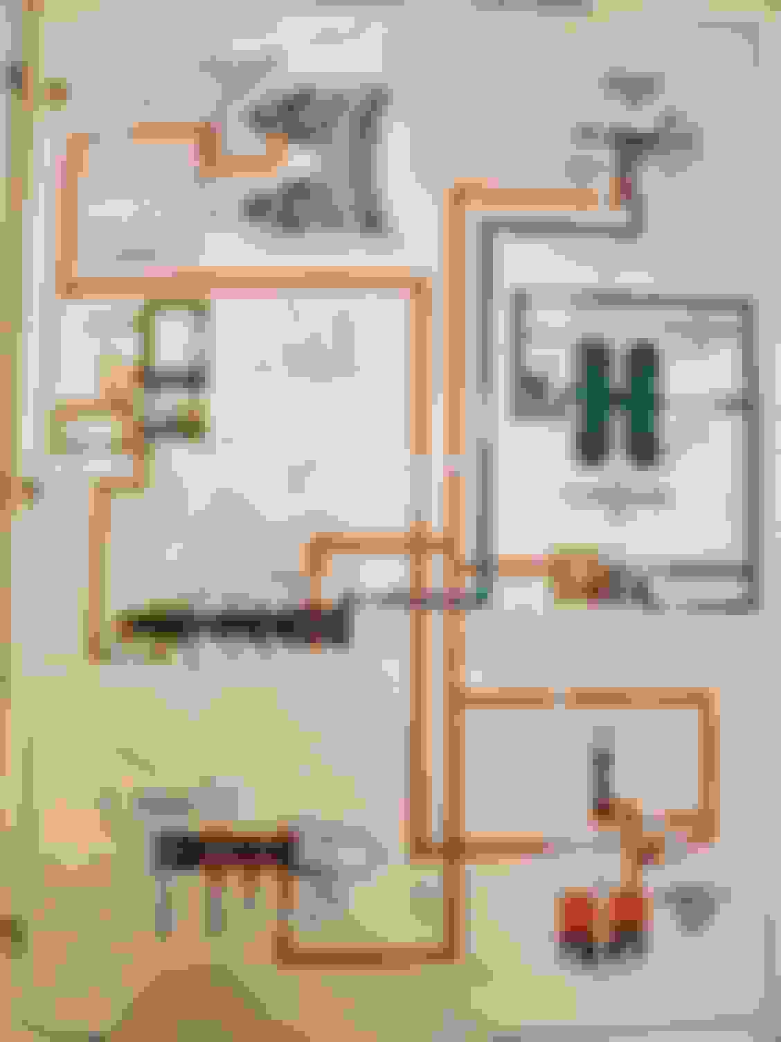
I have a stupid amount of Hydraulic Diagrams from the Multiple Publications/ Volumes of "Principles of Operations" on this Transmission...
as well as the 1987 Aux. Valve-Body Update Guide that was Published.
So I have 4 Different GM Technician's Guides for the THM700-R4 (Pre-Production: 1981, 1st Edition: 1983, Update-Guide: 1987, and 2nd Edition: 1991)...
And wanted to just add some of the Hydraulic Diagrams from them:
Both of the Above Images pertain to the Discussion thus far.
There are also some Nice Diagrams of TransGo Modifications for the 1-2 Safety-Shift, and for the TransGo MTV UP/ DOWN "Manual Valve-Body" Modifications...
That I can also Post here if MaroonMonsta would like to get in to Modifications later on.
I also would just like to say Thank You to MaroonMonsterLS1 for Creating this Thread.
It is like a nice "Time-Capsule" that takes me back in time...
To a Period when Valve-Bodies actually had some very interesting complexities!
With the Current Electronic/ Solenoid Designed Valve-Bodies...
The Functions of various Valve-Trains and the Overall Valve-Body Designs are rather rudimentary (essentially Boring/ No Fun)!
Go ahead and post up the transgo modification diagrams!
Always love having input from others and I hope you and more will join in with some quality posts
I have a stupid amount of Hydraulic Diagrams from the Multiple Publications/ Volumes of "Principles of Operations" on this Transmission...
as well as the 1987 Aux. Valve-Body Update Guide that was Published.
So I have 4 Different GM Technician's Guides for the THM700-R4 (Pre-Production: 1981, 1st Edition: 1983, Update-Guide: 1987, and 2nd Edition: 1991)...
And wanted to just add some of the Hydraulic Diagrams from them:
There are probably more variations to prints than what I have here
But I have the EARLY 1981
Then the Late 81...same cover. Both pre production. But some revisions to the late
1st edition
Update Guide
2nd Edition
Diagnostics and information guide which has some neat breakdowns of hydraulics that the others don't have the same "diagnostic" focused breakdown of
That book is circa 1985
I also have the GM pro-tech manual which is basically useless outside of tq specs and clearances. Intended for the dealer technician doing warranty work.
I have a similar collection of literature for 2004r, th400, th350, 4l60e, 4l80e, etc
I'm always looking for more to add to my collection
My mods to use the 60E pump in the 700R4.
Advantages Easier to get now days, One boost valve, Presure control even in manual first and second, on dyno more linear line rise with throttle. I generally try and use the early 4l60e pumps however have used and tested with later PWM and works same no issues as long as short stator 298mm stator , Been doing this for years and also the added advantage of being able to use a 4L60E deep filter and pan with no adapters extentions.
Disadvantage slightly firmer engagement from park neutral rev to Drive , Not an issue with higher stall converters and can be mediated with smaller forward clutch feed through case.
With .500 boost valve will generally yeild 200 psi at WOT full tv travel in D321 With stiffer Sonnax or transgo PR spring 230 PSl
4L60E PUMP.
BLOCK TUBE FEED IN FORWARD ACCUM WITH CHECK BALL IF PRESENT (older non aux units dont have this of course) (do not go deeper as will block fwd accum feed).
BLOCK D2 FEED IN CASE (Must be done to avoid massive leak in D2 AND D1 MANUAL).
DRILL .93 HOLE AT FWD FEED IN CASE (Hole already there early non aux cases do however suggest orificed .093 cup plug in hole to prevent excessively harsh D4 engagement).
USE 4TH ACCUM SPRING IN ACCUM HOUSING IN PLACE OF STOCK, LEAVE BALL OUT OF ACCUM HOUSING (Failure to do this will result in blocking oil access to fwd clutch accum and very harsh N-D engagement)
This may not be for everyone and that is fine, It does work and I was / am pleased with the results over the years. I do this in my stage 1-2-3 max builds of the 700R4 "4l60" BLOCK THIS HOLE TO AVOID MASSIVE LEAK IN D2 D1 MANUAL BLOCK THIS AS TUBE NO LONGER USED , USE CHECK BALL OR SHORT PLUG DEEPER WILL BLOCK ACCUM FEED DRILL THIS HOLE UNLESS ALREADY PRESENT LIKE IN NON AUX TO .093 IF NON AUX INSTALL CUP PLUG ORIFICED WITH .093 HOLE. FAILURE TO OPEN THIS WILL RESULT IN NO MOVEMENT IN D4 LEAVE THIS BALL OUT ELSE WILL BLOCK FWD ACCUM FEED CAUSE HARSH ENGAGEMENT AND USE 4TH ACCUM SPRING IN PLACE OF STOCK FWD ACCUM SPRING.
__________________ Frank formerly of Performabuilt, Now just me, What can I build for you today? Call or message me. Click sig pic for my facebook
Thanks for sharing Frank. @vorteciroc if you have time to share your notes on the transgo modifications that would be great.
I have similar notes but I like it when multiple people share on a thread and we love having your input
I think I'll write up the 3-2 downshift next
And maybe will cover the accumulators and accum regulator valve also
Yes excellent write up thus far. Always interesting in otther builder tech ideas and ways to do things. It amazes me how each of us many times come up with doing the same things but different methods of getting there.
__________________ Frank formerly of Performabuilt, Now just me, What can I build for you today? Call or message me. Click sig pic for my facebook
Little note on LOCKUP AND TRANS COOLER with the 700R4. With the stock lockup wiring set up it contains a thermal switch which closes at arround 130 to 140f from testing I have done with it. When open lockup is not allowed. With large stand alone coolers and cooler days or climates this may never be acheived or take a very long time to happen. ( Even with my 60E and stand alone cooler during winter many days I never see 130f and if i do and get on highway once in lock up it will generally drop back down well below that with a 4l60e not a biggie but just observation) I Bypass the switch and remove it for this reason. It is the little two prong round one that mounts to VB .
Looking forward to next installment of info here.
__________________ Frank formerly of Performabuilt, Now just me, What can I build for you today? Call or message me. Click sig pic for my facebook
My mods to use the 60E pump in the 700R4.
Advantages Easier to get now days, One boost valve, Presure control even in manual first and second, on dyno more linear line rise with throttle. I generally try and use the early 4l60e pumps however have used and tested with later PWM and works same no issues as long as short stator 298mm stator , Been doing this for years and also the added advantage of being able to use a 4L60E deep filter and pan with no adapters extentions.
Disadvantage slightly firmer engagement from park neutral rev to Drive , Not an issue with higher stall converters and can be mediated with smaller forward clutch feed through case.
With .500 boost valve will generally yeild 200 psi at WOT full tv travel in D321 With stiffer Sonnax or transgo PR spring 230 PSl
4L60E PUMP.
BLOCK TUBE FEED IN FORWARD ACCUM WITH CHECK BALL IF PRESENT (older non aux units dont have this of course) (do not go deeper as will block fwd accum feed).
BLOCK D2 FEED IN CASE (Must be done to avoid massive leak in D2 AND D1 MANUAL).
DRILL .93 HOLE AT FWD FEED IN CASE (Hole already there early non aux cases do however suggest orificed .093 cup plug in hole to prevent excessively harsh D4 engagement).
USE 4TH ACCUM SPRING IN ACCUM HOUSING IN PLACE OF STOCK, LEAVE BALL OUT OF ACCUM HOUSING (Failure to do this will result in blocking oil access to fwd clutch accum and very harsh N-D engagement)
This may not be for everyone and that is fine, It does work and I was / am pleased with the results over the years. I do this in my stage 1-2-3 max builds of the 700R4 "4l60" BLOCK THIS HOLE TO AVOID MASSIVE LEAK IN D2 D1 MANUAL BLOCK THIS AS TUBE NO LONGER USED , USE CHECK BALL OR SHORT PLUG DEEPER WILL BLOCK ACCUM FEED DRILL THIS HOLE UNLESS ALREADY PRESENT LIKE IN NON AUX TO .093 IF NON AUX INSTALL CUP PLUG ORIFICED WITH .093 HOLE. FAILURE TO OPEN THIS WILL RESULT IN NO MOVEMENT IN D4 LEAVE THIS BALL OUT ELSE WILL BLOCK FWD ACCUM FEED CAUSE HARSH ENGAGEMENT AND USE 4TH ACCUM SPRING IN PLACE OF STOCK FWD ACCUM SPRING.
when you do this, are you running a constant pressure setup? I somehow have tied my reverse boost pressure to my tv pressure.
No much like the 4L60E the presure is controlled via the TV cable rather than the PCS in both forward and reverse. You should see rise in rev with TV cable pull. It will not be as high at idle as is typical in rev for the 700r4 but like the 60e will rise with throttle . But yes the presure will vary in reverse just like it does in forward gears with throttle.
__________________ Frank formerly of Performabuilt, Now just me, What can I build for you today? Call or message me. Click sig pic for my facebook
No much like the 4L60E the presure is controlled via the TV cable rather than the PCS in both forward and reverse. You should see rise in rev with TV cable pull. It will not be as high at idle as is typical in rev for the 700r4 but like the 60e will rise with throttle . But yes the presure will vary in reverse just like it does in forward gears with throttle.
well I guess I screwed something up when I tried to duplicate this procedure. I just don�t know what it is.
well I guess I screwed something up when I tried to duplicate this procedure. I just don�t know what it is.
What issue are you having drivability wise? I have been doing this for years with no functional issues. . Line preseure in reverse and forward varies with throttle all operation normal though PRN to Drive a little firmer.
__________________ Frank formerly of Performabuilt, Now just me, What can I build for you today? Call or message me. Click sig pic for my facebook
Gas Monkey Built a 6-Wheel Ferrari Testarossa With a Corvette LT4 Engine
Slideshow: The controversial Ferrari F6 swaps its original flat-12 for a Corvette Z06-derived LT4 V8 and sends power to four rear wheels through a custom-built drivetrain.
7 Most Reliable High-Performance Engines GM Has Ever Built
Slideshow:These GM engines didn't just make huge power, they survived abuse, boost, track days, and six-digit mileage with a reputation for refusing to quit.
6 Common C5 Corvette Failures and What's Involved In Repairing Them
Slideshow: From wobbling harmonic balancers to failed EBCMs, these are the issues that define long-term C5 ownership and what repairs typically involve.
Retro Modern Bandit Pontiac Trans AM Comes With Burt Reynolds' Autograph
Slideshow: A modern Camaro transformed into a retro icon, this limited-run "Bandit" build blends nostalgia with brute force in a way few revivals manage.
Top 10 Greatest Cadillac V Series Performance Models Ever, Ranked
Slideshow: Cadillac didn't just crash the high-performance luxury vehicle party, it showed up loud, supercharged, and occasionally a little unhinged...