
1973 RS Camaro LSX Swap
 09-13-2011, 08:53 PM
#521


 09-13-2011, 10:54 PM
#522


 09-16-2011, 06:09 PM
#523
Well, I’ve still been fiddling around with the car a little bit here and there as I have time. The other day I riveted in my outer window sweeps and installed the door glass, but I didn’t take any pictures of that since it’s just door glass.
Next I moved on to mounting my hood pins. There are some existing empty ˝ inch holes in the core support that I’ve seen some guys use to mount their hood pins through, but they would put the hood pins off center in the body line “valleys” on the hood, and would also place the pin scuff plates at the very front edge of the hood. I don’t care for that look, so I needed to find a way to set the hood pins further back and centered. On most 70-81 F-bodies, there is a short fender brace that runs from the core support to the fender. And since these fender braces dissect the exact area that the hood pins need to be, I’ve seen some guys mount their pins right in the brace bars. But 73 RS Camaros got a much longer, one year only fender brace that has completely different mounting points (further inward on the core support and further back on the fender) that don’t intersect this area. So that left me some open space and the threaded holes on the core support where the standard fender braces would have bolted to work with.
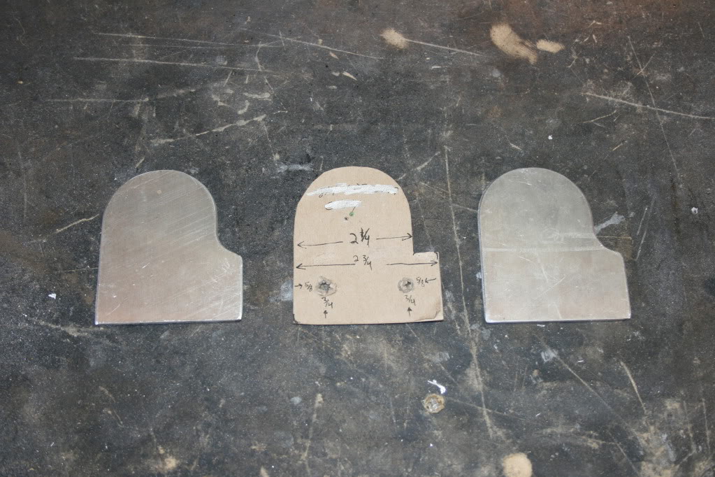
So, I made a pattern out of cardboard for a bracket that I could bolt to the core support and give me an extended platform for the hood pins to bolt through. Once I was happy with the pattern, I took it to a local guy I know that has a CNC plasma table and had them cut them out of .090 aluminum for me.
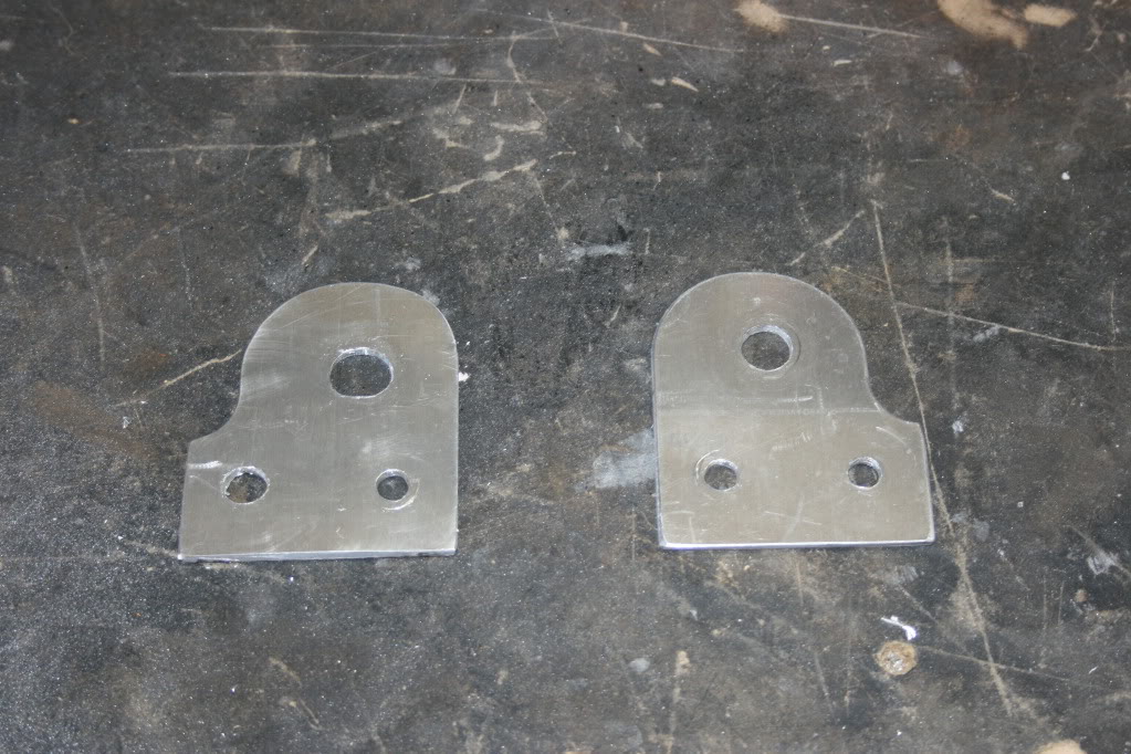
Next I drilled the required holes, and test fit them with the pins installed. One thing I did wrong was make the assumption that the holes I was using had the same spacing on the passenger side as on the drivers side where I took my pattern measurements. Unfortunately, this wasn’t the case, so I had to egg shape the holes on the passenger side bracket. It turns out to be no big deal because the bolt heads cover up the entire hole when installed.
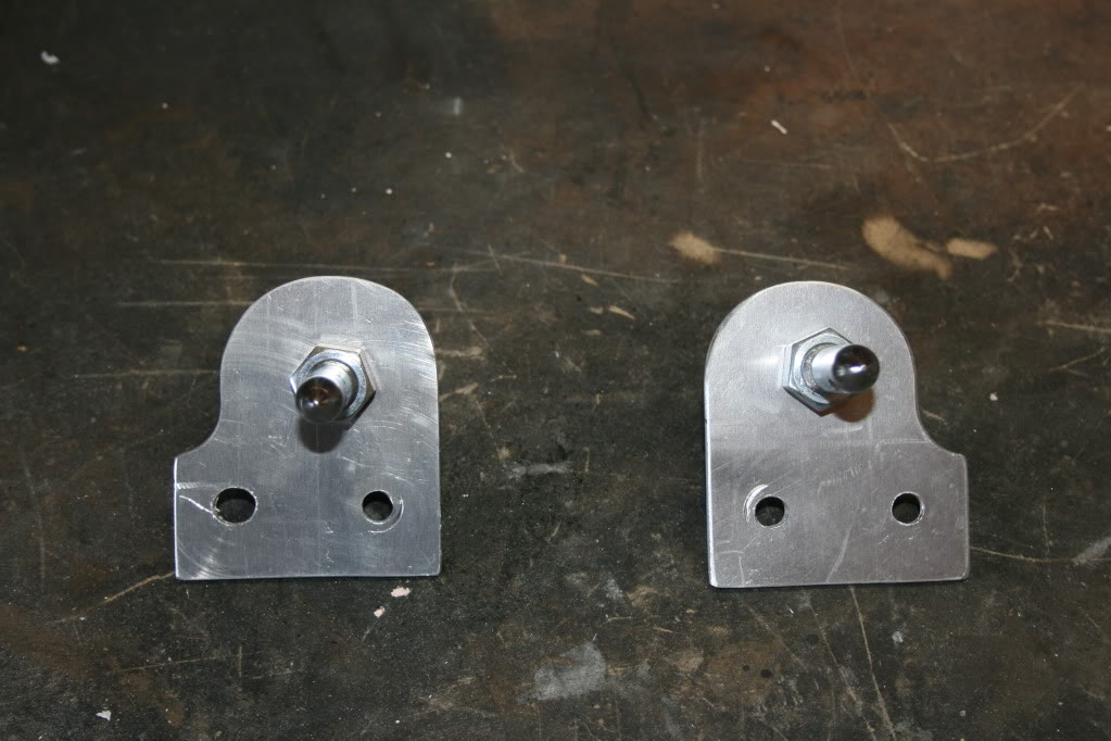
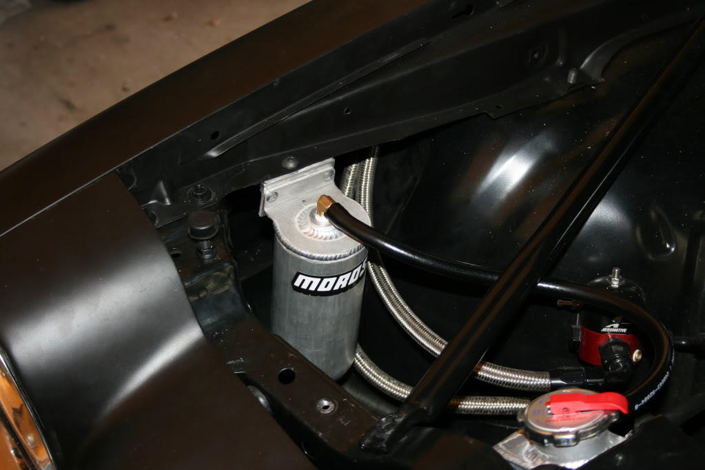
This shot shows the two holes I’m bolting my plates into. The inner hole already has a 5/16 nut welded on the under side from the factory. The unthreaded ˝ inch hole will require a nut and washer on the underside of its bolt, and will also give me a little adjustability. This is actually the spot where I originally had my radiator overflow tank mounted, so you can see in this pic that I’ve relocated it to the fender.
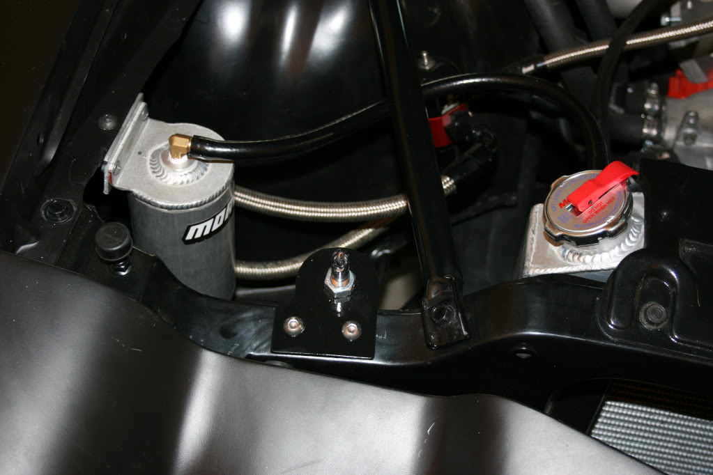
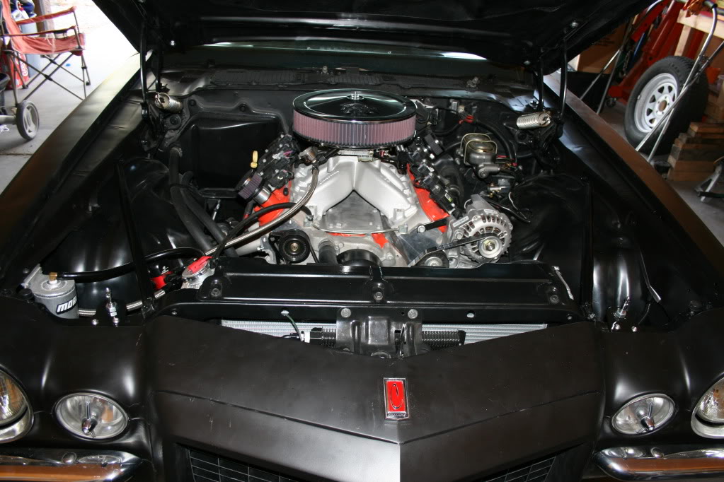
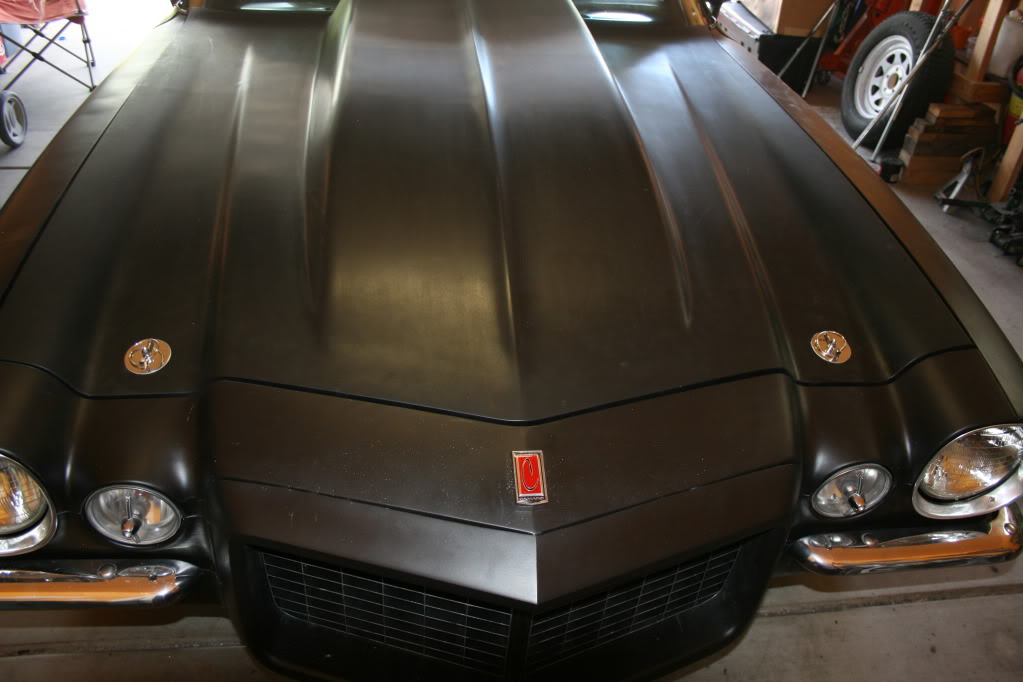
Here’s a few shots with the brackets and pins installed after some paint.

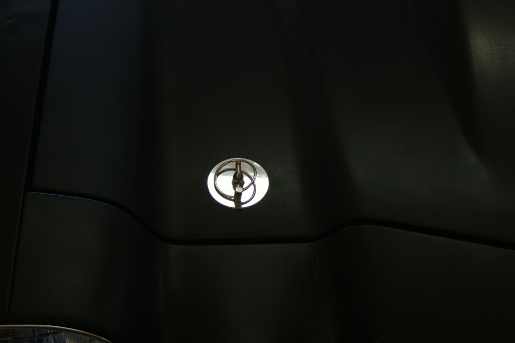
And here it is with the hood closed.
Next I moved on to mounting my hood pins. There are some existing empty ˝ inch holes in the core support that I’ve seen some guys use to mount their hood pins through, but they would put the hood pins off center in the body line “valleys” on the hood, and would also place the pin scuff plates at the very front edge of the hood. I don’t care for that look, so I needed to find a way to set the hood pins further back and centered. On most 70-81 F-bodies, there is a short fender brace that runs from the core support to the fender. And since these fender braces dissect the exact area that the hood pins need to be, I’ve seen some guys mount their pins right in the brace bars. But 73 RS Camaros got a much longer, one year only fender brace that has completely different mounting points (further inward on the core support and further back on the fender) that don’t intersect this area. So that left me some open space and the threaded holes on the core support where the standard fender braces would have bolted to work with.
So, I made a pattern out of cardboard for a bracket that I could bolt to the core support and give me an extended platform for the hood pins to bolt through. Once I was happy with the pattern, I took it to a local guy I know that has a CNC plasma table and had them cut them out of .090 aluminum for me.
Next I drilled the required holes, and test fit them with the pins installed. One thing I did wrong was make the assumption that the holes I was using had the same spacing on the passenger side as on the drivers side where I took my pattern measurements. Unfortunately, this wasn’t the case, so I had to egg shape the holes on the passenger side bracket. It turns out to be no big deal because the bolt heads cover up the entire hole when installed.
This shot shows the two holes I’m bolting my plates into. The inner hole already has a 5/16 nut welded on the under side from the factory. The unthreaded ˝ inch hole will require a nut and washer on the underside of its bolt, and will also give me a little adjustability. This is actually the spot where I originally had my radiator overflow tank mounted, so you can see in this pic that I’ve relocated it to the fender.
Here’s a few shots with the brackets and pins installed after some paint.
And here it is with the hood closed.
 09-16-2011, 08:24 PM
#527

Great job on the brackets and hood pins! Way to think ahead and get everything centered and proffesional looking! Your there man your there!!! I know you have to be chomping at the bit to take it to the track. I know I would! Awesome job on everything.
09-16-2011, 10:47 PM
#528
I'm definately anxious to get it to the track, but I'll have to (or at least I should) wait until at least October to be able to do a few of the more strenuous jobs that need done before the first trip to the track.
I still haven't made up my mind if I should swap the cam before my first track outing or if I should do a before and after cam comparison with two different trips. Before and after would be cool, but I'd really like to sell my current cam to fund a few other things before my first visit to the track, so I guess I'll have to see how that plays out.
One of the main things I still need to do is take the car back to the chassis shop to have the harness tabs relocated further inboard and that means a 6hr round trip on the trailer. So I pretty much refuse to do that before I can afford to also have the chassis NHRA certified while I'm up there. Killing two birds with one stone will make me feel better about making the trip with the car again, and my chassis guy has an NHRA chassis cert tech that will come out to his shop for the regular NHRA cert fee of $150 plus $30 for the "house call".
In reality, the car is nowhere near fast enough to need the chassis cert'd, but since I'm moving from AZ next year, I want to have it cert'd while I'm still here. My chassis guy guarenteed it to certify to 8.50 (just the chassis), but his guarentee isn't worth much to me if I'm on the east coast if it fails to pass. So getting it done right in his shop is a big plus. Also, having it certified should increase the value of the car if, God forbid, I ever have to sell the car. Of course I'll have to keep the certification updated, but I think the first one is probably the biggest hurdle.
09-17-2011, 01:34 AM
#529
Staging Lane
iTrader: (7)
Join Date: Apr 2010
Location: Jefferson City, MO
Posts: 62
Likes: 0
Received 0 Likes
on
0 Posts

3 and 1/2 hours later.... my eyes hurt but I couldnt stop reading your build thread!!! The car looks amazing compaired to what you started with! Im really wanting to get started with more work on my 70 but without the space or money to do it Ill have to keep dreaming and reading great build threads like yours!
Keep up the good work, I look forward to seeing more updates!
Keep up the good work, I look forward to seeing more updates!
09-17-2011, 11:51 PM
#530
3 and 1/2 hours later.... my eyes hurt but I couldnt stop reading your build thread!!! The car looks amazing compaired to what you started with! Im really wanting to get started with more work on my 70 but without the space or money to do it Ill have to keep dreaming and reading great build threads like yours!
Keep up the good work, I look forward to seeing more updates!
Keep up the good work, I look forward to seeing more updates!
I got a little more done today so I should have some more updates soon!
09-19-2011, 07:44 PM
#531
So, I’ve been scratching things off of my list here and there over the past couple of days. This isn’t necessarily in the order things happened, but here’s what I’ve gotten done, along with some pics.
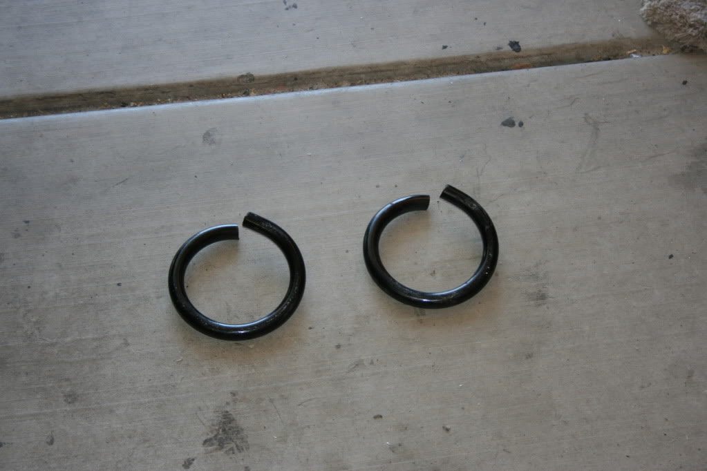
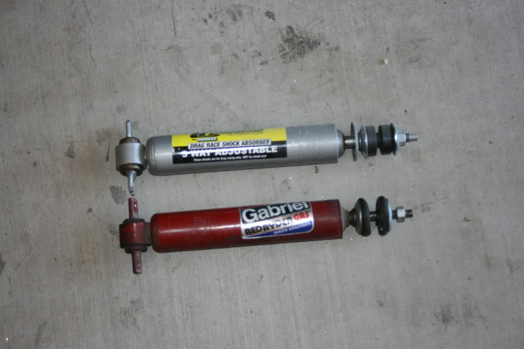
First I’ve cut one coil from each of my Moroso Trick Springs, which gave me about a 2 1/8 inch drop. It could maybe stand to be a touch lower, but I’m not going any lower until I swap out my LH8 pan for an F-body pan for ground clearance reasons. It’s great now because I have 4.5 inches of upward travel and still could remove the upper bump stops if I needed more. While I was at it, I also installed my new CE adjustable front shocks, loosened up and double nutted my lower control arms, and bled my front brakes.
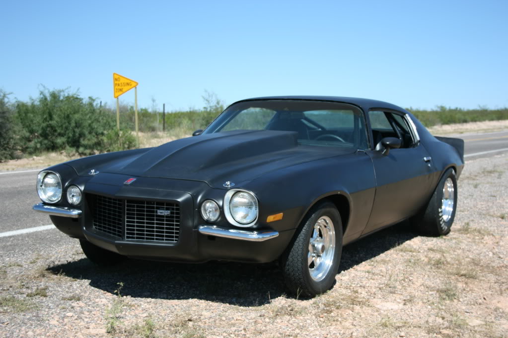
When I was done with all of that, I installed my Caltrac bars and went out to make a few hits. Man does this thing hook up nice on the street!
Here’s the cut coils.
Out with the old Red Riders and in with the CE’s.
And here’s my new ride height.


First I’ve cut one coil from each of my Moroso Trick Springs, which gave me about a 2 1/8 inch drop. It could maybe stand to be a touch lower, but I’m not going any lower until I swap out my LH8 pan for an F-body pan for ground clearance reasons. It’s great now because I have 4.5 inches of upward travel and still could remove the upper bump stops if I needed more. While I was at it, I also installed my new CE adjustable front shocks, loosened up and double nutted my lower control arms, and bled my front brakes.
When I was done with all of that, I installed my Caltrac bars and went out to make a few hits. Man does this thing hook up nice on the street!
Here’s the cut coils.
Out with the old Red Riders and in with the CE’s.
And here’s my new ride height.
09-19-2011, 07:44 PM
#532
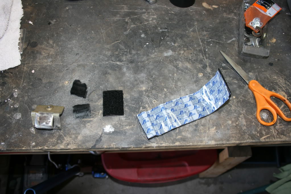
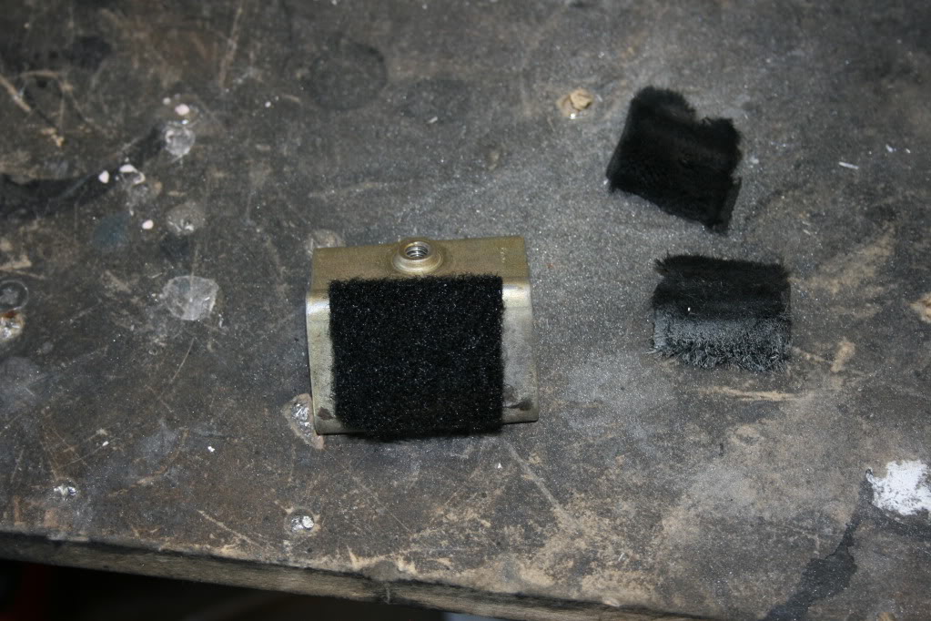
The other day I also installed my roof rail/window weather stripping and adjusted the door glass to fit in the window hole properly. In the process of this, I replaced the worn out old felt on my window guides. To do this, I simply raided my wife’s craft supplies for some self adhesive Velcro. I just used the fuzzy side as a replacement felt. It worked very well and the windows don’t howl anymore when they go up and down.
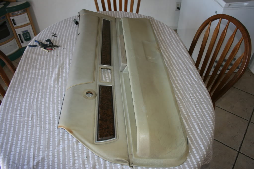
I have also gotten back to working on some interior stuff. Saturday morning I brought my door panels in the house and started disassembling them so they can be cleaned, dyed black, and have new inner window sweeps attached. The old sweeps were as hard as rocks and extremely brittle. It’s hard to believe they were actually rubber at one time. It’s no wonder my side glass is scratched up after being scraped by those things. Here’s some pics of one of the door panels in various states of disassembly.


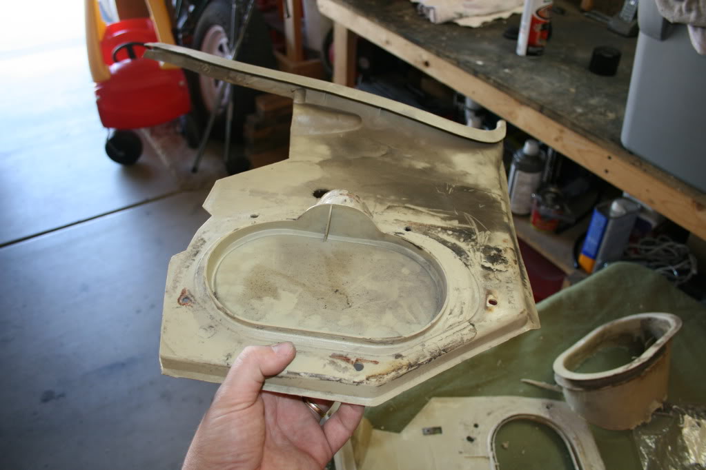
And finally I started to modify my kick panels so that they can be installed with the cage in place. This meant having to chop the floor vent portion off of the passenger side one and just a little trimming on the back of the driver’s side panel since it’s blocked off on an AC car anyways. Both sides will have the vent holes in the car itself blocked off with sheet metal before the panels are reinstalled.

There’s lots of parts cleaning and dying in my future.
I have also gotten back to working on some interior stuff. Saturday morning I brought my door panels in the house and started disassembling them so they can be cleaned, dyed black, and have new inner window sweeps attached. The old sweeps were as hard as rocks and extremely brittle. It’s hard to believe they were actually rubber at one time. It’s no wonder my side glass is scratched up after being scraped by those things. Here’s some pics of one of the door panels in various states of disassembly.
And finally I started to modify my kick panels so that they can be installed with the cage in place. This meant having to chop the floor vent portion off of the passenger side one and just a little trimming on the back of the driver’s side panel since it’s blocked off on an AC car anyways. Both sides will have the vent holes in the car itself blocked off with sheet metal before the panels are reinstalled.
There’s lots of parts cleaning and dying in my future.
09-20-2011, 04:35 PM
#533
Bad back or not you are getting alot done!
Car stance looks so much better!
The beloved interior work, man I spent hours on mine and most of it was on my headliner. I did recover the back seat in the living room everything else was done away from civilization. Looking great keep us posted.
Car stance looks so much better!
The beloved interior work, man I spent hours on mine and most of it was on my headliner. I did recover the back seat in the living room everything else was done away from civilization. Looking great keep us posted.
09-20-2011, 06:24 PM
#534
Thanks man! Now its my "good" back that's my problem. Everything feels so great that I can't help but tackle some of these jobs. I just have to be real careful how I move when I'm on the floor and be sure to use only my arms when loosening or tightening bolts and such. Pulling on non-mobile objects from a poor body position is what got me into this mess in the first place.
I'm not a big fan of the interior work either, but its rewarding when its finished I guess. I was gonna work on my door panels today, but took the car for an alignment instead. Everything feels pretty good now but won't know for sure until I can open her up good at a track.
I'm not a big fan of the interior work either, but its rewarding when its finished I guess. I was gonna work on my door panels today, but took the car for an alignment instead. Everything feels pretty good now but won't know for sure until I can open her up good at a track.
09-23-2011, 03:46 PM
#535
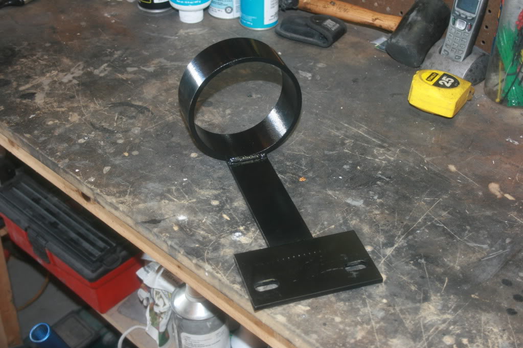
I’m getting a little bit closer to the car being race ready each day. But the next test and tune session at my local track isn’t until October 22nd  . Yesterday I modified and installed my Pro-Touring F-Body (PTFB) driveshaft loop. I really liked this overall design idea of this thing because it’s designed to bolt into an existing location rather than bolting through the floor or welding to the frame or subframe connectors. There were a few mino things that I personally didn’t like for my application, but they were fixable with a little bit of modification.
So by design, this loop was meant to be sandwiched between the top of the transmission mount and the transmission itself. But doing this essentially shims the rear of the transmission up by an amount equivalent to the thickness of the mount plate (a touch over 1/4in with powder coat), and just wouldn’t work for my application. Plus, when I tried installing it in it's intended location, the loop hit the trans tunnel and would need to be bent downward to fit properly. Not a big deal...just a minor issue.
But I decided if I were going to have to bend it (and crack the powder coat) anyway, I may as well modify it completely to fix the trans shim issue as well. I personally thought it would be better suited bolted under the trans crossmember where it wouldn’t interfere with the transmission’s positioning, so I modified it to do just that.
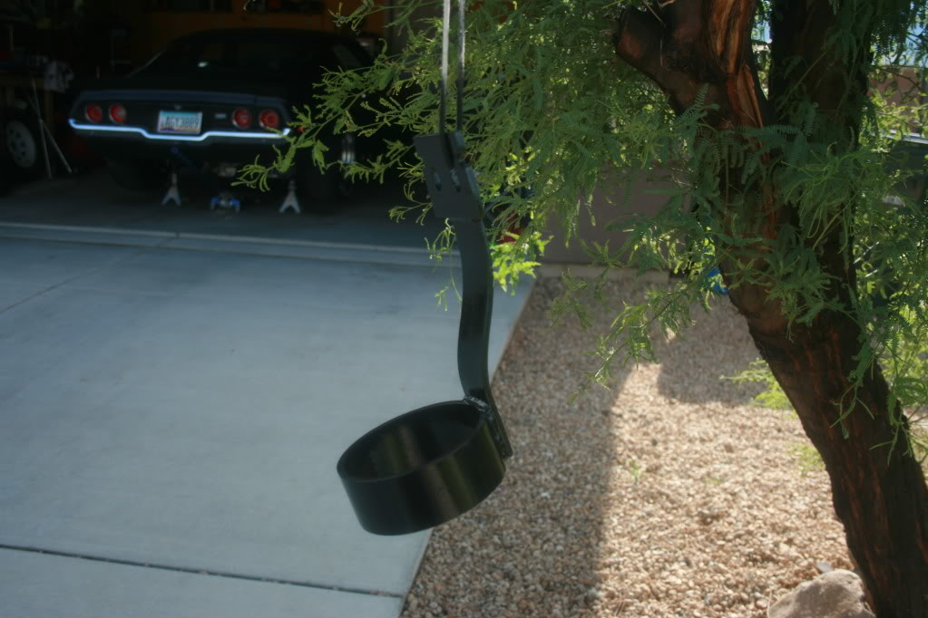
Here is what I started with. The design is a pretty cool idea. But notice the wide bolt pattern that matches the bottom of the trans/top of the trans mount. This is the 1/4 inch piece that would be sandwiched between them.
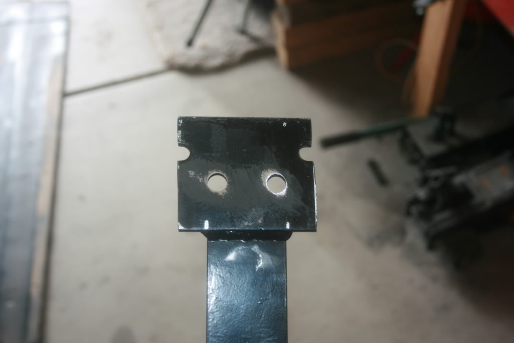
The first modification I made was to trim the sides of the mounting tab so that it would fit on the bottom side of the trans crossmember mounting pad. I also drilled the mounting bolt holes 1 ˝ on center to match the bolt pattern of the crossmember. I later oblonged these holes to give myself some front to rear adjustability.
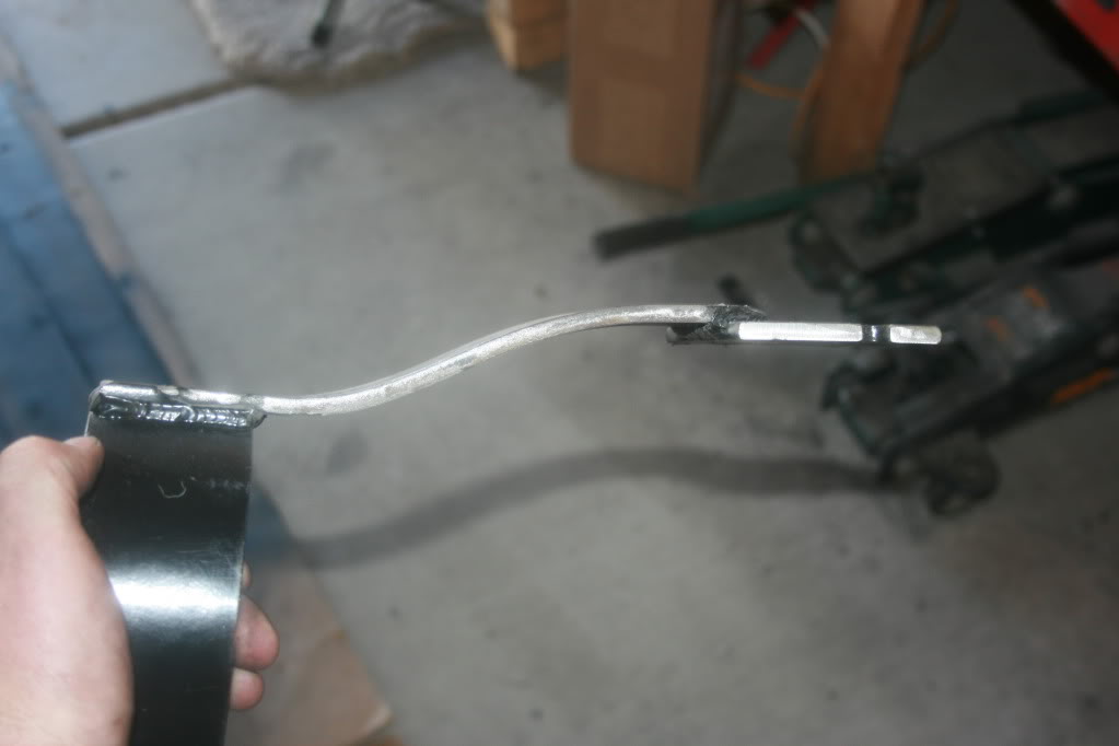
Next, since I had lowered the loop’s mounting point a few inches from its originally intended location, I needed to put an upward dogleg bend in the extension piece to bring the hoop back to the proper height in the tunnel and to provide plenty of clearance above my x-pipe. This was pretty easily done with some heat, a vice and some persuasion, but I lost pretty much all of the powder coat on everything but the hoop itself.
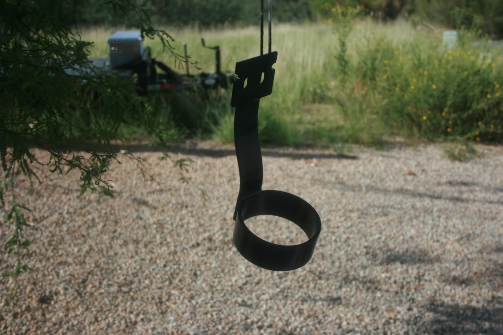
Then I scuffed the remaining powder coat with some sand paper and hit it with some paint.
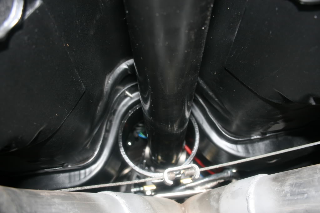
Here are some shots of it bolted in the car. This wasn’t the easiest thing to photograph, so you have to use your imagination a little bit. The first shot shows the loop’s clearance over my x-pipe.
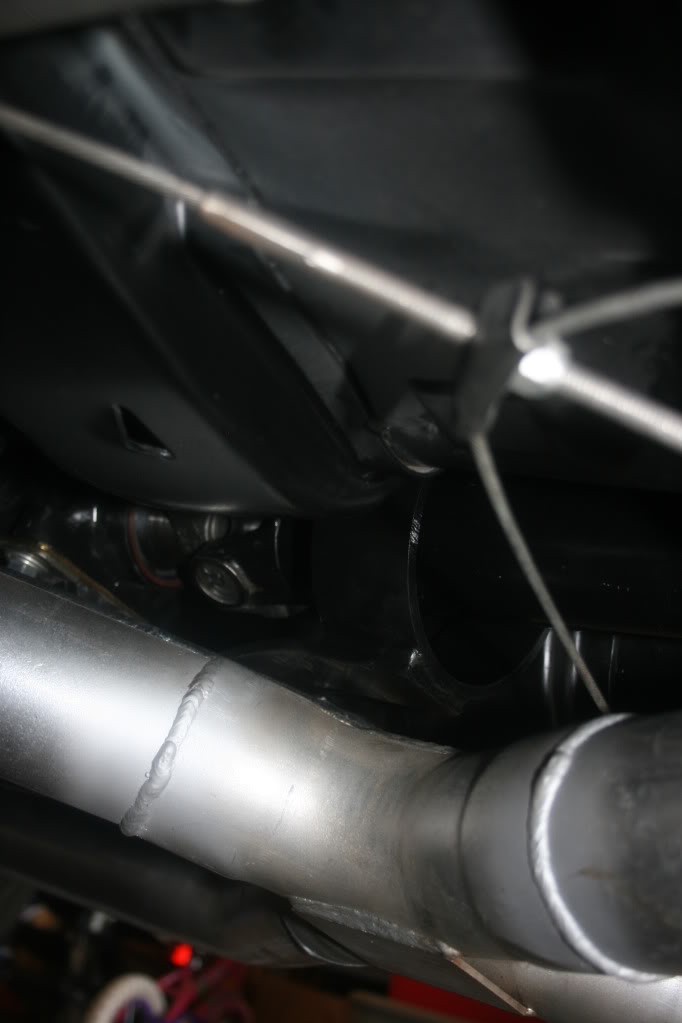
And this shot is taken from the rear looking forward.
I know I also took a pic of where it bolts to the underside of the trans crossmember, but I must have accidentally deleted it.
. Yesterday I modified and installed my Pro-Touring F-Body (PTFB) driveshaft loop. I really liked this overall design idea of this thing because it’s designed to bolt into an existing location rather than bolting through the floor or welding to the frame or subframe connectors. There were a few mino things that I personally didn’t like for my application, but they were fixable with a little bit of modification. So by design, this loop was meant to be sandwiched between the top of the transmission mount and the transmission itself. But doing this essentially shims the rear of the transmission up by an amount equivalent to the thickness of the mount plate (a touch over 1/4in with powder coat), and just wouldn’t work for my application. Plus, when I tried installing it in it's intended location, the loop hit the trans tunnel and would need to be bent downward to fit properly. Not a big deal...just a minor issue.
But I decided if I were going to have to bend it (and crack the powder coat) anyway, I may as well modify it completely to fix the trans shim issue as well. I personally thought it would be better suited bolted under the trans crossmember where it wouldn’t interfere with the transmission’s positioning, so I modified it to do just that.
Here is what I started with. The design is a pretty cool idea. But notice the wide bolt pattern that matches the bottom of the trans/top of the trans mount. This is the 1/4 inch piece that would be sandwiched between them.
The first modification I made was to trim the sides of the mounting tab so that it would fit on the bottom side of the trans crossmember mounting pad. I also drilled the mounting bolt holes 1 ˝ on center to match the bolt pattern of the crossmember. I later oblonged these holes to give myself some front to rear adjustability.
Next, since I had lowered the loop’s mounting point a few inches from its originally intended location, I needed to put an upward dogleg bend in the extension piece to bring the hoop back to the proper height in the tunnel and to provide plenty of clearance above my x-pipe. This was pretty easily done with some heat, a vice and some persuasion, but I lost pretty much all of the powder coat on everything but the hoop itself.
Then I scuffed the remaining powder coat with some sand paper and hit it with some paint.
Here are some shots of it bolted in the car. This wasn’t the easiest thing to photograph, so you have to use your imagination a little bit. The first shot shows the loop’s clearance over my x-pipe.
And this shot is taken from the rear looking forward.
I know I also took a pic of where it bolts to the underside of the trans crossmember, but I must have accidentally deleted it.
09-24-2011, 04:44 PM
#537

As always........ looks GREAT Gary. What gears did you end up going with?
thanks,,
Jim
thanks,,
Jim
10-06-2011, 04:14 PM
#539
Staging Lane
iTrader: (7)
Join Date: Apr 2010
Location: Jefferson City, MO
Posts: 62
Likes: 0
Received 0 Likes
on
0 Posts
The interior will be interesting to see how it turns out. It sucks that your local track doesnt have a test n tune session sooner. I think there are a few people including myself that would like to see how she runs! Keep us posted!